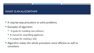
WHAT IS ANALGORITHM?
A step-by-step procedure to solve problems.
Examples of algorithm:
A guide for installing new software
A manual for assembling appliances
A recipes for cooking a dish
Algorithm makes the whole procedure more efficient as well as
consistent.
4.
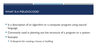
WHAT IS APSEUDOCODE?
Is a description of an algorithm or a computer program using natural
language.
Commonly used in planning out the structure of a program or a system.
Example:
A blueprint for creating a house or building
5.
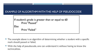
EXAMPLE OF ALGORITHMWITHTHEHELP OF PSEUDOCODE
The example above is an algorithm of determining whether a student with a specific
mark should passed or failed.
With the help of pseudocode, one can understand it without having to know the
technicalities.
If student’s grade is greater than or equal to 60
Print “Passed”
Else
Print “Failed”
6.
WHAT IS AFLOWCHART?
A graphical representation of algorithm.
Like pseudocodes, it is also a description of an algorithm or a computer
program.
Serve as the program’s blueprint during the Program Development
Process.
7.
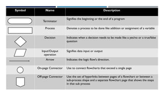
Symbol Name Description
Terminator
Signifiesthe beginning or the end of a program
Process Denotes a process to be done like addition or assignment of a variable
Decision Indicates when a decision needs to be made like a yes/no or a true/false
question
Input/Output
operation
Signifies data input or output
Arrow Indicates the logic flow’s direction.
On-page Connector Use to connect flowcharts that exceed a single page
Off-page Connector Use the set of hyperlinks between pages of a flowchart or between a
sub-process shape and a separate flowchart page that shows the steps
in that sub process
8.
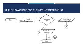
SIMPLE FLOWCHART FORCLASSIFYINGTEMPERATURE
Start
Read
Temperature
Temperature
<=0
Print “Above
Freezing”
Print “Below
Freezing”
End
A
A
9.
WHAT ISTHE RELATIONSHIPOF FLOWCHARTS AND
PSEUDOCODES IN PLANNING?
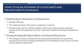
Identifying System Specification and Requirements
Substage of Planning
The needed description of the system or application is acquired.
Purposes, system and user interfaces, database requirements, quality standards, operations,
overview of the whole application, and other requirements needed for the project development is
defined.
Creating the Applicable Diagram Based on the Acquired Requirement
This substage is all about creating flowcharts and pseudocodes based on the requirements
acquired from the previous substage specifically from the identifying the system and user interface
as well as database requirements.
10.
WHAT ISTHE RELATIONSHIPOF FLOWCHARTS AND
PSEUDOCODES IN PLANNING?
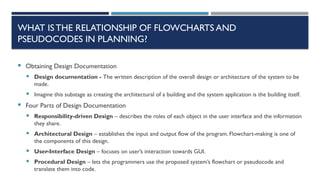
Obtaining Design Documentation
Design documentation - The written description of the overall design or architecture of the system to be
made.
Imagine this substage as creating the architectural of a building and the system application is the building itself.
Four Parts of Design Documentation
Responsibility-driven Design – describes the roles of each object in the user interface and the information
they share.
Architectural Design – establishes the input and output flow of the program. Flowchart-making is one of
the components of this design.
User-Interface Design – focuses on user’s interaction towards GUI.
Procedural Design – lets the programmers use the proposed system’s flowchart or pseudocode and
translate them into code.
11.
WHAT ISTHE RELATIONSHIPOF FLOWCHARTS AND
PSEUDOCODES IN PLANNING?
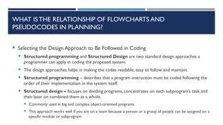
Selecting the Design Approach to Be Followed in Coding
Structured programming and Structured Design are two standard design approaches a
programmer can apply in coding the proposed system.
The design approaches helps in making the codes readable, easy to follow and maintain.
Structured programming – describes that a program instruction must be coded following the
order of their implementation in the system itself.
Structured design – focuses on dividing programs, concentrates on each subprogram’s task and
then later on combined them as a whole.
Commonly used in big and complex object-oriented programs.
This approach works well if you are on a team because a person or a group of people can be assigned on a
specific module or subprogram
12.
WHAT ISTHE RELATIONSHIPOF FLOWCHARTS AND
PSEUDOCODES IN PLANNING?
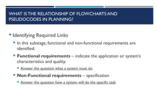
Identifying Required Links
In this substage, functional and non-functional requirements are
identified.
Functional requirements – indicate the application or system’s
characteristics and quality.
Answer the question what a system must do
Non-Functional requirements – specification
Answer the question how a system will do the specific task
13.
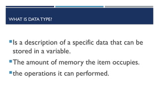
WHAT IS DATATYPE?
Is a description of a specific data that can be
stored in a variable.
The amount of memory the item occupies.
the operations it can performed.
14.
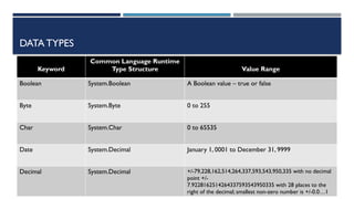
DATA TYPES
Keyword
Common LanguageRuntime
Type Structure Value Range
Boolean System.Boolean A Boolean value – true or false
Byte System.Byte 0 to 255
Char System.Char 0 to 65535
Date System.Decimal January 1, 0001 to December 31, 9999
Decimal System.Decimal +/-79,228,162,514,264,337,593,543,950,335 with no decimal
point +/-
7.9228162514264337593543950335 with 28 places to the
right of the decimal; smallest non-zero number is +/-0.0…1
15.
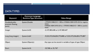
DATA TYPES
Keyword
Common Language
RuntimeTypeStructure Value Range
Double(double-
precision floating
point)
System.Double -179769313486231E + 308 to 4.940656 45841247E-324 for negative
values;
4.940656 45841247E-324 to -179769313486231E + 308 for positive
values
Integer System.Int32 -2,147,483.648 to 2,147,483.647
Long (long integer) System.Int64 -9,223,372,036,854,775,808 to 9,223,372,036,854,775,807
Object System.Object(c) Any type can be stored in variable of type of type Object
Short System.Int16 -32,768, to 32, 767
16.
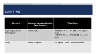
DATA TYPES
Keyword CommonLanguage Runtime
Type Structure
Value Range
Single(single precision
floating point)
System.Single -3.402823E+38 to -1.401298E-45 for negative
values;
-1.401298E-45 to -3.402823E+38 for positive
values
String System.String(class) 0 to approx. 2 billion Unicode characters
17.
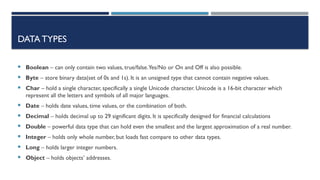
DATA TYPES
Boolean– can only contain two values, true/false.Yes/No or On and Off is also possible.
Byte – store binary data(set of 0s and 1s). It is an unsigned type that cannot contain negative values.
Char – hold a single character, specifically a single Unicode character. Unicode is a 16-bit character which
represent all the letters and symbols of all major languages.
Date – holds date values, time values, or the combination of both.
Decimal – holds decimal up to 29 significant digits. It is specifically designed for financial calculations
Double – powerful data type that can hold even the smallest and the largest approximation of a real number.
Integer – holds only whole number, but loads fast compare to other data types.
Long – holds larger integer numbers.
Object – holds objects’ addresses.
18.
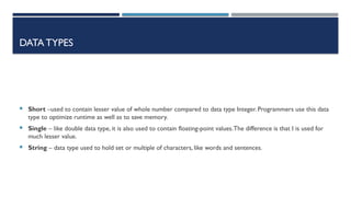
DATA TYPES
Short–used to contain lesser value of whole number compared to data type Integer. Programmers use this data
type to optimize runtime as well as to save memory.
Single – like double data type, it is also used to contain floating-point values.The difference is that I is used for
much lesser value.
String – data type used to hold set or multiple of characters, like words and sentences.
19.
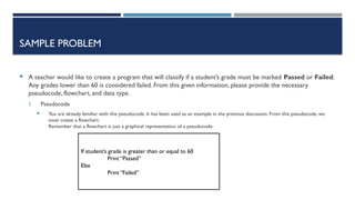
SAMPLE PROBLEM
Ateacher would like to create a program that will classify if a student’s grade must be marked Passed or Failed.
Any grades lower than 60 is considered failed. From this given information, please provide the necessary
pseudocode, flowchart, and data type.
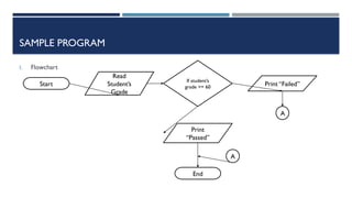
I. Pseudocode
You are already familiar with this pseudocode. It has been used as an example in the previous discussion. From this pseudocode, we
must create a flowchart.
Remember that a flowchart is just a graphical representation of a pseudocode.
If student’s grade is greater than or equal to 60
Print “Passed”
Else
Print “Failed”
SAMPLE PROGRAM
I. DataType
The next step is to identify the variable’s data type. Let us first analyze
the variable, which is the student’s grade.As we know, It can also
contain numbers and is usually in the scale of 0 – 100. the double data
type is the best data type for this variable since a student’s grade is
usually a real number (numbers with decimal places).
22.
KEYTERMS
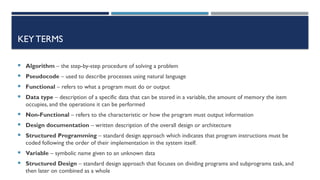
Algorithm –the step-by-step procedure of solving a problem
Pseudocode – used to describe processes using natural language
Functional – refers to what a program must do or output
Data type – description of a specific data that can be stored in a variable, the amount of memory the item
occupies, and the operations it can be performed
Non-Functional – refers to the characteristic or how the program must output information
Design documentation – written description of the overall design or architecture
Structured Programming – standard design approach which indicates that program instructions must be
coded following the order of their implementation in the system itself.
Variable – symbolic name given to an unknown data
Structured Design – standard design approach that focuses on dividing programs and subprograms task, and
then later on combined as a whole
23.
SEATWORK
1. How canan algorithm help in making an efficient program?
2. Why do you think a programmer must create a pseudocode or a flowchart first?
3. What are the four parts of design documentation?
24.
ACTIVITY
Do theactivity on a sheet of paper:
Create a pseudocode and flowchart for a program that will let the user to choose from sphere, cylinder, or cube.
The said program must compute volumes from values inputted by the users.


![Algorithm Design and Problem Solving [Autosaved].pptx](https://cdn.slidesharecdn.com/ss_thumbnails/algorithmdesignandproblemsolvingautosaved-230525024624-6a6fb3b2-thumbnail.jpg?width=640&height=640&fit=bounds)


![Lecture_01-Problem_Solving[1]||ProgrammingFundamental.ppt](https://cdn.slidesharecdn.com/ss_thumbnails/lecture01-problemsolving1-240327053222-8448be2c-thumbnail.jpg?width=640&height=640&fit=bounds)