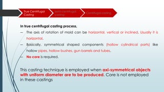
SlideShare a Scribd company logo
Moulding
Moulding
Moulding is the process of making a mould cavity by packing prepared moulding
sand around the pattern and removing the pattern from the mould to form the
mould cavity.
Moulding Sand
Silica Grains Clay Water
90%
1. Green sand
2. Dry sand
3. Loam sand
4. Facing sand
5. Backing sand
6. Parting sand
Moulding Sand
Also called wet state; 8% water, 16 to 30% clay, soft, light and porous
,High damping capacity.
Dry in nature, High strength and rigidity
Fine silica, fine refractories, clay, graphite, fiber and water, becomes very
hard when it is dried
Mixture of silica and dry sand ,used to cover the surface of the pattern
(fine finish) eg. Coal dust mixed with sand
Old sand, can be used repeatedly
Mixture Silica and brick powder, used to avoid the sticking of patterns
while removing (split pattern)
Refers to the sand ability to withstand
the temperature of the liquid metal
being cast without breaking down.
Refractoriness
Flowability is the property of the
sand to respond to the moulding
process so that when rammed it will
flow all around the pattern and
take the desired mould shape.
Flowability
Ability of the sand to be easily
stripped off the casting after it has
solidified.
Collapsibility
Ability of the moulding sand to stick
with walls of the moulding boxes
Adhesiveness
Refers to the sand ability to exhaust
gases
Permeability
Properties of moulding sand
Defects In Casting
1. Gas defects
2. Shrinkage cavities
3. Molding Material Defects
4. Pouring Metal Defects
5. Metallurgical defects
Gas
defects
Shrinkage
cavities
Moulding material
defects
Pouring metal
defects
Metallurgical
defects
1.
2.
3.
Blow holes and open blows
Air Inclusion
Pin Hole Porosity
Gas
defects
Shrinkage
cavities
Moulding material
defects
Pouring metal
defects
Metallurgical
defects
These are the spherical, flattened or elongated cavities present inside
the casting or on the surface. On the surface they are called open
blows and inside, they are called blowholes.
― Inadequate core venting
― Excessive release of gas from core
― Excessive moisture absorption by the
cores
― Low gas permeability of the core sand
― Moisture content of sand too high,
or water released too quickly
― Gas permeability of the sand too low
― Sand temperature too high
― Improve core venting, provide
venting channels
― Reduce moisture content of sand
― Improve gas permeability
― Reduce sand temperature. Install
a sand cooler if necessary
― Dry out cores , thus reducing
absorption of water and reducing
gas pressure
Remedies
Possible causes
Blow holes and open blows
1.
Gas
defects
Shrinkage
cavities
Moulding material
defects
Pouring metal
defects
Metallurgical
defects
2. Air Inclusion
The atmospheric and other gases absorbed by the molten metal in
the furnace, in the ladle, and during the flow in the mould, when not
allowed to escape, would be trapped inside the casting and
weaken it.
― Faulty gating
― Faulty pouring
― Inferior molding or core sand
― Soft ramming of mold
― Rough handling of mold and
core
― Modify gating system
― Improve pouring to minimize
turbulence.
― Use of superior sand of good
strength
― Provide hard, ramming
Remedies
Possible causes
Gas
defects
Shrinkage
cavities
Moulding material
defects
Pouring metal
defects
Metallurgical
defects
3. Pin Hole Porosity
Agglomeration of small, rounded cavities up to around 5
mm in size. Surface of the cavities mostly smooth and polished.
― High pouring temperature
― Gas dissolved in metal charge
― Molten metal not properly
degassed
― Slow solidification of casting
― High moisture and low permeability
in mold
― Regulate pouring temperature
― Control metal composition
― Ensure effective degassing
― Modify gating and risering
― Reduce moisture and increase
permeability of mold
Remedies
Possible causes
Gas
defects
Shrinkage
cavities
Moulding material
defects
Pouring metal
defects
Metallurgical
defects
These are caused by liquid shrinkage occurring during the
solidification of the casting. To compensate for this,
proper feeding of liquid metal is required. For this reason
risers are placed at the appropriate places in the mold.
Sprues may be too thin, too long or not attached in the
proper location, causing shrinkage cavities. It is
recommended to use thick sprues to avoid shrinkage
cavities.
― Faulty gating and risering system
― Improper chilling
― Ensure proper directional
solidification by modifying
gating risering and chilling
Remedies
Possible causes
Gas
defects
Shrinkage
cavities
Moulding material
defects
Pouring metal
defects
Metallurgical
defects
1.
2.
3.
Run out
Cuts and washes
Metal penetration
4. Fusion
5. Swell
Gas
defects
Shrinkage
cavities
Moulding material
defects
Pouring metal
defects
Metallurgical
defects
A run out is when the liquid metal leaks out of the mold
because of a faulty mold or flask. Scabs are a thin layer of
metal that sits proud of the casting.
― Faulty molding
― Defective molding boxes
― Improving molding technique
― Change the defective
molding boxes
Remedies
Possible causes
Run out
1.
Gas
defects
Shrinkage
cavities
Moulding material
defects
Pouring metal
defects
Metallurgical
defects
These appear as rough spots and areas of excess metal,
and are caused by erosion of molding sand by the
flowing metal. This is caused by the molding sand not
having enough strength and the molten metal flowing at
high velocity.
― Low strength of mold and
core
― Lack of binders in facing
and core sand
― Faulty gating
― Improve mold and core
strength
― Add more binders to
facing and sand
― Improve gating
Remedies
Possible causes
Cuts and washes
2.
Gas
defects
Shrinkage
cavities
Moulding material
defects
Pouring metal
defects
Metallurgical
defects
Metal penetration
3.
When molten metal enters into the gaps between sand
grains, the result is a rough casting surface. This occurs
because the sand is coarse or no mold wash was applied
on the surface of the mold. The coarser the sand grains
more the metal penetration.
― Large grain size
― Soft ramming of mold
― Molding sand or core has
low strength
― Molding sand or core has
high permeability
― Pouring temperature of
metal too high
― Use sand having finer
grain size
― Provide hard ramming
― Suitably adjust pouring
temperature
Remedies
Possible causes
Gas
defects
Shrinkage
cavities
Moulding material
defects
Pouring metal
defects
Metallurgical
defects
Fusion
4.
This is caused by the fusion of the sand grains with the
molten metal, giving a brittle, glassy appearance on the
casting surface. The main reason for this is that the clay or
the sand particles are of lower refractoriness or that the
pouring temperature is too high.
― Low refractoriness in
molding sand
― Faulty gating
― Too high pouring
temperature of metal
― Poor facing sand
― Improve refractoriness of sand
― Modify gating system
― Use lower pouring temperature
― Improve quality of facing sand
Remedies
Possible causes
Gas
defects
Shrinkage
cavities
Moulding material
defects
Pouring metal
defects
Metallurgical
defects
Swell
5.
Enlargement of the mould cavity by metal pressures, results – localized or
overall enlargement of castings. A proper ramming of the mold will correct this
defect.
― Too soft ramming of mold
― Low strength of mold and core
― Mold not properly supported
― Provide hard ramming
― Increase strength of both mold and
core
Remedies
Possible causes
Gas
defects
Shrinkage
cavities
Moulding material
defects
Pouring metal
defects
Metallurgical
defects
1.
2.
Slag Inclusion
Mis -runs
3. Cold Shuts
Gas
defects
Shrinkage
cavities
Moulding material
defects
Pouring metal
defects
Metallurgical
defects
Slag Inclusion
1.
As, in most cases, this defect is related to furnace or melt
treatment slag it can occur in all casting materials,
independent of the molding or casting process. This
defect is often observed on casting surfaces on top in the
mold, cores, and protruding mold sections. These non-
metallic inclusions can be accompanied by gas bubbles.
― Addition of flux/flow in
molten metal
― Adoption of some of the slag
trapping methods like pouring
basin screens and runner
extensions.
Remedies
Possible causes
Gas
defects
Shrinkage
cavities
Moulding material
defects
Pouring metal
defects
Metallurgical
defects
Mis-runs
2.
A mis-run is caused when the metal is unable to fill the
mold cavity completely and thus leaves unfilled cavities.
A mis-run results when the metal is too cold to flow to the
extremities of the mold cavity before freezing. Long, thin
sections are subject to this defect and should be avoided
in casting design.
― Lack of fluidity in the
molten metal
― Metal freezes before
mold is filled
― Faulty design
― Fluidity can be improved by
changing the composition of t
the metal
― Adjust proper pouring
temperature
― Modify design
Remedies
Possible causes
Gas
defects
Shrinkage
cavities
Moulding material
defects
Pouring metal
defects
Metallurgical
defects
Cold Shuts
3.
A cold shut is caused when two streams while meeting in the mold cavity,
do not fuse together properly thus forming a discontinuity in the casting.
When the molten metal is poured into the mold cavity through more-
than-one gate, multiple liquid fronts will have to flow together and
become one solid. If the flowing metal fronts are too cool, they may not
flow together, but will leave a seam in the part. Such a seam is called a
cold shut, and can be prevented by assuring sufficient superheat in the
poured metal and thick enough walls in the casting design.
― Lack of fluidity in the
molten metal
― Faulty design
― Fluidity can be improved by
changing the composition of
the metal
― Adjust proper pouring
temperature
― Modify design
Remedies
Possible causes
Gas
defects
Shrinkage
cavities
Moulding material
defects
Pouring metal
defects
Metallurgical
defects
Hot tears
1.
If a section begins to shrink while still hot and there is not a
sufficient supply of liquid metal, the resulting internal stress will
tear the metal. This is because while hot the metal has relatively
low strength.
― Lack of collapsibility
of core
― Lack of collapsibility
of mold
― Faulty design
― Improve core collapsibility.
― Improve mold collapsibility
― Modify casting design.
Remedies
Possible causes
Die Casting
Die casting is a permanent-mold
casting process in which the
molten metal is injected into the
mold cavity under high pressure.
Typical pressures are 7 to 350
MPa.
The pressure is maintained during
solidification, after which the
mold is opened and the part is
removed. Molds in this casting
operation are called dies; hence
the name die casting.
Die Casting
1) Hot Chamber Die Casting 2) Cold Chamber Die Casting
Classification
Disadvantage
Advantage
― Hollow shapes are not readily
casted because of the high metal
pressure.
― Limited sizes of the products can
be produced based on the
availability of the equipment.
― High melting temperature alloys
are practically not die casted.
─ High production rate
─ High accuracy in part dimensions
─ Smooth surface finish for minimum
mechanical finishing
─ Ability to make many intricate
parts such as hole opening slot
trademark number etc.
─ Much thinner wall sections can
be produced which can’t be
produced by other casting
methods.
Die casting process is preferred for nonferrous metal parts of intricate shapes.
Examples of products are automobiles appliances, hand tools, computer
peripherals, toys, optical and photographic equipment etc.
Application
In hot-chamber die casting, the metal is melted in a container
attached to the machine, and a piston is used to inject the
liquid metal under high pressure into the die. Typical injection
pressures are 7 to 35 MPa.
Production rates up to 500 parts per hour are not uncommon.
Hot-chamber die casting imposes a special hardship on the
injection system because much of it is submerged in the molten
metal. The process is therefore limited in its applications to low
melting-point metals that do not chemically attack the plunger
and other mechanical components. The metals include zinc,
tin, lead, and sometimes magnesium.
Hot Chamber Die Casting
Cycle in hot chamber
casting:
(1) with die closed and
plunger withdrawn, molten
metal flows into the chamber;
(2) plunger forces metal in
chamber to flow into die,
maintaining pressure during
Cooling and solidification;
(3) plunger is withdrawn, die is
opened, and solidified part is
ejected. Finished part is
shown in (4).
Process Cycle
In cold-chamber die casting machines, molten metal is poured
into an unheated chamber from an external melting container,
and a piston is used to inject the metal under high pressure into
the die cavity. Injection pressures used in these machines are
typically 14 to 140 MPa.
Compared to hot-chamber machines, cycle rates are not usually
as fast because of the need to ladle the liquid metal into the
chamber from an external source. Nevertheless, this casting
process is a high production operation. Cold-chamber machines
are typically used for casting aluminum, brass, and magnesium
alloys. Low-melting-point alloys (zinc, tin, lead) can also be cast
on cold-chamber machines, but the advantages of the hot-
chamber process usually favour its use on these metals.
Cold Chamber Die Casting
Process Cycle
Cycle in cold-chamber
casting:
(1) with die closed and
ram withdrawn, molten
metal is poured into the
chamber;
(2) ram forces metal to
flow into die, maintaining
pressure during cooling
and solidification
(3) ram is withdrawn, die
is opened, and part is
ejected.
Centrifugal
Casting
In this process we make use of the centrifugal force which is directed
away from the centre and exists at high speeds. In this method the
mould is rotated about its central axis and there exists a continuous
pressure as metal is solidifying, slag being lighter gets segregated
towards the centre.
Centrifugal Casting
True Centrifugal
Casting
Semi-centrifugal
casting
Centrifugal casting
In true centrifugal casting process,
― The axis of rotation of mold can be horizontal, vertical or inclined. Usually it is
horizontal.
― Basically, symmetrical shaped components (hollow cylindrical parts) like
hollow pipes, hollow bushes, gun barrels and tubes.
― No core is required.
This casting technique is employed when axi-symmetrical objects
with uniform diameter are to be produced. Core is not employed
in these castings
Advantages of true centrifugal casting
1) Relatively very light impurities move inwards towards centre. So they can be
removed easily.
2) These castings have a directional solidification starting from outside to inside.
3) Central core is not required for making a hole or pipe
4) Employment of gates and risers is not required
5) This technique is best suited for the mass production of symmetrical objects.
Disadvantages of true centrifugal casting
1) Centrifugal castings require very high investments.
2) Skilled labours are to be employed for this process.
3) Only some shapes can be generated by this casting process.
Applications
1) Bearings for machines
2) Pipes
3) Rings and other annular components
True Centrifugal
Casting
Semi-centrifugal
casting
Centrifugal casting
― It is similar to true centrifugal casting but
only with a difference that a central
core is used to form the inner surface.
This casting process is generally used
for articles which are more complicated
than those possible in true centrifugal
casting, but are axi-symmetric in nature.
― Semi centrifugal casting is employed for
casting gear blanks, sheaves, and
wheels etc.
― low spinning speeds can be used
speeds ranging between 180 to 200
RPM is recommended. These castings
are normally prepared in vertical
machines. The mold cavity is arranged
with in the mold so that its central axis is
vertical and concentric with the axis of
rotation.
Article produced
by semicentrifugal
casting process
1) Number of molds can be stacked together, one over the other
can be fed by a common central sprue in order to produce
more than one casting at a time.
2) Similar to true centrifugal casting it ensures purity and density of
the product poorer structure forms the center of the casting so
this can be machined off.
Advantages Semi Centrifugal Casting
True Centrifugal
Casting
Semi-centrifugal
casting
Centrifugal casting
― This type of casting method is used for casting unsymmetrical castings in
groups. This is done in groups for obtaining balance of whole casting.
― In these castings the axis of mold doesn’t coincide with each other to induce
the pressure on molds the casting rotated at the center.
― Feeding to the mold cavities is done by central sprue by the action of
centrifugal forces.
1) Ensures better quality.
2) Castings when generated on large scale will be
economical.
3) Cleaning and repair cost of the castings can be
reduced.
4) Rejection percentage is very low
Advantages Centrifugal Casting
Investment
Casting
1) The investment casting process initiates with the production of wax replicas
or patterns of the required shape of castings. Each and every casting
requires a pattern to be produced. Wax or polystyrene is made used as the
injecting material. The assembly of large number of patterns are made and
attached to a wax sprue centrally.
2) Metallic dies are used to prepare the patterns.
3) The pattern is immersed in refractory slurry which completely surrounds it and
gets set at room temperature forming the mold. The mold is further heated,
so that the pattern melts and flows out, leaving the required cavity behind.
After heating, the mold gets further hardened and molten metal is poured
while it is still hot. After the casting gets solidified, the mold is broken and it is
taken out.
Investment Casting
Investment Casting
Advantages Investment Casting
1) Closed dimensional tolerances and intricate geometries are easily obtained.
2) A single process gives good surface finish
3) Alloys with higher melting points can also be easily cast
Limitation
1) Expensive process since it uses the wax, which increases the cost.
2) The cross section of molds being thin, the process is limited by size and mass of
casting.
3) Removal of the wax from the mold again adds up time and cost.
Comparison of Casting Process
Process Merits Limitation
Sand Almost any metal is cast; no limit to
size, or weight; low tooling cost
Some finishing required, wide
tolerance
Die Excellent dimensional accuracy
and surface finish; high production
rate
Die cost is high; part size limited;
usually limited to nonferrous
metals
Centrifugal Large cylindrical parts with good
quality; high production rate
Equipment is expensive, part
shape limited
Investment Intricate shapes; excellent surface
finish and accuracy; almost any
metal cast
Part size limited; expensive
patterns, molds and labour.

More Related Content

Similar to Lectures_MP_Molding (1).pdf

SAND CASTING PRESENTATION_SIVAKRISHNA PS_S2 ME_ROLL NO. 62.pptx
SAND CASTING PRESENTATION_SIVAKRISHNA PS_S2 ME_ROLL NO. 62.pptxSAND CASTING PRESENTATION_SIVAKRISHNA PS_S2 ME_ROLL NO. 62.pptx
SAND CASTING PRESENTATION_SIVAKRISHNA PS_S2 ME_ROLL NO. 62.pptx
JefinJoseph7
 
Metal casting defects 1
Metal casting defects 1Metal casting defects 1
Metal casting defects 1
Digvijaysinh Gohil
 
ME8351 Unit 1 class notes- Pattern
ME8351 Unit 1 class notes- PatternME8351 Unit 1 class notes- Pattern
ME8351 Unit 1 class notes- Pattern
Pravinkumar
 
Casting defects by yaser elkelawy
Casting defects by yaser elkelawyCasting defects by yaser elkelawy
Casting defects by yaser elkelawy
Yasser Mohamed abbas elkelawy
 
11. Lecture 20 Casting..pptx
11.  Lecture 20 Casting..pptx11.  Lecture 20 Casting..pptx
11. Lecture 20 Casting..pptx
ssuser7a0070
 
Sand casting of metals - Gating system for sand casting mould
Sand casting of metals - Gating system for sand casting mouldSand casting of metals - Gating system for sand casting mould
Sand casting of metals - Gating system for sand casting mould
Amruta Rane
 
Module 1 (1).pptx
Module 1 (1).pptxModule 1 (1).pptx
Module 1 (1).pptx
GibinGeorge23
 
Casting by amjad
Casting by amjadCasting by amjad
Casting by amjad
77amjad
 
Manufacturing process sessional casting defacts
Manufacturing process sessional casting defactsManufacturing process sessional casting defacts
Manufacturing process sessional casting defacts
222020651
 
History of sand casting
History of sand castingHistory of sand casting
Casting defects
Casting defectsCasting defects
Casting defects
Gulfam Hussain
 
12.casting of metals
12.casting of metals12.casting of metals
12.casting of metals
Bilal
 
Manufacturing processes
Manufacturing processesManufacturing processes
Manufacturing processes
Akhil Varghese
 
12chapter_2_a_fundamental_of_metal_CASTING_FULL_final_material.ppt
12chapter_2_a_fundamental_of_metal_CASTING_FULL_final_material.ppt12chapter_2_a_fundamental_of_metal_CASTING_FULL_final_material.ppt
12chapter_2_a_fundamental_of_metal_CASTING_FULL_final_material.ppt
KaleabAdane
 
casting process ( MP 2 / SEM 4 / GTU )
casting process ( MP 2 / SEM 4 / GTU )casting process ( MP 2 / SEM 4 / GTU )
casting process ( MP 2 / SEM 4 / GTU )
tejaspatel1997
 
Manufacturing Processes
Manufacturing ProcessesManufacturing Processes
Manufacturing Processes
Akshaya Chavan
 
Report on shell molding
Report on shell moldingReport on shell molding
Report on shell molding
Pawan Kumar
 

Similar to Lectures_MP_Molding (1).pdf (20)

SAND CASTING PRESENTATION_SIVAKRISHNA PS_S2 ME_ROLL NO. 62.pptx
SAND CASTING PRESENTATION_SIVAKRISHNA PS_S2 ME_ROLL NO. 62.pptxSAND CASTING PRESENTATION_SIVAKRISHNA PS_S2 ME_ROLL NO. 62.pptx
SAND CASTING PRESENTATION_SIVAKRISHNA PS_S2 ME_ROLL NO. 62.pptx
 
Metal casting defects 1
Metal casting defects 1Metal casting defects 1
Metal casting defects 1
 
ME8351 Unit 1 class notes- Pattern
ME8351 Unit 1 class notes- PatternME8351 Unit 1 class notes- Pattern
ME8351 Unit 1 class notes- Pattern
 
Casting defects by yaser elkelawy
Casting defects by yaser elkelawyCasting defects by yaser elkelawy
Casting defects by yaser elkelawy
 
Defects
DefectsDefects
Defects
 
11. Lecture 20 Casting..pptx
11.  Lecture 20 Casting..pptx11.  Lecture 20 Casting..pptx
11. Lecture 20 Casting..pptx
 
10 surface blowholes2
10 surface blowholes210 surface blowholes2
10 surface blowholes2
 
Sand casting of metals - Gating system for sand casting mould
Sand casting of metals - Gating system for sand casting mouldSand casting of metals - Gating system for sand casting mould
Sand casting of metals - Gating system for sand casting mould
 
Module 1 (1).pptx
Module 1 (1).pptxModule 1 (1).pptx
Module 1 (1).pptx
 
Casting by amjad
Casting by amjadCasting by amjad
Casting by amjad
 
Manufacturing process sessional casting defacts
Manufacturing process sessional casting defactsManufacturing process sessional casting defacts
Manufacturing process sessional casting defacts
 
History of sand casting
History of sand castingHistory of sand casting
History of sand casting
 
Casting defects
Casting defectsCasting defects
Casting defects
 
Casting defects
Casting defectsCasting defects
Casting defects
 
12.casting of metals
12.casting of metals12.casting of metals
12.casting of metals
 
Manufacturing processes
Manufacturing processesManufacturing processes
Manufacturing processes
 
12chapter_2_a_fundamental_of_metal_CASTING_FULL_final_material.ppt
12chapter_2_a_fundamental_of_metal_CASTING_FULL_final_material.ppt12chapter_2_a_fundamental_of_metal_CASTING_FULL_final_material.ppt
12chapter_2_a_fundamental_of_metal_CASTING_FULL_final_material.ppt
 
casting process ( MP 2 / SEM 4 / GTU )
casting process ( MP 2 / SEM 4 / GTU )casting process ( MP 2 / SEM 4 / GTU )
casting process ( MP 2 / SEM 4 / GTU )
 
Manufacturing Processes
Manufacturing ProcessesManufacturing Processes
Manufacturing Processes
 
Report on shell molding
Report on shell moldingReport on shell molding
Report on shell molding
 

Recently uploaded

Sachpazis:Terzaghi Bearing Capacity Estimation in simple terms with Calculati...
Sachpazis:Terzaghi Bearing Capacity Estimation in simple terms with Calculati...Sachpazis:Terzaghi Bearing Capacity Estimation in simple terms with Calculati...
Sachpazis:Terzaghi Bearing Capacity Estimation in simple terms with Calculati...
Dr.Costas Sachpazis
 
Steel & Timber Design according to British Standard
Steel & Timber Design according to British StandardSteel & Timber Design according to British Standard
Steel & Timber Design according to British Standard
AkolbilaEmmanuel1
 
Recycled Concrete Aggregate in Construction Part III
Recycled Concrete Aggregate in Construction Part IIIRecycled Concrete Aggregate in Construction Part III
Recycled Concrete Aggregate in Construction Part III
Aditya Rajan Patra
 
PPT on GRP pipes manufacturing and testing
PPT on GRP pipes manufacturing and testingPPT on GRP pipes manufacturing and testing
PPT on GRP pipes manufacturing and testing
anoopmanoharan2
 
Planning Of Procurement o different goods and services
Planning Of Procurement o different goods and servicesPlanning Of Procurement o different goods and services
Planning Of Procurement o different goods and services
JoytuBarua2
 
Nuclear Power Economics and Structuring 2024
Nuclear Power Economics and Structuring 2024Nuclear Power Economics and Structuring 2024
Nuclear Power Economics and Structuring 2024
Massimo Talia
 
一比一原版(IIT毕业证)伊利诺伊理工大学毕业证成绩单专业办理
一比一原版(IIT毕业证)伊利诺伊理工大学毕业证成绩单专业办理一比一原版(IIT毕业证)伊利诺伊理工大学毕业证成绩单专业办理
一比一原版(IIT毕业证)伊利诺伊理工大学毕业证成绩单专业办理
zwunae
 
6th International Conference on Machine Learning & Applications (CMLA 2024)
6th International Conference on Machine Learning & Applications (CMLA 2024)6th International Conference on Machine Learning & Applications (CMLA 2024)
6th International Conference on Machine Learning & Applications (CMLA 2024)
ClaraZara1
 
Investor-Presentation-Q1FY2024 investor presentation document.pptx
Investor-Presentation-Q1FY2024 investor presentation document.pptxInvestor-Presentation-Q1FY2024 investor presentation document.pptx
Investor-Presentation-Q1FY2024 investor presentation document.pptx
AmarGB2
 
Pile Foundation by Venkatesh Taduvai (Sub Geotechnical Engineering II)-conver...
Pile Foundation by Venkatesh Taduvai (Sub Geotechnical Engineering II)-conver...Pile Foundation by Venkatesh Taduvai (Sub Geotechnical Engineering II)-conver...
Pile Foundation by Venkatesh Taduvai (Sub Geotechnical Engineering II)-conver...
AJAYKUMARPUND1
 
Hierarchical Digital Twin of a Naval Power System
Hierarchical Digital Twin of a Naval Power SystemHierarchical Digital Twin of a Naval Power System
Hierarchical Digital Twin of a Naval Power System
Kerry Sado
 
CW RADAR, FMCW RADAR, FMCW ALTIMETER, AND THEIR PARAMETERS
CW RADAR, FMCW RADAR, FMCW ALTIMETER, AND THEIR PARAMETERSCW RADAR, FMCW RADAR, FMCW ALTIMETER, AND THEIR PARAMETERS
CW RADAR, FMCW RADAR, FMCW ALTIMETER, AND THEIR PARAMETERS
veerababupersonal22
 
一比一原版(SFU毕业证)西蒙菲莎大学毕业证成绩单如何办理
一比一原版(SFU毕业证)西蒙菲莎大学毕业证成绩单如何办理一比一原版(SFU毕业证)西蒙菲莎大学毕业证成绩单如何办理
一比一原版(SFU毕业证)西蒙菲莎大学毕业证成绩单如何办理
bakpo1
 
Heap Sort (SS).ppt FOR ENGINEERING GRADUATES, BCA, MCA, MTECH, BSC STUDENTS
Heap Sort (SS).ppt FOR ENGINEERING GRADUATES, BCA, MCA, MTECH, BSC STUDENTSHeap Sort (SS).ppt FOR ENGINEERING GRADUATES, BCA, MCA, MTECH, BSC STUDENTS
Heap Sort (SS).ppt FOR ENGINEERING GRADUATES, BCA, MCA, MTECH, BSC STUDENTS
Soumen Santra
 
Water Industry Process Automation and Control Monthly - May 2024.pdf
Water Industry Process Automation and Control Monthly - May 2024.pdfWater Industry Process Automation and Control Monthly - May 2024.pdf
Water Industry Process Automation and Control Monthly - May 2024.pdf
Water Industry Process Automation & Control
 
Railway Signalling Principles Edition 3.pdf
Railway Signalling Principles Edition 3.pdfRailway Signalling Principles Edition 3.pdf
Railway Signalling Principles Edition 3.pdf
TeeVichai
 
Building Electrical System Design & Installation
Building Electrical System Design & InstallationBuilding Electrical System Design & Installation
Building Electrical System Design & Installation
symbo111
 
Fundamentals of Induction Motor Drives.pptx
Fundamentals of Induction Motor Drives.pptxFundamentals of Induction Motor Drives.pptx
Fundamentals of Induction Motor Drives.pptx
manasideore6
 
Hybrid optimization of pumped hydro system and solar- Engr. Abdul-Azeez.pdf
Hybrid optimization of pumped hydro system and solar- Engr. Abdul-Azeez.pdfHybrid optimization of pumped hydro system and solar- Engr. Abdul-Azeez.pdf
Hybrid optimization of pumped hydro system and solar- Engr. Abdul-Azeez.pdf
fxintegritypublishin
 
RAT: Retrieval Augmented Thoughts Elicit Context-Aware Reasoning in Long-Hori...
RAT: Retrieval Augmented Thoughts Elicit Context-Aware Reasoning in Long-Hori...RAT: Retrieval Augmented Thoughts Elicit Context-Aware Reasoning in Long-Hori...
RAT: Retrieval Augmented Thoughts Elicit Context-Aware Reasoning in Long-Hori...
thanhdowork
 

Recently uploaded (20)

Sachpazis:Terzaghi Bearing Capacity Estimation in simple terms with Calculati...
Sachpazis:Terzaghi Bearing Capacity Estimation in simple terms with Calculati...Sachpazis:Terzaghi Bearing Capacity Estimation in simple terms with Calculati...
Sachpazis:Terzaghi Bearing Capacity Estimation in simple terms with Calculati...
 
Steel & Timber Design according to British Standard
Steel & Timber Design according to British StandardSteel & Timber Design according to British Standard
Steel & Timber Design according to British Standard
 
Recycled Concrete Aggregate in Construction Part III
Recycled Concrete Aggregate in Construction Part IIIRecycled Concrete Aggregate in Construction Part III
Recycled Concrete Aggregate in Construction Part III
 
PPT on GRP pipes manufacturing and testing
PPT on GRP pipes manufacturing and testingPPT on GRP pipes manufacturing and testing
PPT on GRP pipes manufacturing and testing
 
Planning Of Procurement o different goods and services
Planning Of Procurement o different goods and servicesPlanning Of Procurement o different goods and services
Planning Of Procurement o different goods and services
 
Nuclear Power Economics and Structuring 2024
Nuclear Power Economics and Structuring 2024Nuclear Power Economics and Structuring 2024
Nuclear Power Economics and Structuring 2024
 
一比一原版(IIT毕业证)伊利诺伊理工大学毕业证成绩单专业办理
一比一原版(IIT毕业证)伊利诺伊理工大学毕业证成绩单专业办理一比一原版(IIT毕业证)伊利诺伊理工大学毕业证成绩单专业办理
一比一原版(IIT毕业证)伊利诺伊理工大学毕业证成绩单专业办理
 
6th International Conference on Machine Learning & Applications (CMLA 2024)
6th International Conference on Machine Learning & Applications (CMLA 2024)6th International Conference on Machine Learning & Applications (CMLA 2024)
6th International Conference on Machine Learning & Applications (CMLA 2024)
 
Investor-Presentation-Q1FY2024 investor presentation document.pptx
Investor-Presentation-Q1FY2024 investor presentation document.pptxInvestor-Presentation-Q1FY2024 investor presentation document.pptx
Investor-Presentation-Q1FY2024 investor presentation document.pptx
 
Pile Foundation by Venkatesh Taduvai (Sub Geotechnical Engineering II)-conver...
Pile Foundation by Venkatesh Taduvai (Sub Geotechnical Engineering II)-conver...Pile Foundation by Venkatesh Taduvai (Sub Geotechnical Engineering II)-conver...
Pile Foundation by Venkatesh Taduvai (Sub Geotechnical Engineering II)-conver...
 
Hierarchical Digital Twin of a Naval Power System
Hierarchical Digital Twin of a Naval Power SystemHierarchical Digital Twin of a Naval Power System
Hierarchical Digital Twin of a Naval Power System
 
CW RADAR, FMCW RADAR, FMCW ALTIMETER, AND THEIR PARAMETERS
CW RADAR, FMCW RADAR, FMCW ALTIMETER, AND THEIR PARAMETERSCW RADAR, FMCW RADAR, FMCW ALTIMETER, AND THEIR PARAMETERS
CW RADAR, FMCW RADAR, FMCW ALTIMETER, AND THEIR PARAMETERS
 
一比一原版(SFU毕业证)西蒙菲莎大学毕业证成绩单如何办理
一比一原版(SFU毕业证)西蒙菲莎大学毕业证成绩单如何办理一比一原版(SFU毕业证)西蒙菲莎大学毕业证成绩单如何办理
一比一原版(SFU毕业证)西蒙菲莎大学毕业证成绩单如何办理
 
Heap Sort (SS).ppt FOR ENGINEERING GRADUATES, BCA, MCA, MTECH, BSC STUDENTS
Heap Sort (SS).ppt FOR ENGINEERING GRADUATES, BCA, MCA, MTECH, BSC STUDENTSHeap Sort (SS).ppt FOR ENGINEERING GRADUATES, BCA, MCA, MTECH, BSC STUDENTS
Heap Sort (SS).ppt FOR ENGINEERING GRADUATES, BCA, MCA, MTECH, BSC STUDENTS
 
Water Industry Process Automation and Control Monthly - May 2024.pdf
Water Industry Process Automation and Control Monthly - May 2024.pdfWater Industry Process Automation and Control Monthly - May 2024.pdf
Water Industry Process Automation and Control Monthly - May 2024.pdf
 
Railway Signalling Principles Edition 3.pdf
Railway Signalling Principles Edition 3.pdfRailway Signalling Principles Edition 3.pdf
Railway Signalling Principles Edition 3.pdf
 
Building Electrical System Design & Installation
Building Electrical System Design & InstallationBuilding Electrical System Design & Installation
Building Electrical System Design & Installation
 
Fundamentals of Induction Motor Drives.pptx
Fundamentals of Induction Motor Drives.pptxFundamentals of Induction Motor Drives.pptx
Fundamentals of Induction Motor Drives.pptx
 
Hybrid optimization of pumped hydro system and solar- Engr. Abdul-Azeez.pdf
Hybrid optimization of pumped hydro system and solar- Engr. Abdul-Azeez.pdfHybrid optimization of pumped hydro system and solar- Engr. Abdul-Azeez.pdf
Hybrid optimization of pumped hydro system and solar- Engr. Abdul-Azeez.pdf
 
RAT: Retrieval Augmented Thoughts Elicit Context-Aware Reasoning in Long-Hori...
RAT: Retrieval Augmented Thoughts Elicit Context-Aware Reasoning in Long-Hori...RAT: Retrieval Augmented Thoughts Elicit Context-Aware Reasoning in Long-Hori...
RAT: Retrieval Augmented Thoughts Elicit Context-Aware Reasoning in Long-Hori...
 

Lectures_MP_Molding (1).pdf

  • 2. Moulding Moulding is the process of making a mould cavity by packing prepared moulding sand around the pattern and removing the pattern from the mould to form the mould cavity. Moulding Sand Silica Grains Clay Water 90%
  • 3. 1. Green sand 2. Dry sand 3. Loam sand 4. Facing sand 5. Backing sand 6. Parting sand Moulding Sand Also called wet state; 8% water, 16 to 30% clay, soft, light and porous ,High damping capacity. Dry in nature, High strength and rigidity Fine silica, fine refractories, clay, graphite, fiber and water, becomes very hard when it is dried Mixture of silica and dry sand ,used to cover the surface of the pattern (fine finish) eg. Coal dust mixed with sand Old sand, can be used repeatedly Mixture Silica and brick powder, used to avoid the sticking of patterns while removing (split pattern)
  • 4. Refers to the sand ability to withstand the temperature of the liquid metal being cast without breaking down. Refractoriness Flowability is the property of the sand to respond to the moulding process so that when rammed it will flow all around the pattern and take the desired mould shape. Flowability Ability of the sand to be easily stripped off the casting after it has solidified. Collapsibility Ability of the moulding sand to stick with walls of the moulding boxes Adhesiveness Refers to the sand ability to exhaust gases Permeability Properties of moulding sand
  • 5. Defects In Casting 1. Gas defects 2. Shrinkage cavities 3. Molding Material Defects 4. Pouring Metal Defects 5. Metallurgical defects
  • 7. Gas defects Shrinkage cavities Moulding material defects Pouring metal defects Metallurgical defects These are the spherical, flattened or elongated cavities present inside the casting or on the surface. On the surface they are called open blows and inside, they are called blowholes. ― Inadequate core venting ― Excessive release of gas from core ― Excessive moisture absorption by the cores ― Low gas permeability of the core sand ― Moisture content of sand too high, or water released too quickly ― Gas permeability of the sand too low ― Sand temperature too high ― Improve core venting, provide venting channels ― Reduce moisture content of sand ― Improve gas permeability ― Reduce sand temperature. Install a sand cooler if necessary ― Dry out cores , thus reducing absorption of water and reducing gas pressure Remedies Possible causes Blow holes and open blows 1.
  • 8. Gas defects Shrinkage cavities Moulding material defects Pouring metal defects Metallurgical defects 2. Air Inclusion The atmospheric and other gases absorbed by the molten metal in the furnace, in the ladle, and during the flow in the mould, when not allowed to escape, would be trapped inside the casting and weaken it. ― Faulty gating ― Faulty pouring ― Inferior molding or core sand ― Soft ramming of mold ― Rough handling of mold and core ― Modify gating system ― Improve pouring to minimize turbulence. ― Use of superior sand of good strength ― Provide hard, ramming Remedies Possible causes
  • 9. Gas defects Shrinkage cavities Moulding material defects Pouring metal defects Metallurgical defects 3. Pin Hole Porosity Agglomeration of small, rounded cavities up to around 5 mm in size. Surface of the cavities mostly smooth and polished. ― High pouring temperature ― Gas dissolved in metal charge ― Molten metal not properly degassed ― Slow solidification of casting ― High moisture and low permeability in mold ― Regulate pouring temperature ― Control metal composition ― Ensure effective degassing ― Modify gating and risering ― Reduce moisture and increase permeability of mold Remedies Possible causes
  • 10. Gas defects Shrinkage cavities Moulding material defects Pouring metal defects Metallurgical defects These are caused by liquid shrinkage occurring during the solidification of the casting. To compensate for this, proper feeding of liquid metal is required. For this reason risers are placed at the appropriate places in the mold. Sprues may be too thin, too long or not attached in the proper location, causing shrinkage cavities. It is recommended to use thick sprues to avoid shrinkage cavities. ― Faulty gating and risering system ― Improper chilling ― Ensure proper directional solidification by modifying gating risering and chilling Remedies Possible causes
  • 12. Gas defects Shrinkage cavities Moulding material defects Pouring metal defects Metallurgical defects A run out is when the liquid metal leaks out of the mold because of a faulty mold or flask. Scabs are a thin layer of metal that sits proud of the casting. ― Faulty molding ― Defective molding boxes ― Improving molding technique ― Change the defective molding boxes Remedies Possible causes Run out 1.
  • 13. Gas defects Shrinkage cavities Moulding material defects Pouring metal defects Metallurgical defects These appear as rough spots and areas of excess metal, and are caused by erosion of molding sand by the flowing metal. This is caused by the molding sand not having enough strength and the molten metal flowing at high velocity. ― Low strength of mold and core ― Lack of binders in facing and core sand ― Faulty gating ― Improve mold and core strength ― Add more binders to facing and sand ― Improve gating Remedies Possible causes Cuts and washes 2.
  • 14. Gas defects Shrinkage cavities Moulding material defects Pouring metal defects Metallurgical defects Metal penetration 3. When molten metal enters into the gaps between sand grains, the result is a rough casting surface. This occurs because the sand is coarse or no mold wash was applied on the surface of the mold. The coarser the sand grains more the metal penetration. ― Large grain size ― Soft ramming of mold ― Molding sand or core has low strength ― Molding sand or core has high permeability ― Pouring temperature of metal too high ― Use sand having finer grain size ― Provide hard ramming ― Suitably adjust pouring temperature Remedies Possible causes
  • 15. Gas defects Shrinkage cavities Moulding material defects Pouring metal defects Metallurgical defects Fusion 4. This is caused by the fusion of the sand grains with the molten metal, giving a brittle, glassy appearance on the casting surface. The main reason for this is that the clay or the sand particles are of lower refractoriness or that the pouring temperature is too high. ― Low refractoriness in molding sand ― Faulty gating ― Too high pouring temperature of metal ― Poor facing sand ― Improve refractoriness of sand ― Modify gating system ― Use lower pouring temperature ― Improve quality of facing sand Remedies Possible causes
  • 16. Gas defects Shrinkage cavities Moulding material defects Pouring metal defects Metallurgical defects Swell 5. Enlargement of the mould cavity by metal pressures, results – localized or overall enlargement of castings. A proper ramming of the mold will correct this defect. ― Too soft ramming of mold ― Low strength of mold and core ― Mold not properly supported ― Provide hard ramming ― Increase strength of both mold and core Remedies Possible causes
  • 18. Gas defects Shrinkage cavities Moulding material defects Pouring metal defects Metallurgical defects Slag Inclusion 1. As, in most cases, this defect is related to furnace or melt treatment slag it can occur in all casting materials, independent of the molding or casting process. This defect is often observed on casting surfaces on top in the mold, cores, and protruding mold sections. These non- metallic inclusions can be accompanied by gas bubbles. ― Addition of flux/flow in molten metal ― Adoption of some of the slag trapping methods like pouring basin screens and runner extensions. Remedies Possible causes
  • 19. Gas defects Shrinkage cavities Moulding material defects Pouring metal defects Metallurgical defects Mis-runs 2. A mis-run is caused when the metal is unable to fill the mold cavity completely and thus leaves unfilled cavities. A mis-run results when the metal is too cold to flow to the extremities of the mold cavity before freezing. Long, thin sections are subject to this defect and should be avoided in casting design. ― Lack of fluidity in the molten metal ― Metal freezes before mold is filled ― Faulty design ― Fluidity can be improved by changing the composition of t the metal ― Adjust proper pouring temperature ― Modify design Remedies Possible causes
  • 20. Gas defects Shrinkage cavities Moulding material defects Pouring metal defects Metallurgical defects Cold Shuts 3. A cold shut is caused when two streams while meeting in the mold cavity, do not fuse together properly thus forming a discontinuity in the casting. When the molten metal is poured into the mold cavity through more- than-one gate, multiple liquid fronts will have to flow together and become one solid. If the flowing metal fronts are too cool, they may not flow together, but will leave a seam in the part. Such a seam is called a cold shut, and can be prevented by assuring sufficient superheat in the poured metal and thick enough walls in the casting design. ― Lack of fluidity in the molten metal ― Faulty design ― Fluidity can be improved by changing the composition of the metal ― Adjust proper pouring temperature ― Modify design Remedies Possible causes
  • 21. Gas defects Shrinkage cavities Moulding material defects Pouring metal defects Metallurgical defects Hot tears 1. If a section begins to shrink while still hot and there is not a sufficient supply of liquid metal, the resulting internal stress will tear the metal. This is because while hot the metal has relatively low strength. ― Lack of collapsibility of core ― Lack of collapsibility of mold ― Faulty design ― Improve core collapsibility. ― Improve mold collapsibility ― Modify casting design. Remedies Possible causes
  • 23. Die casting is a permanent-mold casting process in which the molten metal is injected into the mold cavity under high pressure. Typical pressures are 7 to 350 MPa. The pressure is maintained during solidification, after which the mold is opened and the part is removed. Molds in this casting operation are called dies; hence the name die casting. Die Casting 1) Hot Chamber Die Casting 2) Cold Chamber Die Casting Classification
  • 24.
  • 25. Disadvantage Advantage ― Hollow shapes are not readily casted because of the high metal pressure. ― Limited sizes of the products can be produced based on the availability of the equipment. ― High melting temperature alloys are practically not die casted. ─ High production rate ─ High accuracy in part dimensions ─ Smooth surface finish for minimum mechanical finishing ─ Ability to make many intricate parts such as hole opening slot trademark number etc. ─ Much thinner wall sections can be produced which can’t be produced by other casting methods. Die casting process is preferred for nonferrous metal parts of intricate shapes. Examples of products are automobiles appliances, hand tools, computer peripherals, toys, optical and photographic equipment etc. Application
  • 26. In hot-chamber die casting, the metal is melted in a container attached to the machine, and a piston is used to inject the liquid metal under high pressure into the die. Typical injection pressures are 7 to 35 MPa. Production rates up to 500 parts per hour are not uncommon. Hot-chamber die casting imposes a special hardship on the injection system because much of it is submerged in the molten metal. The process is therefore limited in its applications to low melting-point metals that do not chemically attack the plunger and other mechanical components. The metals include zinc, tin, lead, and sometimes magnesium. Hot Chamber Die Casting
  • 27. Cycle in hot chamber casting: (1) with die closed and plunger withdrawn, molten metal flows into the chamber; (2) plunger forces metal in chamber to flow into die, maintaining pressure during Cooling and solidification; (3) plunger is withdrawn, die is opened, and solidified part is ejected. Finished part is shown in (4). Process Cycle
  • 28. In cold-chamber die casting machines, molten metal is poured into an unheated chamber from an external melting container, and a piston is used to inject the metal under high pressure into the die cavity. Injection pressures used in these machines are typically 14 to 140 MPa. Compared to hot-chamber machines, cycle rates are not usually as fast because of the need to ladle the liquid metal into the chamber from an external source. Nevertheless, this casting process is a high production operation. Cold-chamber machines are typically used for casting aluminum, brass, and magnesium alloys. Low-melting-point alloys (zinc, tin, lead) can also be cast on cold-chamber machines, but the advantages of the hot- chamber process usually favour its use on these metals. Cold Chamber Die Casting
  • 29. Process Cycle Cycle in cold-chamber casting: (1) with die closed and ram withdrawn, molten metal is poured into the chamber; (2) ram forces metal to flow into die, maintaining pressure during cooling and solidification (3) ram is withdrawn, die is opened, and part is ejected.
  • 31. In this process we make use of the centrifugal force which is directed away from the centre and exists at high speeds. In this method the mould is rotated about its central axis and there exists a continuous pressure as metal is solidifying, slag being lighter gets segregated towards the centre. Centrifugal Casting
  • 32. True Centrifugal Casting Semi-centrifugal casting Centrifugal casting In true centrifugal casting process, ― The axis of rotation of mold can be horizontal, vertical or inclined. Usually it is horizontal. ― Basically, symmetrical shaped components (hollow cylindrical parts) like hollow pipes, hollow bushes, gun barrels and tubes. ― No core is required. This casting technique is employed when axi-symmetrical objects with uniform diameter are to be produced. Core is not employed in these castings
  • 33. Advantages of true centrifugal casting 1) Relatively very light impurities move inwards towards centre. So they can be removed easily. 2) These castings have a directional solidification starting from outside to inside. 3) Central core is not required for making a hole or pipe 4) Employment of gates and risers is not required 5) This technique is best suited for the mass production of symmetrical objects. Disadvantages of true centrifugal casting 1) Centrifugal castings require very high investments. 2) Skilled labours are to be employed for this process. 3) Only some shapes can be generated by this casting process. Applications 1) Bearings for machines 2) Pipes 3) Rings and other annular components
  • 34. True Centrifugal Casting Semi-centrifugal casting Centrifugal casting ― It is similar to true centrifugal casting but only with a difference that a central core is used to form the inner surface. This casting process is generally used for articles which are more complicated than those possible in true centrifugal casting, but are axi-symmetric in nature. ― Semi centrifugal casting is employed for casting gear blanks, sheaves, and wheels etc. ― low spinning speeds can be used speeds ranging between 180 to 200 RPM is recommended. These castings are normally prepared in vertical machines. The mold cavity is arranged with in the mold so that its central axis is vertical and concentric with the axis of rotation. Article produced by semicentrifugal casting process
  • 35. 1) Number of molds can be stacked together, one over the other can be fed by a common central sprue in order to produce more than one casting at a time. 2) Similar to true centrifugal casting it ensures purity and density of the product poorer structure forms the center of the casting so this can be machined off. Advantages Semi Centrifugal Casting
  • 36. True Centrifugal Casting Semi-centrifugal casting Centrifugal casting ― This type of casting method is used for casting unsymmetrical castings in groups. This is done in groups for obtaining balance of whole casting. ― In these castings the axis of mold doesn’t coincide with each other to induce the pressure on molds the casting rotated at the center. ― Feeding to the mold cavities is done by central sprue by the action of centrifugal forces.
  • 37. 1) Ensures better quality. 2) Castings when generated on large scale will be economical. 3) Cleaning and repair cost of the castings can be reduced. 4) Rejection percentage is very low Advantages Centrifugal Casting
  • 39. 1) The investment casting process initiates with the production of wax replicas or patterns of the required shape of castings. Each and every casting requires a pattern to be produced. Wax or polystyrene is made used as the injecting material. The assembly of large number of patterns are made and attached to a wax sprue centrally. 2) Metallic dies are used to prepare the patterns. 3) The pattern is immersed in refractory slurry which completely surrounds it and gets set at room temperature forming the mold. The mold is further heated, so that the pattern melts and flows out, leaving the required cavity behind. After heating, the mold gets further hardened and molten metal is poured while it is still hot. After the casting gets solidified, the mold is broken and it is taken out. Investment Casting
  • 41. Advantages Investment Casting 1) Closed dimensional tolerances and intricate geometries are easily obtained. 2) A single process gives good surface finish 3) Alloys with higher melting points can also be easily cast Limitation 1) Expensive process since it uses the wax, which increases the cost. 2) The cross section of molds being thin, the process is limited by size and mass of casting. 3) Removal of the wax from the mold again adds up time and cost.
  • 42. Comparison of Casting Process Process Merits Limitation Sand Almost any metal is cast; no limit to size, or weight; low tooling cost Some finishing required, wide tolerance Die Excellent dimensional accuracy and surface finish; high production rate Die cost is high; part size limited; usually limited to nonferrous metals Centrifugal Large cylindrical parts with good quality; high production rate Equipment is expensive, part shape limited Investment Intricate shapes; excellent surface finish and accuracy; almost any metal cast Part size limited; expensive patterns, molds and labour.