The document covers the basics of Verilog, a hardware description language (HDL), detailing its notation, keywords, and constructs essential for describing digital systems. It outlines objectives for understanding Verilog syntax and how to create modules, as well as different types of descriptions such as structural, dataflow, and behavioral. Additionally, the document provides examples and explanations of various operations, operators, and primitive gates used in Verilog design.

![SYEN 3330 Digital Systems Chapter 4-3 Page 4
Verilog Notation - 1
• Verilog is:
Case sensitive
Based on the programming language C
• Comments
Single Line
// [end of line]
Multiple Line
/*
*/
• List element separator: ,
• Statement terminator: ;](https://image.slidesharecdn.com/lecture4-3-240924030348-47761326/85/Lecture_4-3-ppt-on-verilog-hdl-4-320.jpg)
![SYEN 3330 Digital Systems Chapter 4-3 Page 5
Verilog Notation - 2
• Binary Values for Constants and Variables
0
1
X,x - Unknown
Z,z – High impedance state (open circuit)
• Constants
n’b[integer]: 1’b1 = 1, 8’b1 = 000000001, 4’b0101=
0101, 8’bxxxxxxxx, 8’bxxxx = 0000xxxx
n’h[integer]: 8’hA9 = 10101001, 16’hf1=
0000000011110001
• Identifier Examples
Scalar: A,C,RUN,stop,m,n
Vector: sel[0:2], f[0:5], ACC[31:0], SUM[15:0],
sum[15:0]](https://image.slidesharecdn.com/lecture4-3-240924030348-47761326/85/Lecture_4-3-ppt-on-verilog-hdl-5-320.jpg)
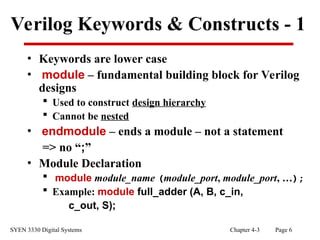
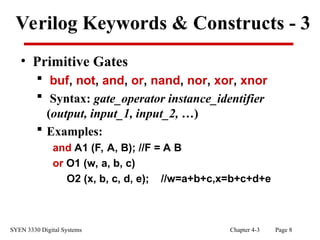
![SYEN 3330 Digital Systems Chapter 4-3 Page 7
Verilog Keywords & Constructs - 2
• Input Declaration
Scalar
• input list of input identifiers;
• Example: input A, B, c_in;
Vector
• input[range] list of input identifiers;
• Example: input[15:0] A, B, data;
• Output Declaration
Scalar Example: output c_out, OV, MINUS;
Vector Example: output[7:0] ACC, REG_IN,
data_out;](https://image.slidesharecdn.com/lecture4-3-240924030348-47761326/85/Lecture_4-3-ppt-on-verilog-hdl-7-320.jpg)
![SYEN 3330 Digital Systems Chapter 4-3 Page 9
Verilog Operators - 1
• Bitwise Operators
~ NOT
& AND
| OR
^ XOR
^~ or ~^ XNOR
• Example: input[3:0] A, B;
output[3:0] Z ;
assign Z = A | ~B;](https://image.slidesharecdn.com/lecture4-3-240924030348-47761326/85/Lecture_4-3-ppt-on-verilog-hdl-9-320.jpg)
![SYEN 3330 Digital Systems Chapter 4-3 Page 10
Verilog Operators - 2
• Arithmetic Operators
+, -, (plus others)
• Logical & Relational Operators
!, &&, | |, = =, !=, >=, <=, >, < (plus others)
• Concatenation & Replication Operators
{identifier_1, identifier_2, …}
{n{identifier}}
Examples: {REG_IN[6:0],Serial_in},
{8 {1’b0}}](https://image.slidesharecdn.com/lecture4-3-240924030348-47761326/85/Lecture_4-3-ppt-on-verilog-hdl-10-320.jpg)
![SYEN 3330 Digital Systems Chapter 4-3 Page 12
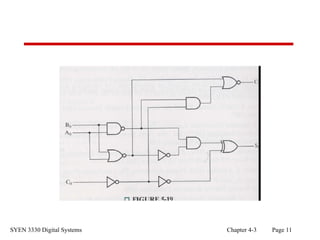
Structural Verilog
• Circuits can be described by a netlist as a text alternative to
a diagram - Example (See Figure 5-19 in text):
module fig519s (A0, B0, C0, C1, S0);
input A0, B0, C0;
output C1, S0;
//Seven internal wires needed
wire[1:7] N;
//Ports on primitive gates listed output port first
not G1 (N[3],C0), G2 (N[5],N[2]), G3 (N[6],N[3]);
nand G4 (N[1],A0,B0);
nor G5 (N[2],A0,B0), G6 (C1,N[2],N[4]);
and G7 (N[4],N[1],N[3]), G8 (N[7],N[1],N[5]);
xor G9 (S0,N[6],N[7]);
endmodule](https://image.slidesharecdn.com/lecture4-3-240924030348-47761326/85/Lecture_4-3-ppt-on-verilog-hdl-12-320.jpg)
![SYEN 3330 Digital Systems Chapter 4-3 Page 13
Dataflow Verilog - 1
• Circuit function can be described by assign statements
using Boolean equations (See Figure 5-19 in text):
module fig519d (A0, B0, C0, C1, S0);
input A0, B0, C0;
output C1, S0;
wire[1:2] N;
assign N[1] = ~(A0 & B0); /*Note: Cannot write ~& for
NAND */
assign N[2] = ~(A0 | B0);
assign C1 = ~((N[1] & ~C0) | N[2]);
assign S0 = (~N[2] & N[1])^(~(~C0));
endmodule](https://image.slidesharecdn.com/lecture4-3-240924030348-47761326/85/Lecture_4-3-ppt-on-verilog-hdl-13-320.jpg)
![SYEN 3330 Digital Systems Chapter 4-3 Page 14
Dataflow Verilog - 2
• Circuit function can be described by assign statements using the conditional
operator with binary combinations as in a truth table (See Figure 4-10 in
text):
module fig410dm (A, E_n, D_n);
input[1:0] A;
input E_n;
output[3:0] D_n;
//Conditional: (X) ? Y: Z - if X is true, then Y,else Z
assign D_n = {4{E_n}}&(
(A == 2'b00) ? 4'b1110:
(A == 2'b01) ? 4'b1101:
(A == 2'b10) ? 4'b1011:
(A == 2'b11) ? 4'b0111:
4'bxxxx);
endmodule](https://image.slidesharecdn.com/lecture4-3-240924030348-47761326/85/Lecture_4-3-ppt-on-verilog-hdl-14-320.jpg)
![SYEN 3330 Digital Systems Chapter 4-3 Page 15
Dataflow Verilog - 3
• Circuit function can be described by assign statements using
the conditional operator for binary decisions on inputs(See
Figure 4-10 in text):
module fig410dc (A, E_n, D_n);
input[1:0] A;
input E_n;
output[3:0] D_n;
/* Conditional: (X) ? Y: Z - if X is true, then Y,else Z */
assign D_n = {4{E_n}} & (A[1] ? (A[0] ? 4'h7 : 4'hB): (A[0] ?
4'hD : 4'hE));
endmodule](https://image.slidesharecdn.com/lecture4-3-240924030348-47761326/85/Lecture_4-3-ppt-on-verilog-hdl-15-320.jpg)
![SYEN 3330 Digital Systems Chapter 4-3 Page 16
Behavioral & Hierarchical Verilog
• Circuit function can be described by assign statements at
higher than the logic level (See Figure 5-8 in text):
module addsub (A, B, R, sub) ;
input [3:0] A, B ;
output [3:0] R ;//See Fig. 5-18 for carry out
input sub ;
wire [3:0] data_out;
add A1 (A, data_out, sub, R);
M1comp C1 (B, data_out, sub);
endmodule](https://image.slidesharecdn.com/lecture4-3-240924030348-47761326/85/Lecture_4-3-ppt-on-verilog-hdl-16-320.jpg)
![SYEN 3330 Digital Systems Chapter 4-3 Page 17
Behavioral & Hierarchical Verilog
module add (X, Y, C_in, S);
input [3:0] X, Y;
input C_in;
output [3:0] S;
assign S = X + Y + {3'b0, C_in};
endmodule
module M1comp (data_in, data_out, comp);
input[3:0] data_in;
input comp;
output [3:0] data_out;
assign data_out = {4{comp}} ^ data_in;
endmodule](https://image.slidesharecdn.com/lecture4-3-240924030348-47761326/85/Lecture_4-3-ppt-on-verilog-hdl-17-320.jpg)