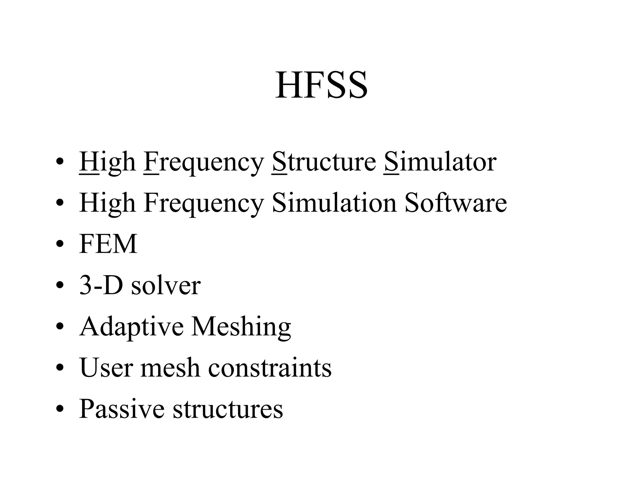
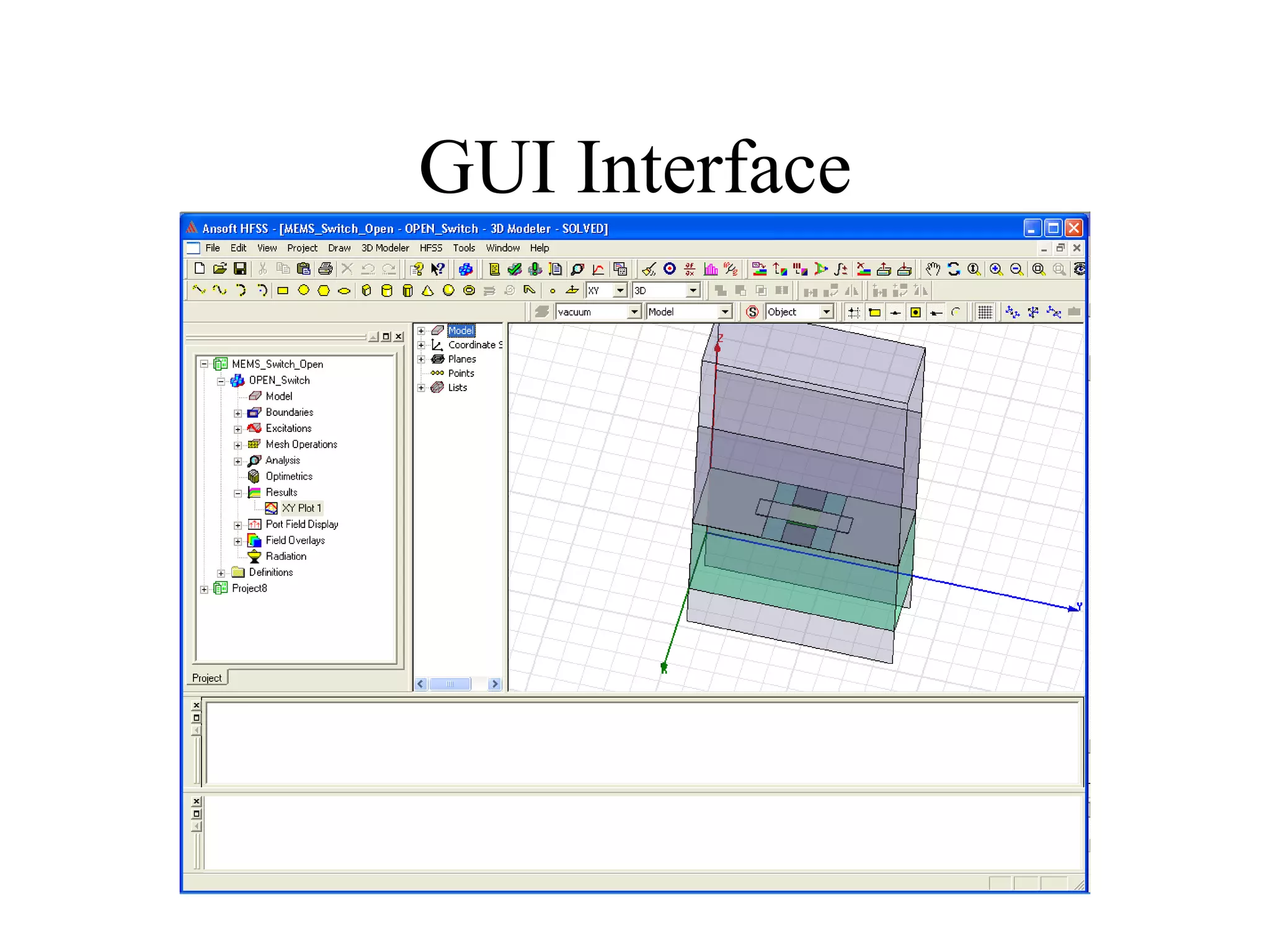
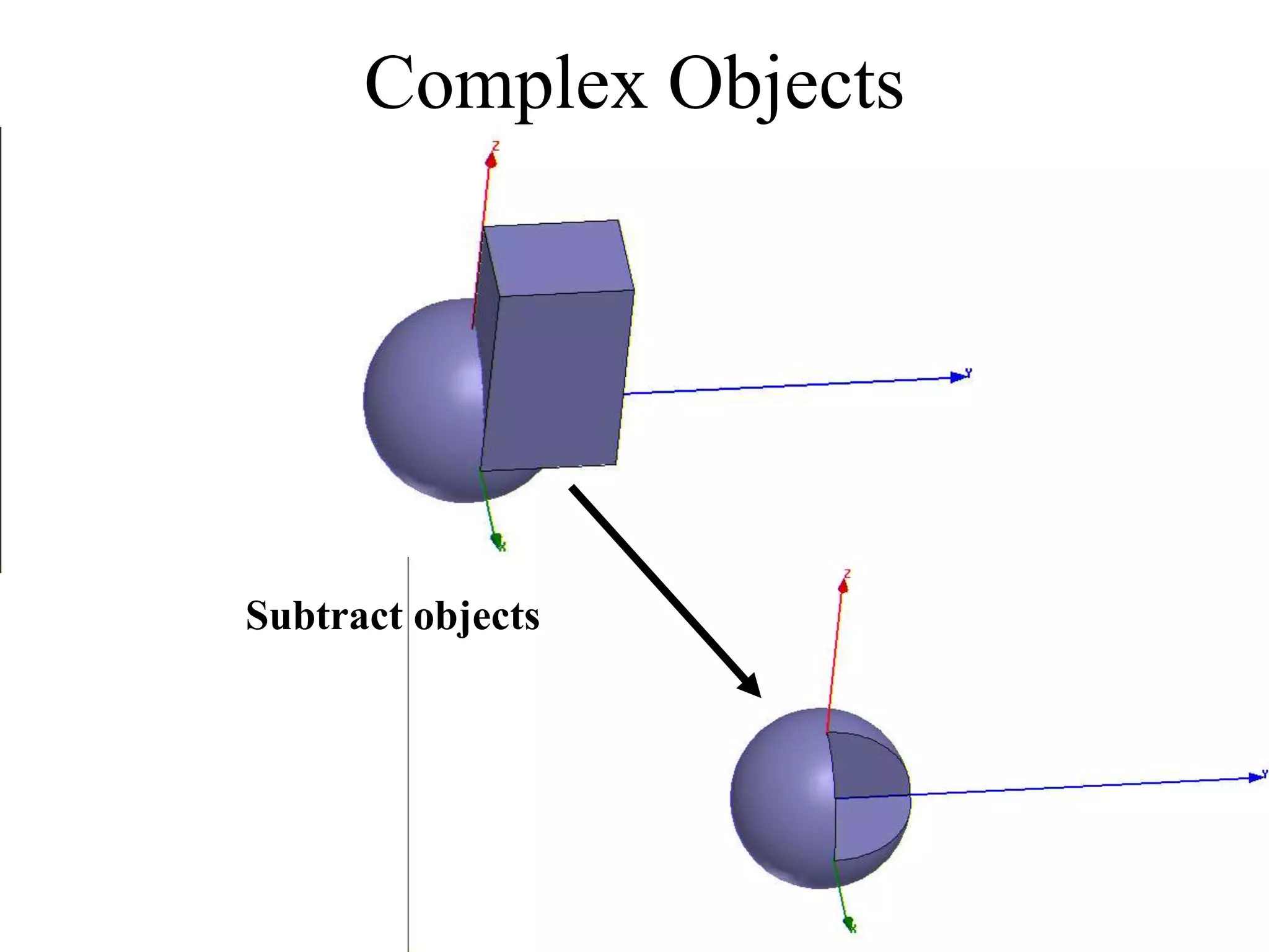
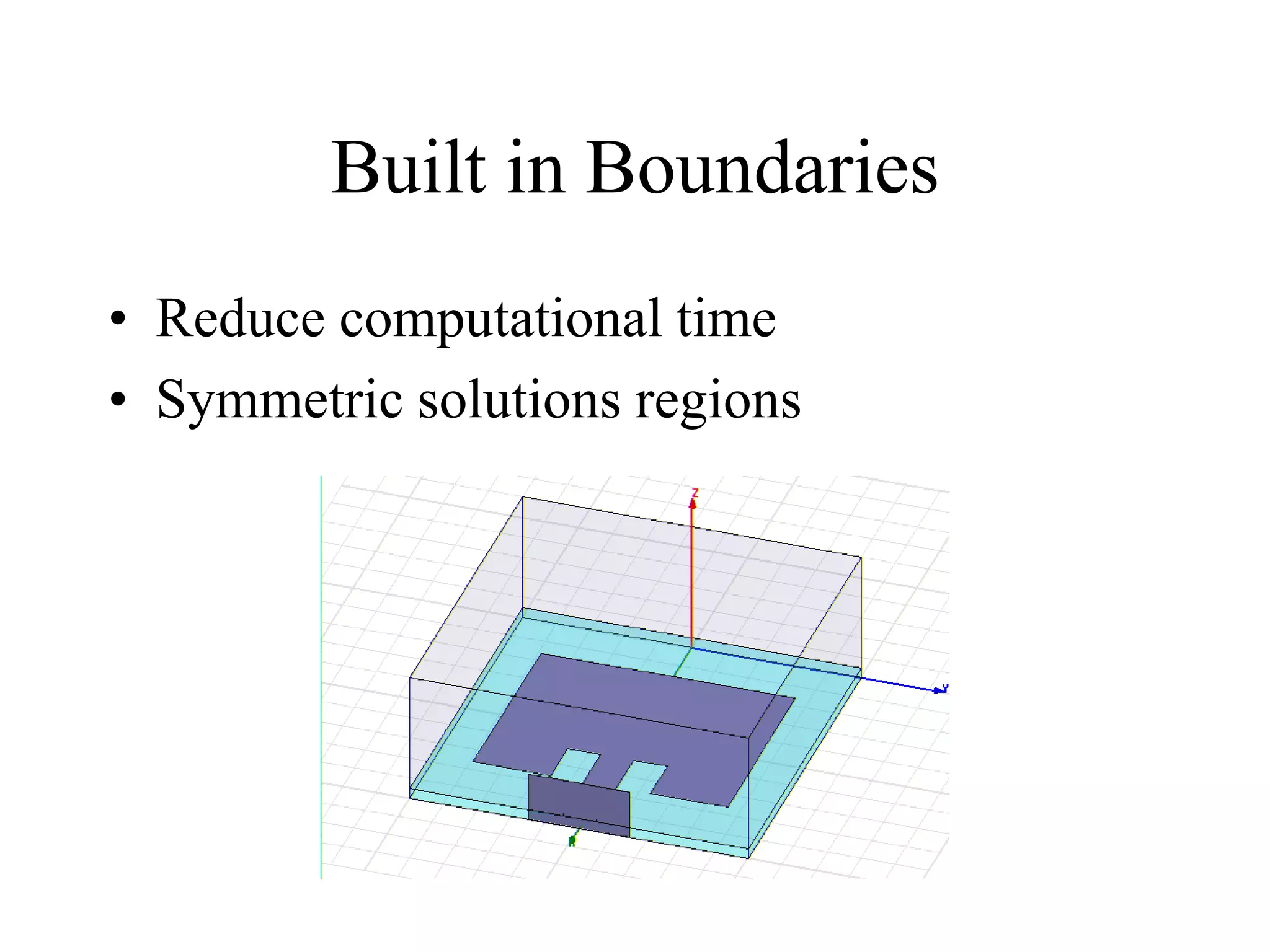
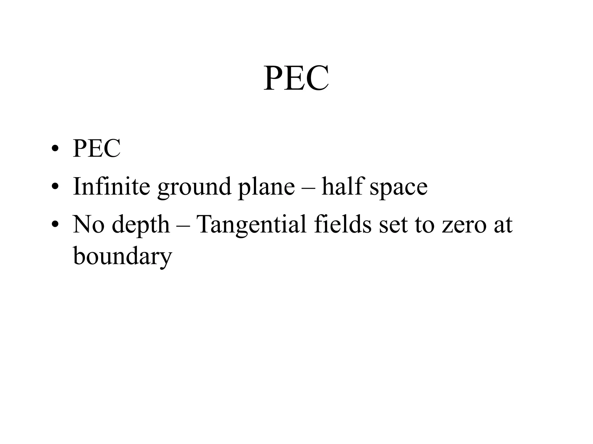
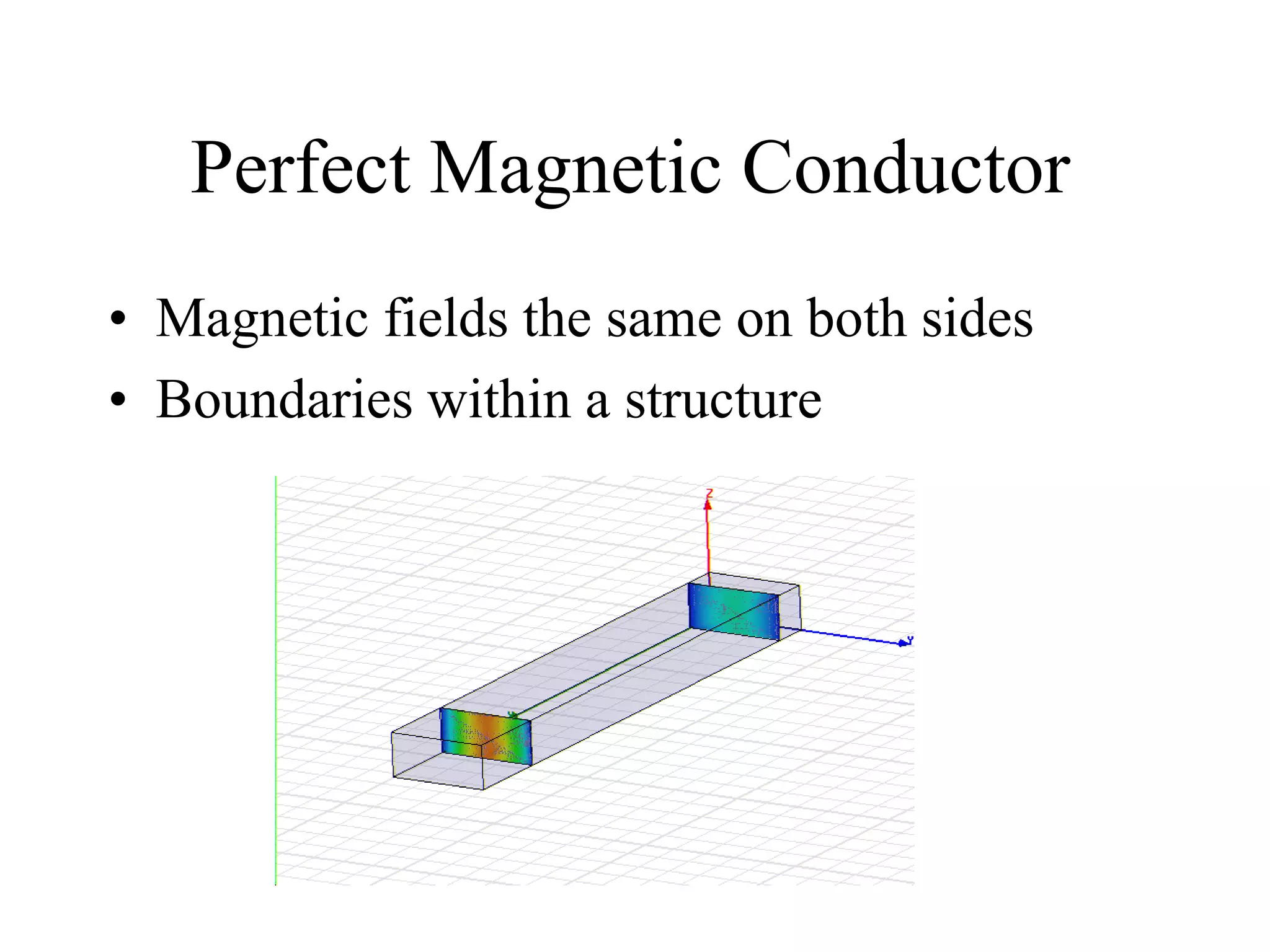
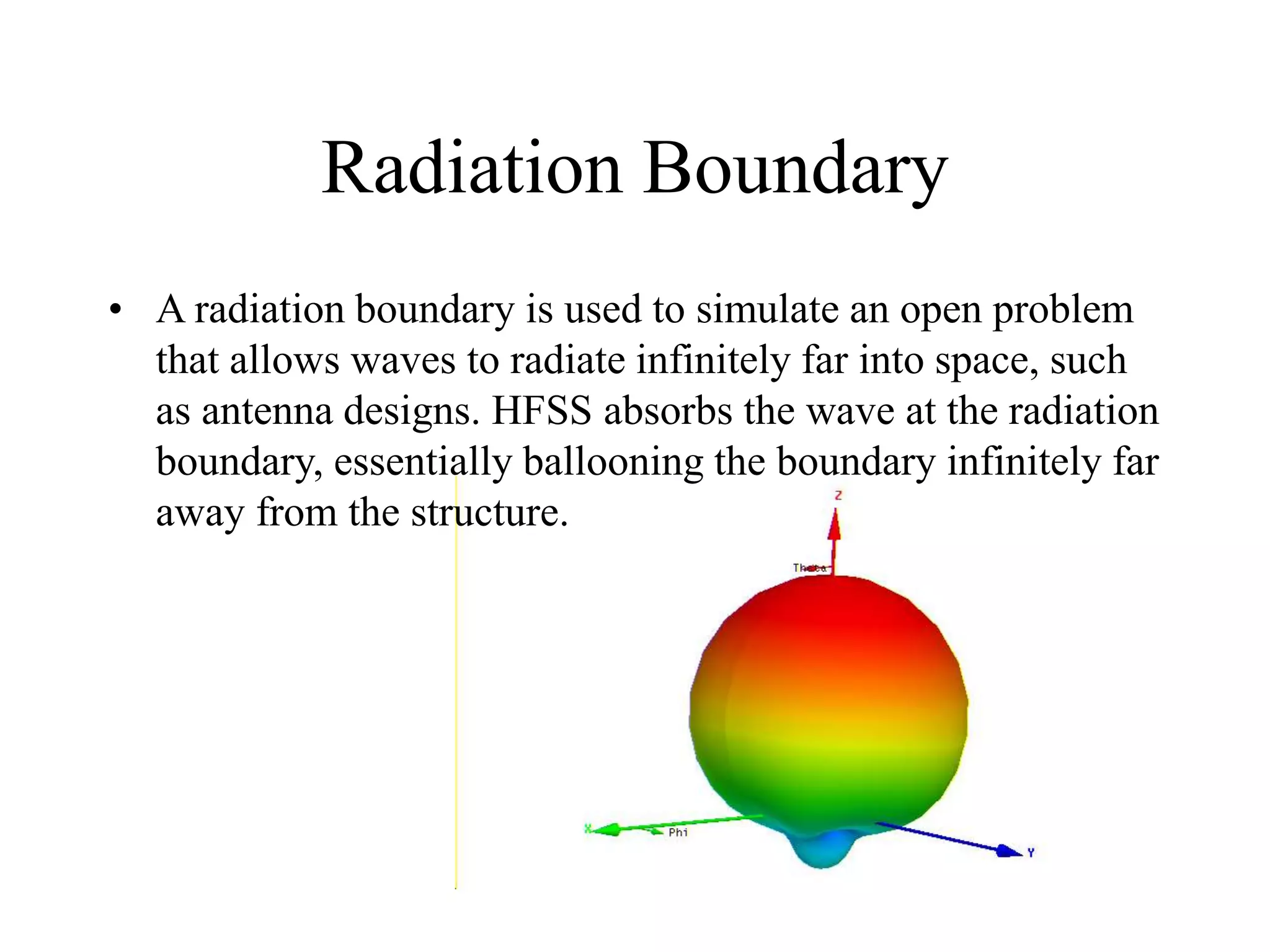
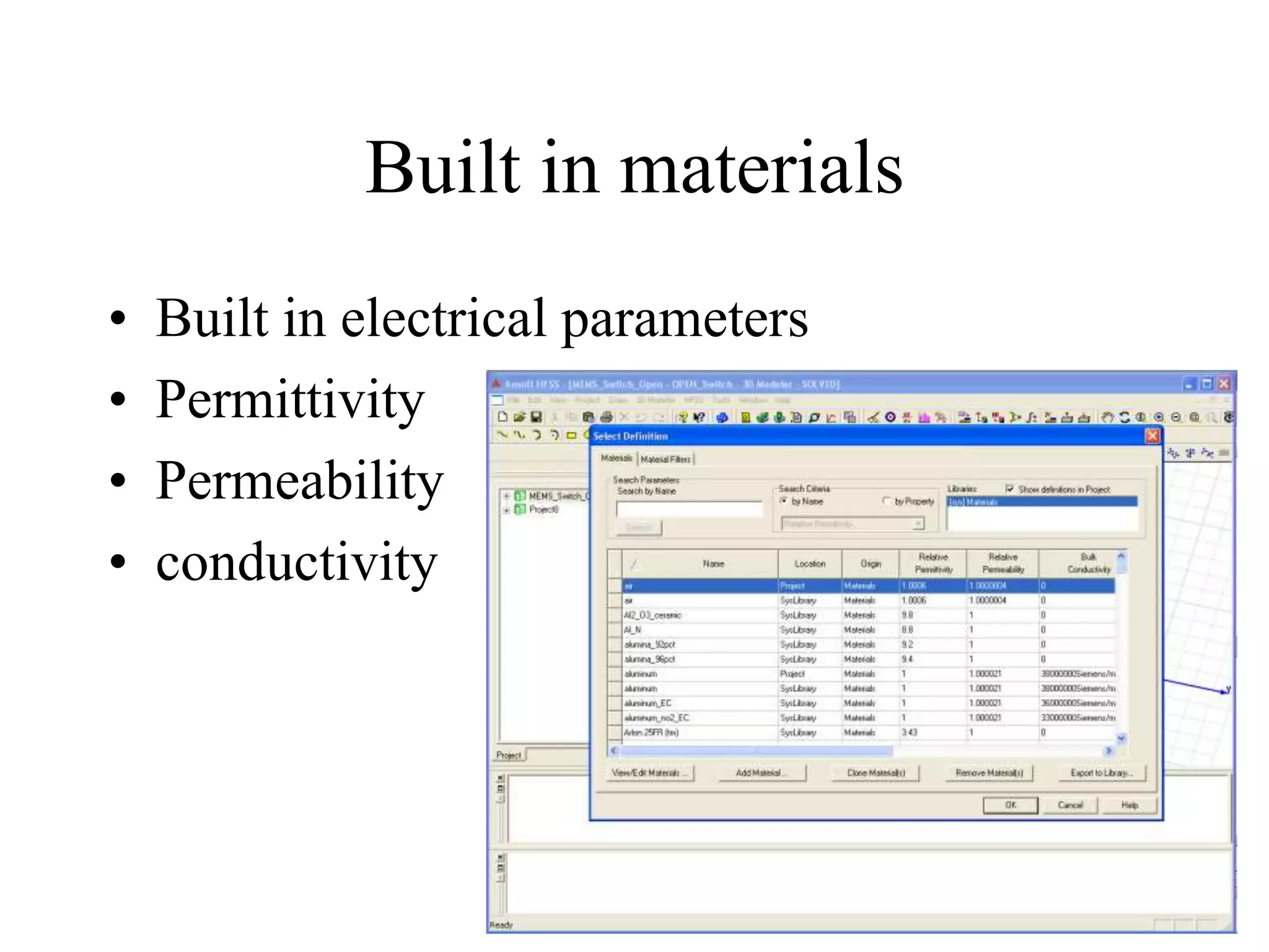
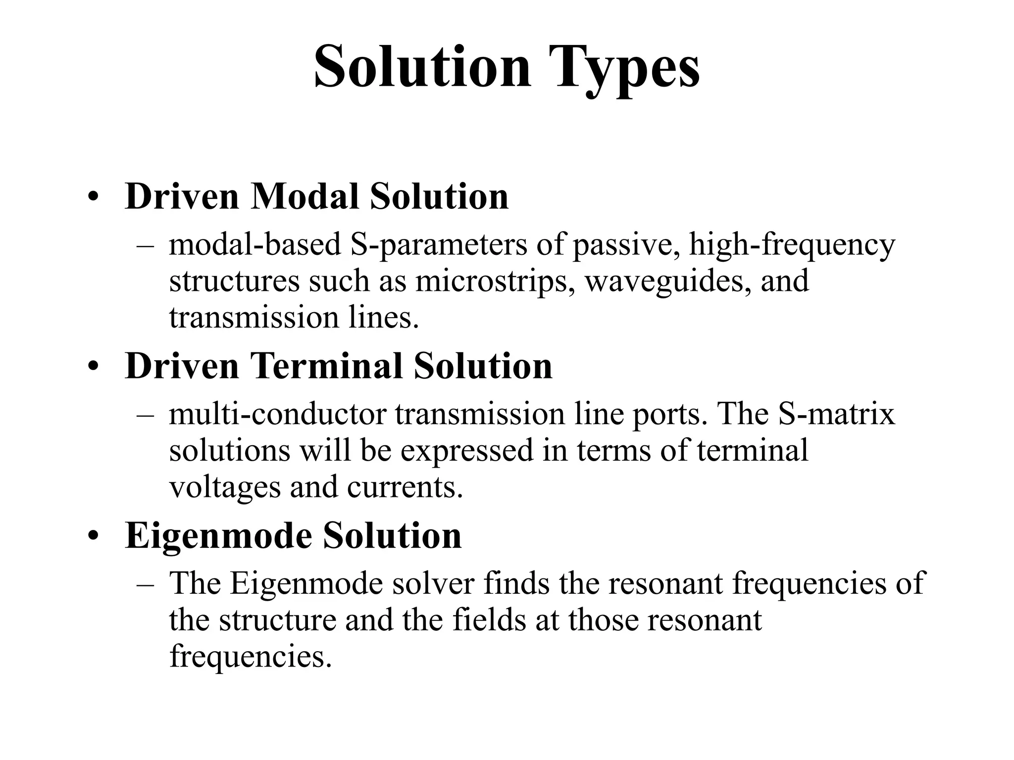
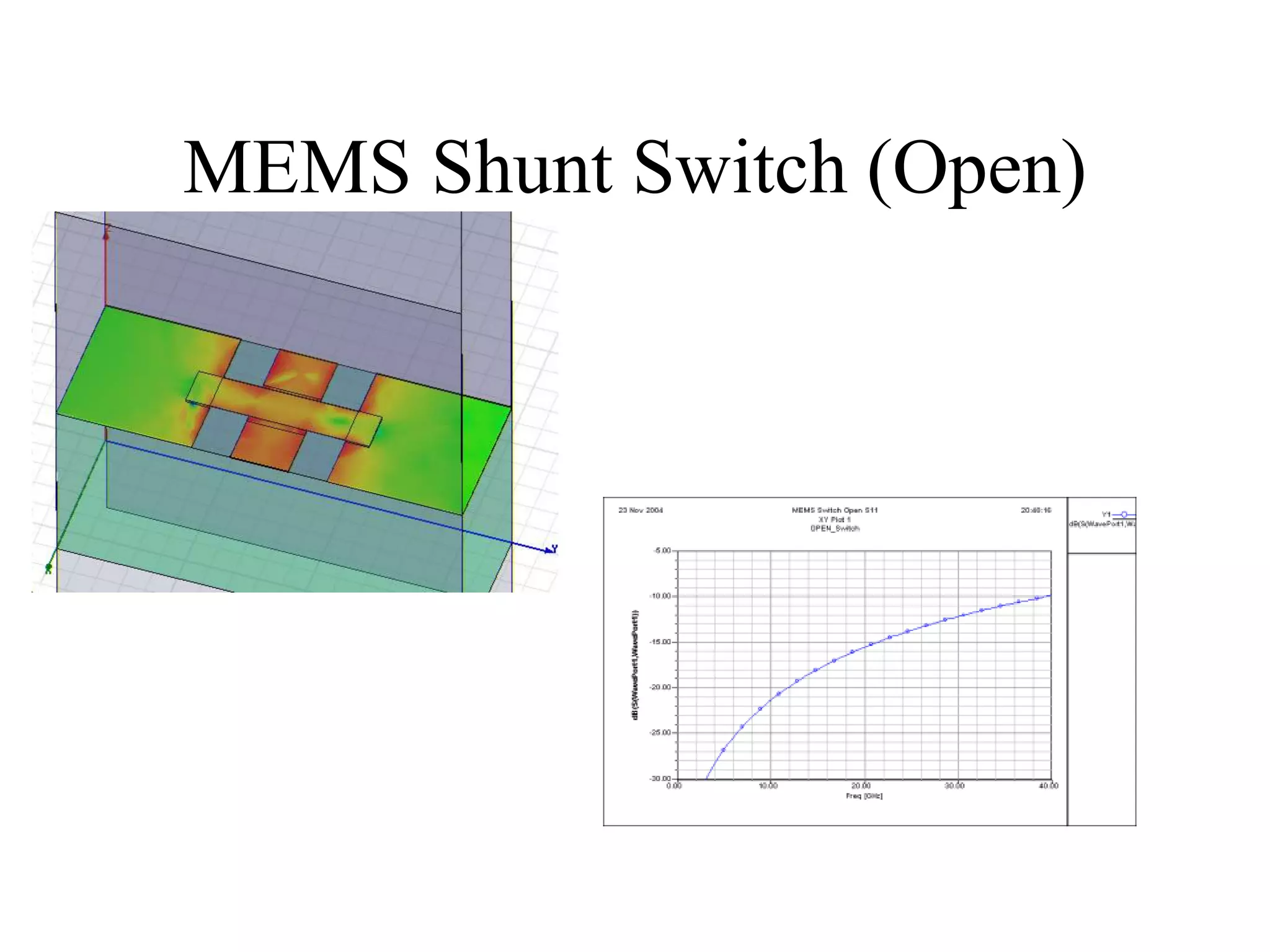
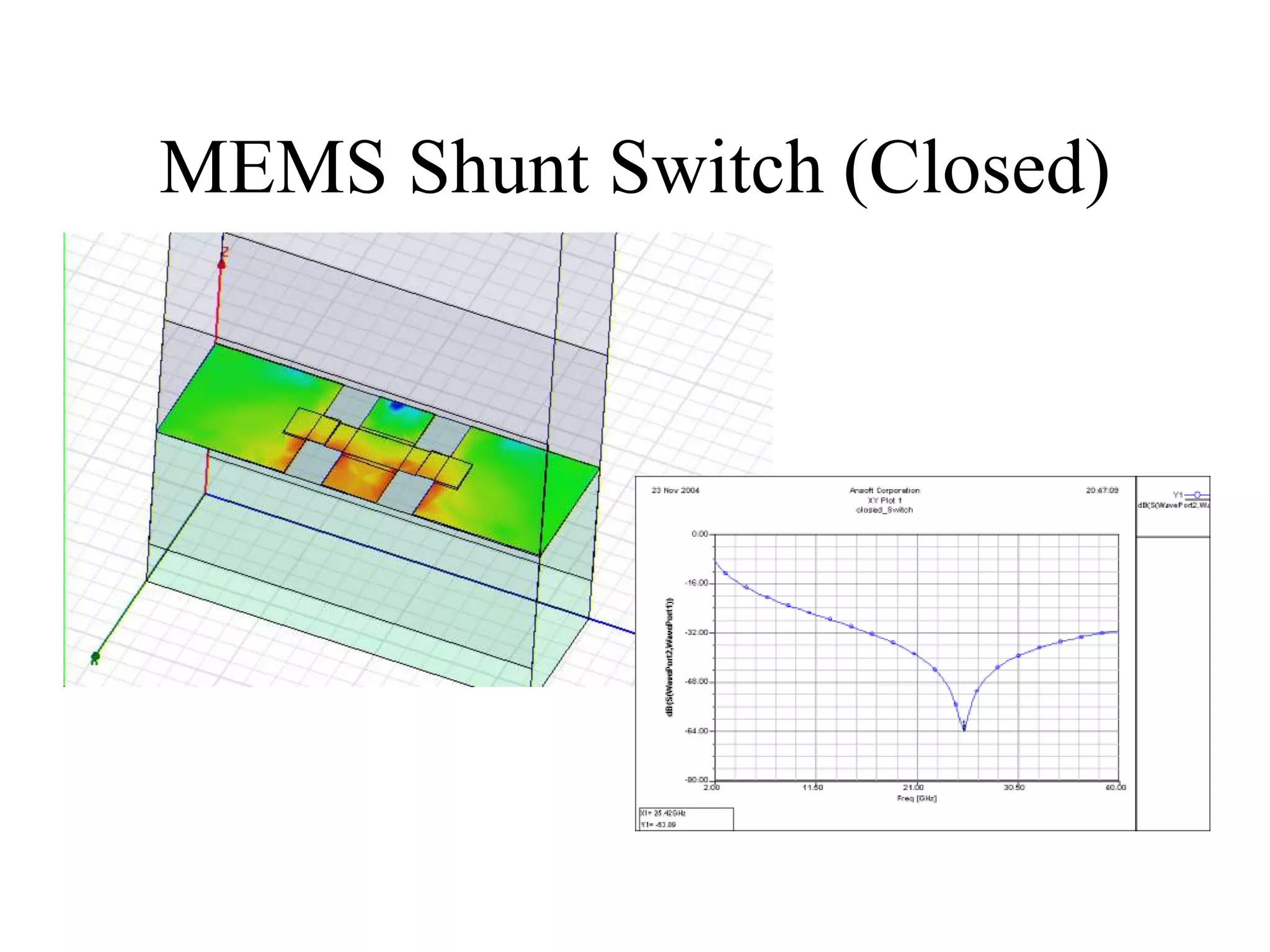
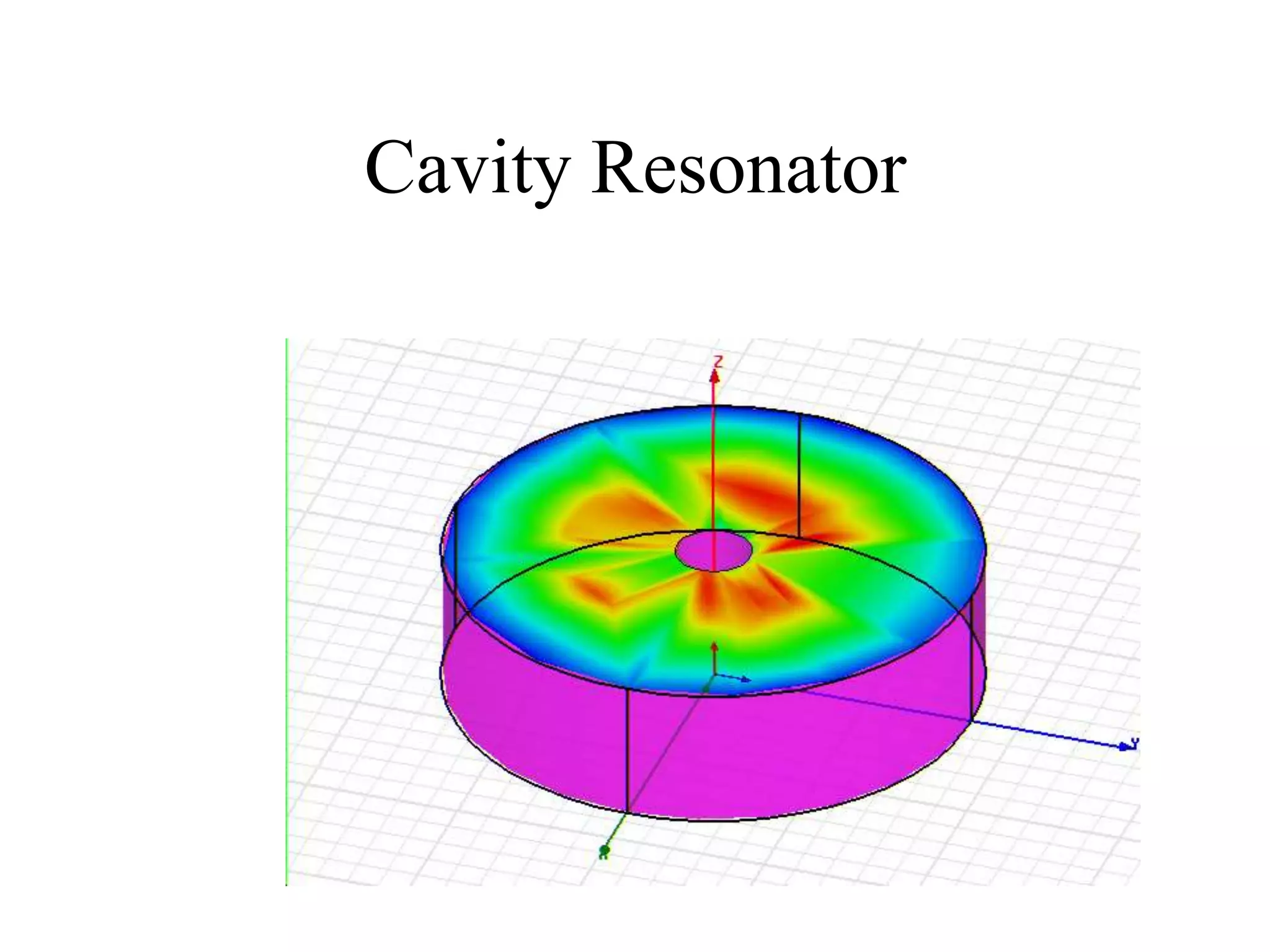
Alex Bates
Fall 2004
ECE 563 – Computational
Electromagnetics
HFSS
HFSS
• High Frequency Structure Simulator
• High Frequency Simulation Software
• FEM
• 3-D solver
• Adaptive Meshing
• User mesh constraints
• Passive structures
GUI Interface
Complex Objects
Subtract objects
Built in Boundaries
• Reduce computational time
• Symmetric solutions regions
PEC
• PEC
• Infinite ground plane – half space
• No depth – Tangential fields set to zero at
boundary
Perfect Magnetic Conductor
• Magnetic fields the same on both sides
• Boundaries within a structure
Radiation Boundary
• A radiation boundary is used to simulate an open problem
that allows waves to radiate infinitely far into space, such
as antenna designs. HFSS absorbs the wave at the radiation
boundary, essentially ballooning the boundary infinitely far
away from the structure.
Other boundaries
• PML
• Impedance (resistive surface)
• Finite conductivity
• Symmetry
Built in materials
• Built in electrical parameters
• Permittivity
• Permeability
• conductivity
Length Based Mesh Refinements
• Instruct HFSS to refine the length of
tetrahedral elements until they are below a
specified value
• Number of elements can be restricted
• Portions of the problem space can be
selected for refinement
• Surface objects and volumetric regions
Skin Depth Based Mesh
Refinements
• Depth of tetrahedral set to skin depth for the
solution frequency
• Depth of tetrahedral layers can be limited
for highly conductive boundaries
Surface Mesh
Solution Types
• Driven Modal Solution
– modal-based S-parameters of passive, high-frequency
structures such as microstrips, waveguides, and
transmission lines.
• Driven Terminal Solution
– multi-conductor transmission line ports. The S-matrix
solutions will be expressed in terms of terminal
voltages and currents.
• Eigenmode Solution
– The Eigenmode solver finds the resonant frequencies of
the structure and the fields at those resonant
frequencies.
Post Processing Analysis
• Parametric
– Solve for a series of values and compare
• Optimization of variables
– set goal functions HFSS will optimize
• Tuning post optimization interactively
• Sensitivity
– Optimizer perturbs variables to explore how
each changes the solution
Patch Antenna
Couplers
Port 1
(lower)
Port 2
(lower)
Port 3
(upper)
Port 4
(upper)
Microstrip Equal-Ripple LPF
MEMS Shunt Switch (Open)
MEMS Shunt Switch (Closed)
Cavity Resonator

Lecture24.ppt

  • 1.
    Alex Bates Fall 2004 ECE563 – Computational Electromagnetics HFSS
  • 2.
    HFSS • High FrequencyStructure Simulator • High Frequency Simulation Software • FEM • 3-D solver • Adaptive Meshing • User mesh constraints • Passive structures
  • 3.
  • 4.
  • 5.
    Built in Boundaries •Reduce computational time • Symmetric solutions regions
  • 6.
    PEC • PEC • Infiniteground plane – half space • No depth – Tangential fields set to zero at boundary
  • 7.
    Perfect Magnetic Conductor •Magnetic fields the same on both sides • Boundaries within a structure
  • 8.
    Radiation Boundary • Aradiation boundary is used to simulate an open problem that allows waves to radiate infinitely far into space, such as antenna designs. HFSS absorbs the wave at the radiation boundary, essentially ballooning the boundary infinitely far away from the structure.
  • 9.
    Other boundaries • PML •Impedance (resistive surface) • Finite conductivity • Symmetry
  • 10.
    Built in materials •Built in electrical parameters • Permittivity • Permeability • conductivity
  • 11.
    Length Based MeshRefinements • Instruct HFSS to refine the length of tetrahedral elements until they are below a specified value • Number of elements can be restricted • Portions of the problem space can be selected for refinement • Surface objects and volumetric regions
  • 12.
    Skin Depth BasedMesh Refinements • Depth of tetrahedral set to skin depth for the solution frequency • Depth of tetrahedral layers can be limited for highly conductive boundaries
  • 13.
  • 15.
    Solution Types • DrivenModal Solution – modal-based S-parameters of passive, high-frequency structures such as microstrips, waveguides, and transmission lines. • Driven Terminal Solution – multi-conductor transmission line ports. The S-matrix solutions will be expressed in terms of terminal voltages and currents. • Eigenmode Solution – The Eigenmode solver finds the resonant frequencies of the structure and the fields at those resonant frequencies.
  • 16.
    Post Processing Analysis •Parametric – Solve for a series of values and compare • Optimization of variables – set goal functions HFSS will optimize • Tuning post optimization interactively • Sensitivity – Optimizer perturbs variables to explore how each changes the solution
  • 17.
  • 18.
  • 19.
  • 20.
  • 21.
  • 22.