DBMS (Database Management System) is software that stores, organizes, and manages data efficiently. It allows users to create, read, update, and delete data while ensuring security, integrity, and consistency.
Key Points:
Slide 3- 2
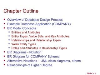
ChapterOutline
Overview of Database Design Process
Example Database Application (COMPANY)
ER Model Concepts
Entities and Attributes
Entity Types, Value Sets, and Key Attributes
Relationships and Relationship Types
Weak Entity Types
Roles and Attributes in Relationship Types
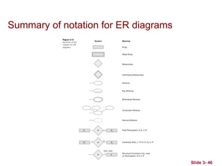
ER Diagrams - Notation
ER Diagram for COMPANY Schema
Alternative Notations – UML class diagrams, others
Relationships of Higher Degree
3.
Slide 3- 3
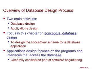
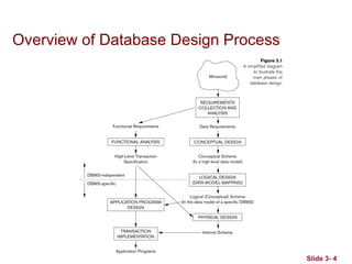
Overviewof Database Design Process
Two main activities:
Database design
Applications design
Focus in this chapter on conceptual database
design
To design the conceptual schema for a database
application
Applications design focuses on the programs and
interfaces that access the database
Generally considered part of software engineering
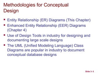
Methodologies for Conceptual
Design
Entity Relationship (ER) Diagrams (This Chapter)
Enhanced Entity Relationship (EER) Diagrams
(Chapter 4)
Use of Design Tools in industry for designing and
documenting large scale designs
The UML (Unified Modeling Language) Class
Diagrams are popular in industry to document
conceptual database designs
Slide 3- 5
6.
Slide 3- 6
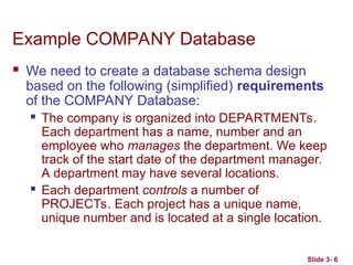
ExampleCOMPANY Database
We need to create a database schema design
based on the following (simplified) requirements
of the COMPANY Database:
The company is organized into DEPARTMENTs.
Each department has a name, number and an
employee who manages the department. We keep
track of the start date of the department manager.
A department may have several locations.
Each department controls a number of
PROJECTs. Each project has a unique name,
unique number and is located at a single location.
7.
Slide 3- 7
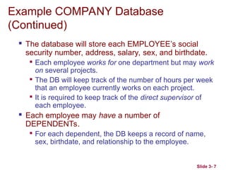
ExampleCOMPANY Database
(Continued)
The database will store each EMPLOYEE’s social
security number, address, salary, sex, and birthdate.
Each employee works for one department but may work
on several projects.
The DB will keep track of the number of hours per week
that an employee currently works on each project.
It is required to keep track of the direct supervisor of
each employee.
Each employee may have a number of
DEPENDENTs.
For each dependent, the DB keeps a record of name,
sex, birthdate, and relationship to the employee.
8.
Slide 3- 8
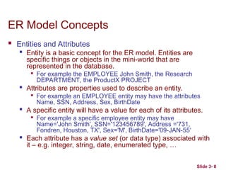
ERModel Concepts
Entities and Attributes
Entity is a basic concept for the ER model. Entities are
specific things or objects in the mini-world that are
represented in the database.
For example the EMPLOYEE John Smith, the Research
DEPARTMENT, the ProductX PROJECT
Attributes are properties used to describe an entity.
For example an EMPLOYEE entity may have the attributes
Name, SSN, Address, Sex, BirthDate
A specific entity will have a value for each of its attributes.
For example a specific employee entity may have
Name='John Smith', SSN='123456789', Address ='731,
Fondren, Houston, TX', Sex='M', BirthDate='09-JAN-55‘
Each attribute has a value set (or data type) associated with
it – e.g. integer, string, date, enumerated type, …
9.
Slide 3- 9
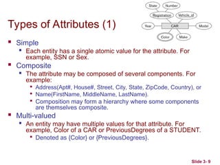
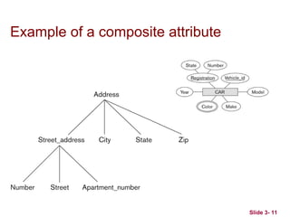
Typesof Attributes (1)
Simple
Each entity has a single atomic value for the attribute. For
example, SSN or Sex.
Composite
The attribute may be composed of several components. For
example:
Address(Apt#, House#, Street, City, State, ZipCode, Country), or
Name(FirstName, MiddleName, LastName).
Composition may form a hierarchy where some components
are themselves composite.
Multi-valued
An entity may have multiple values for that attribute. For
example, Color of a CAR or PreviousDegrees of a STUDENT.
Denoted as {Color} or {PreviousDegrees}.
10.
Slide 3- 10
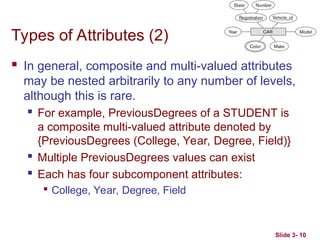
Typesof Attributes (2)
In general, composite and multi-valued attributes
may be nested arbitrarily to any number of levels,
although this is rare.
For example, PreviousDegrees of a STUDENT is
a composite multi-valued attribute denoted by
{PreviousDegrees (College, Year, Degree, Field)}
Multiple PreviousDegrees values can exist
Each has four subcomponent attributes:
College, Year, Degree, Field
Slide 3- 12
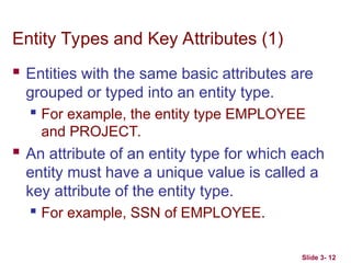
EntityTypes and Key Attributes (1)
Entities with the same basic attributes are
grouped or typed into an entity type.
For example, the entity type EMPLOYEE
and PROJECT.
An attribute of an entity type for which each
entity must have a unique value is called a
key attribute of the entity type.
For example, SSN of EMPLOYEE.
13.
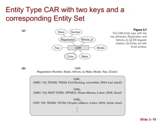
Slide 3- 13
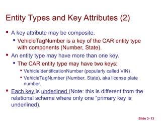
EntityTypes and Key Attributes (2)
A key attribute may be composite.
VehicleTagNumber is a key of the CAR entity type
with components (Number, State).
An entity type may have more than one key.
The CAR entity type may have two keys:
VehicleIdentificationNumber (popularly called VIN)
VehicleTagNumber (Number, State), aka license plate
number.
Each key is underlined (Note: this is different from the
relational schema where only one “primary key is
underlined).
14.
Slide 3- 14
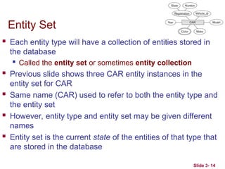
EntitySet
Each entity type will have a collection of entities stored in
the database
Called the entity set or sometimes entity collection
Previous slide shows three CAR entity instances in the
entity set for CAR
Same name (CAR) used to refer to both the entity type and
the entity set
However, entity type and entity set may be given different
names
Entity set is the current state of the entities of that type that
are stored in the database
15.
Value Sets (Domains)of Attributes
Each simple attribute is associated with a value
set
E.g., Lastname has a value which is a character
string of upto 15 characters, say
Date has a value consisting of MM-DD-YYYY
where each letter is an integer
A value set specifies the set of values associated
with an attribute
Slide 3- 15
16.
Slide 3- 17
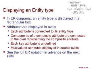
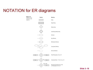
Displayingan Entity type
In ER diagrams, an entity type is displayed in a
rectangular box
Attributes are displayed in ovals
Each attribute is connected to its entity type
Components of a composite attribute are connected
to the oval representing the composite attribute
Each key attribute is underlined
Multivalued attributes displayed in double ovals
See the full ER notation in advance on the next
slide
Slide 3- 20
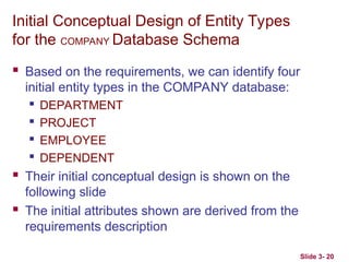
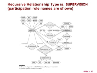
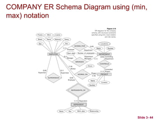
InitialConceptual Design of Entity Types
for the COMPANY Database Schema
Based on the requirements, we can identify four
initial entity types in the COMPANY database:
DEPARTMENT
PROJECT
EMPLOYEE
DEPENDENT
Their initial conceptual design is shown on the
following slide
The initial attributes shown are derived from the
requirements description
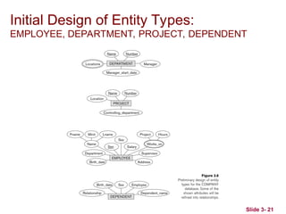
Slide 3- 22
Refiningthe initial design by introducing
relationships
The initial design is typically not complete
Some aspects in the requirements will be
represented as relationships
ER model has three main concepts:
Entities (and their entity types and entity sets)
Attributes (simple, composite, multivalued)
Relationships (and their relationship types and
relationship sets)
We introduce relationship concepts next
22.
Slide 3- 23
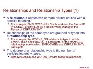
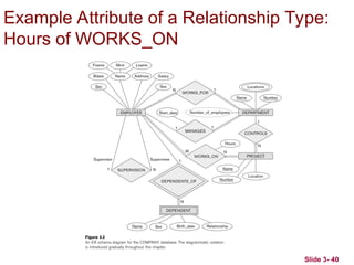
Relationshipsand Relationship Types (1)
A relationship relates two or more distinct entities with a
specific meaning.
For example, EMPLOYEE John Smith works on the ProductX
PROJECT, or EMPLOYEE Franklin Wong manages the
Research DEPARTMENT.
Relationships of the same type are grouped or typed into
a relationship type.
For example, the WORKS_ON relationship type in which
EMPLOYEEs and PROJECTs participate, or the MANAGES
relationship type in which EMPLOYEEs and DEPARTMENTs
participate.
The degree of a relationship type is the number of
participating entity types.
Both MANAGES and WORKS_ON are binary relationships.
23.
Slide 3- 24
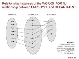
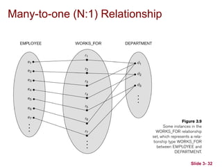
Relationshipinstances of the WORKS_FOR N:1
relationship between EMPLOYEE and DEPARTMENT
Slide 3- 26
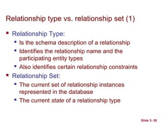
Relationshiptype vs. relationship set (1)
Relationship Type:
Is the schema description of a relationship
Identifies the relationship name and the
participating entity types
Also identifies certain relationship constraints
Relationship Set:
The current set of relationship instances
represented in the database
The current state of a relationship type
26.
Slide 3- 27
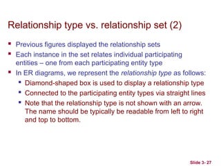
Relationshiptype vs. relationship set (2)
Previous figures displayed the relationship sets
Each instance in the set relates individual participating
entities – one from each participating entity type
In ER diagrams, we represent the relationship type as follows:
Diamond-shaped box is used to display a relationship type
Connected to the participating entity types via straight lines
Note that the relationship type is not shown with an arrow.
The name should be typically be readable from left to right
and top to bottom.
27.
Slide 3- 28
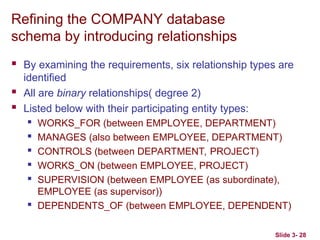
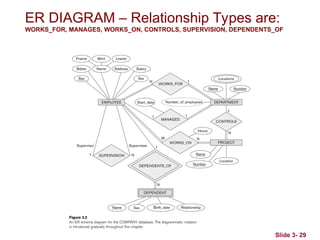
Refiningthe COMPANY database
schema by introducing relationships
By examining the requirements, six relationship types are
identified
All are binary relationships( degree 2)
Listed below with their participating entity types:
WORKS_FOR (between EMPLOYEE, DEPARTMENT)
MANAGES (also between EMPLOYEE, DEPARTMENT)
CONTROLS (between DEPARTMENT, PROJECT)
WORKS_ON (between EMPLOYEE, PROJECT)
SUPERVISION (between EMPLOYEE (as subordinate),
EMPLOYEE (as supervisor))
DEPENDENTS_OF (between EMPLOYEE, DEPENDENT)
Slide 3- 30
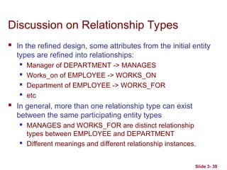
Discussionon Relationship Types
In the refined design, some attributes from the initial entity
types are refined into relationships:
Manager of DEPARTMENT -> MANAGES
Works_on of EMPLOYEE -> WORKS_ON
Department of EMPLOYEE -> WORKS_FOR
etc
In general, more than one relationship type can exist
between the same participating entity types
MANAGES and WORKS_FOR are distinct relationship
types between EMPLOYEE and DEPARTMENT
Different meanings and different relationship instances.
30.
Slide 3- 31
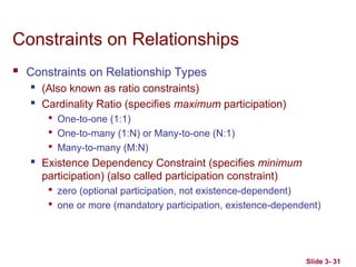
Constraintson Relationships
Constraints on Relationship Types
(Also known as ratio constraints)
Cardinality Ratio (specifies maximum participation)
One-to-one (1:1)
One-to-many (1:N) or Many-to-one (N:1)
Many-to-many (M:N)
Existence Dependency Constraint (specifies minimum
participation) (also called participation constraint)
zero (optional participation, not existence-dependent)
one or more (mandatory participation, existence-dependent)
Slide 3- 34
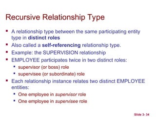
RecursiveRelationship Type
A relationship type between the same participating entity
type in distinct roles
Also called a self-referencing relationship type.
Example: the SUPERVISION relationship
EMPLOYEE participates twice in two distinct roles:
supervisor (or boss) role
supervisee (or subordinate) role
Each relationship instance relates two distinct EMPLOYEE
entities:
One employee in supervisor role
One employee in supervisee role
34.
Slide 3- 35
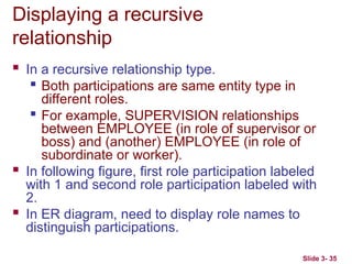
Displayinga recursive
relationship
In a recursive relationship type.
Both participations are same entity type in
different roles.
For example, SUPERVISION relationships
between EMPLOYEE (in role of supervisor or
boss) and (another) EMPLOYEE (in role of
subordinate or worker).
In following figure, first role participation labeled
with 1 and second role participation labeled with
2.
In ER diagram, need to display role names to
distinguish participations.
Slide 3- 37
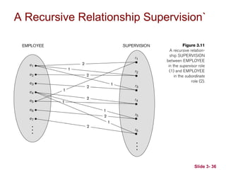
RecursiveRelationship Type is: SUPERVISION
(participation role names are shown)
37.
Slide 3- 38
WeakEntity Types
An entity that does not have a key attribute and that is identification-
dependent on another entity type.
A weak entity must participate in an identifying relationship type with an
owner or identifying entity type
Entities are identified by the combination of:
A partial key of the weak entity type
The particular entity they are related to in the identifying relationship
type
Example:
A DEPENDENT entity is identified by the dependent’s first name, and
the specific EMPLOYEE with whom the dependent is related
Name of DEPENDENT is the partial key
DEPENDENT is a weak entity type
EMPLOYEE is its identifying entity type via the identifying relationship
type DEPENDENT_OF
38.
Slide 3- 39
Attributesof Relationship types
A relationship type can have attributes:
For example, HoursPerWeek of WORKS_ON
Its value for each relationship instance describes
the number of hours per week that an EMPLOYEE
works on a PROJECT.
A value of HoursPerWeek depends on a particular
(employee, project) combination
Most relationship attributes are used with M:N
relationships
In 1:N relationships, they can be transferred to the
entity type on the N-side of the relationship
Slide 3- 41
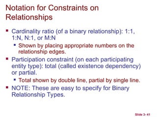
Notationfor Constraints on
Relationships
Cardinality ratio (of a binary relationship): 1:1,
1:N, N:1, or M:N
Shown by placing appropriate numbers on the
relationship edges.
Participation constraint (on each participating
entity type): total (called existence dependency)
or partial.
Total shown by double line, partial by single line.
NOTE: These are easy to specify for Binary
Relationship Types.
41.
Slide 3- 42
Alternative(min, max) notation for
relationship structural constraints:
Specified on each participation of an entity type E in a relationship
type R
Specifies that each entity e in E participates in at least min and at
most max relationship instances in R
Default (no constraint): min=0, max=n (signifying no limit)
Must have min max, min0, max 1
Derived from the knowledge of mini-world constraints
Examples:
A department has exactly one manager and an employee can
manage at most one department.
Specify (0,1) for participation of EMPLOYEE in MANAGES
Specify (1,1) for participation of DEPARTMENT in MANAGES
An employee can work for exactly one department, but a
department can have any number of employees.
Specify (1,1) for participation of EMPLOYEE in WORKS_FOR
Specify (0,n) for participation of DEPARTMENT in WORKS_FOR
42.
Slide 3- 43
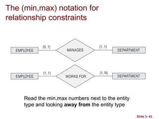
The(min,max) notation for
relationship constraints
Read the min,max numbers next to the entity
type and looking away from the entity type
Slide 3- 45
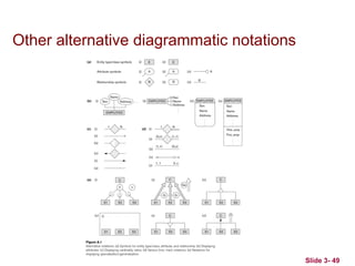
Alternativediagrammatic notation
ER diagrams is one popular example for
displaying database schemas
Many other notations exist in the literature and in
various database design and modeling tools
Appendix A illustrates some of the alternative
notations that have been used
UML class diagrams is representative of another
way of displaying ER concepts that is used in
several commercial design tools
Slide 3- 47
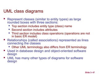
UMLclass diagrams
Represent classes (similar to entity types) as large
rounded boxes with three sections:
Top section includes entity type (class) name
Second section includes attributes
Third section includes class operations (operations are not
in basic ER model)
Relationships (called associations) represented as lines
connecting the classes
Other UML terminology also differs from ER terminology
Used in database design and object-oriented software
design
UML has many other types of diagrams for software
design
Slide 3- 50
Relationshipsof Higher Degree
Relationship types of degree 2 are called binary
Relationship types of degree 3 are called ternary
and of degree n are called n-ary
In general, an n-ary relationship is not equivalent
to n binary relationships
Constraints are harder to specify for higher-
degree relationships (n > 2) than for binary
relationships
50.
Slide 3- 51
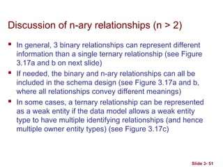
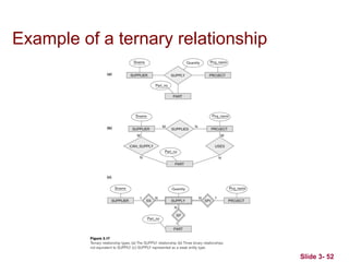
Discussionof n-ary relationships (n > 2)
In general, 3 binary relationships can represent different
information than a single ternary relationship (see Figure
3.17a and b on next slide)
If needed, the binary and n-ary relationships can all be
included in the schema design (see Figure 3.17a and b,
where all relationships convey different meanings)
In some cases, a ternary relationship can be represented
as a weak entity if the data model allows a weak entity
type to have multiple identifying relationships (and hence
multiple owner entity types) (see Figure 3.17c)
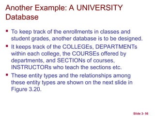
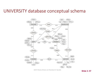
Another Example: AUNIVERSITY
Database
To keep track of the enrollments in classes and
student grades, another database is to be designed.
It keeps track of the COLLEGEs, DEPARTMENTs
within each college, the COURSEs offered by
departments, and SECTIONs of courses,
INSTRUCTORs who teach the sections etc.
These entity types and the relationships among
these entity types are shown on the next slide in
Figure 3.20.
Slide 3- 56
Slide 3- 61
ChapterSummary
ER Model Concepts: Entities, attributes,
relationships
Constraints in the ER model
Using ER in step-by-step mode conceptual schema
design for the COMPANY database
ER Diagrams - Notation
Alternative Notations – UML class diagrams, others
Binary Relationship types and those of higher
degree.