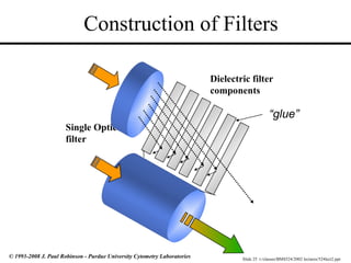
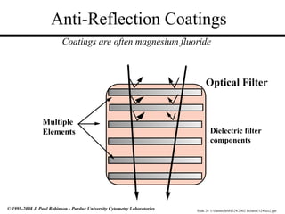
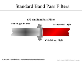
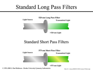
Slide 1 t:/classes/BMS524/2002 lectures/524lect2.ppt
© 1993-2008 J. Paul Robinson - Purdue University Cytometry Laboratories
BMS 524 - “Introduction to Confocal Microscopy and Image Analysis”
Lecture 4: The Principles of Microscopy III
Department of Basic Medical Sciences,
School of Veterinary Medicine
Weldon School of Biomedical Engineering
Purdue University
J. Paul Robinson, Ph.D.
SVM Professor of Cytomics
Professor of Immunopharmacology & Biomedical Engineering
Director, Purdue University Cytometry Laboratories, Purdue University
This lecture was last updated in January, 2008
You may download this PowerPoint lecture at http://tinyurl.com/2dr5p
Find other PUCL Educational Materials at http://www.cyto.purdue.edu/class
These slides are intended for use in a lecture series. Copies of the slides are distributed and students encouraged to take
their notes on these graphics. All material copyright J.Paul Robinson unless otherwise stated. No reproduction of this
material is permitted without the written permission of J. Paul Robinson. Except that our materials may be used in
not-for-profit educational institutions ith appropriate acknowledgement.
Slide 2 t:/classes/BMS524/2002 lectures/524lect2.ppt
© 1993-2008 J. Paul Robinson - Purdue University Cytometry Laboratories
Review
Properties of Light
• Refraction
• A Lens
• Refractive Index
• Numerical Aperture
• Resolution
• Aberrations
• Fluorescence
Slide 3 t:/classes/BMS524/2002 lectures/524lect2.ppt
© 1993-2008 J. Paul Robinson - Purdue University Cytometry Laboratories
Introduction to Lecture 3
Principles of Microscopy III
At the conclusion of this lecture you should:
• Understand the properties of light
• Know the properties of simple lenses
• Be familiar with microscope components
• Understand the nature of optical aberrations
• Understand how optical filters are designed
Slide 4 t:/classes/BMS524/2002 lectures/524lect2.ppt
© 1993-2008 J. Paul Robinson - Purdue University Cytometry Laboratories
Microscope Basics: Magnification
Images from http://micro.magnet.fsu.edu/index.html
I suggest you visit this site and go through the tutorials –
they are excellent!
Slide 5 t:/classes/BMS524/2002 lectures/524lect2.ppt
© 1993-2008 J. Paul Robinson - Purdue University Cytometry Laboratories
Refraction & Dispersion
Light is “bent” and the resultant colors separate (dispersion).
Red is least refracted, violet most refracted.
dispersion
Short wavelengths are “bent”
more than long wavelengths
refraction
Slide 6 t:/classes/BMS524/2002 lectures/524lect2.ppt
© 1993-2008 J. Paul Robinson - Purdue University Cytometry Laboratories
Reflection and Refraction
• Snell’s Law: The angle of
reflection (Ør) is equal to the
angle of incidence (Øi)
regardless of the surface
material
• The angle of the transmitted
beam (Øt) is dependent upon
the composition of the
material
t
i
r
Incident Beam
Reflected Beam
Transmitted
(refracted)Beam
n1 sin Øi = n2 sin Øt
The velocity of light in a material
of refractive index n is c/n
Slide 7 t:/classes/BMS524/2002 lectures/524lect2.ppt
© 1993-2008 J. Paul Robinson - Purdue University Cytometry Laboratories
Properties of thin Lenses
f
1
p
+
1
q
=
1
f
f
p q
Resolution (R) = 0.61 x

NA
Magnification =
q
p
(lateral)
(Rayleigh criterion)
Slide 8 t:/classes/BMS524/2002 lectures/524lect2.ppt
© 1993-2008 J. Paul Robinson - Purdue University Cytometry Laboratories
Microscope Components
• Ocular
• Objectives
• Condenser
• Numerical Aperture
• Refractive Index
• Aberrations
• Optical Filters
Slide 9 t:/classes/BMS524/2002 lectures/524lect2.ppt
© 1993-2008 J. Paul Robinson - Purdue University Cytometry Laboratories
Ocular - Eyepiece
• Essentially a projection lens (5x to 15x
magnification) Note: there is usually an adjustment call
the inter-pupillary distance on eyepieces for personal
focusing
• Huygenian
– Projects the image onto the retina of the eye
– your eye should not be right on the lens, but
back from it (eyecups create this space)
• Compensating
– designed to work with specific apochromatic or flat
field objectives - it is color compensated and cannot be
mixed with other objectives (or microscopes)
• Photo-adapter
– designed to project the image on the film in the camera
- usually a longer distance and lower magnification
from 0.5x to 5x
Images from http://micro.magnet.fsu.edu/index.html
Slide 10 t:/classes/BMS524/2002 lectures/524lect2.ppt
© 1993-2008 J. Paul Robinson - Purdue University Cytometry Laboratories
Condenser
• Has several purposes
– must focus the light onto the specimen
– fill the entire numerical aperture of the
objective (i.e. it must match the NA of the
objective)
• Most microscopes will have what is
termed an “Abbe” condenser (not
corrected for aberrations)
• Note if you exceed 1.0 NA objective,
you probably will need to use oil on the
condenser as well (except in inverted
scopes)
Slide 11 t:/classes/BMS524/2002 lectures/524lect2.ppt
© 1993-2008 J. Paul Robinson - Purdue University Cytometry Laboratories
Microscope Objectives
Images from http://micro.magnet.fsu.edu/index.html
Inside a Zeiss Objective
Slide 12 t:/classes/BMS524/2002 lectures/524lect2.ppt
© 1993-2008 J. Paul Robinson - Purdue University Cytometry Laboratories
• Monochromatic Aberrations
– Spherical aberration
– Coma
– Astigmatism
– Flatness of field
– Distortion
• Chromatic Aberrations
– Longitudinal aberration
– Lateral aberration
Sources of Aberrations
Images reproduced from:
http://micro.magnet.fsu.edu/
Slide 13 t:/classes/BMS524/2002 lectures/524lect2.ppt
© 1993-2008 J. Paul Robinson - Purdue University Cytometry Laboratories
Monochromatic Aberration - Spherical aberration
Generated by nonspherical wavefronts produced by the objective, and increased tube length, or inserted
objects such as coverslips, immersion oil, etc. Essentially, it is desirable only to use the center part of a
lens to avoid this problem.
F1 F2
F1
Corrected lens
Images reproduced from:
http://micro.magnet.fsu.edu/
Please go here and do the tutorials
Slide 14 t:/classes/BMS524/2002 lectures/524lect2.ppt
© 1993-2008 J. Paul Robinson - Purdue University Cytometry Laboratories
Monochromatic Aberrations - Coma
Coma is when a streaking radial distortion occurs for object points away from the optical axis. It should be noted that most
coma is experienced “off axis” and therefore, should be less of a problem in confocal systems.
1
2
3
Images reproduced from:
http://micro.magnet.fsu.edu/
Slide 15 t:/classes/BMS524/2002 lectures/524lect2.ppt
© 1993-2008 J. Paul Robinson - Purdue University Cytometry Laboratories
Image taken from http://micro.magnet.fsu.edu/primer/anatomy/aberrations.html
Images reproduced from:
http://micro.magnet.fsu.edu/
Images reproduced from:
http://micro.magnet.fsu.edu/
Slide 16 t:/classes/BMS524/2002 lectures/524lect2.ppt
© 1993-2008 J. Paul Robinson - Purdue University Cytometry Laboratories
Monochromatic Aberrations - Astigmatism
If a perfectly symmetrical image field is moved off axis,
it becomes either radially or tangentially elongated.
Images reproduced from:
http://micro.magnet.fsu.edu/
Slide 17 t:/classes/BMS524/2002 lectures/524lect2.ppt
© 1993-2008 J. Paul Robinson - Purdue University Cytometry Laboratories
Monochromatic Aberrations
– Flatness of Field
– Distortion
Lenses are spherical and since points of a flat image are focused
onto a spherical dish, the central and peripheral zones will not be in
focus. Complex Achromat and PLANAPOCHROMAT lenses
partially solve this problem but at reduced transmission.
DISTORTION occurs for objects components out of axis. Most
objectives correct to reduce distortion to less than 2% of the radial
distance from the axis.
Slide 18 t:/classes/BMS524/2002 lectures/524lect2.ppt
© 1993-2008 J. Paul Robinson - Purdue University Cytometry Laboratories
Useful Factoids
The intensity of light collected
The intensity of light collected decreases
decreases
as the square of the magnification
The intensity of light
The intensity of light increases
increases as the
as the
square of the numerical aperture
Thus when possible, use
Thus when possible, use low magnification
low magnification
and
and high NA
high NA objectives
objectives
Slide 19 t:/classes/BMS524/2002 lectures/524lect2.ppt
© 1993-2008 J. Paul Robinson - Purdue University Cytometry Laboratories
Fluorescence Microscopes
• Cannot view fluorescence emission in a single optical plane
• Generally use light sources of
much lower flux than confocal systems
• Are cheaper than confocal systems
• Give high quality photographic images
(actual photographs) whereas confocal
systems are restricted to small resolution images
Slide 20 t:/classes/BMS524/2002 lectures/524lect2.ppt
© 1993-2008 J. Paul Robinson - Purdue University Cytometry Laboratories
Fluorescent Microscope
Dichroic Filter
Objective
Arc Lamp
Emission Filter
Excitation Diaphragm
Ocular
Excitation Filter
EPI-Illumination
Slide 21 t:/classes/BMS524/2002 lectures/524lect2.ppt
© 1993-2008 J. Paul Robinson - Purdue University Cytometry Laboratories
Interference in Thin Films
• Small amounts of incident light are reflected at the
interface between two material of different RI
• Thickness of the material will alter the constructive or
destructive interference patterns - increasing or decreasing
certain wavelengths
• Optical filters can thus be created that “interfere” with the
normal transmission of light
Slide 22 t:/classes/BMS524/2002 lectures/524lect2.ppt
© 1993-2008 J. Paul Robinson - Purdue University Cytometry Laboratories
Interference and Diffraction: Gratings
• Diffraction essentially describes a departure from
theoretical geometric optics
• Thus a sharp objet casts an alternating shadow of
light and dark “patterns” because of interference
• Diffraction is the component that limits resolution
Slide 23 t:/classes/BMS524/2002 lectures/524lect2.ppt
© 1993-2008 J. Paul Robinson - Purdue University Cytometry Laboratories
Polarization & Phase: Interference
• Electric and magnetic fields are
vectors - i.e. they have both
magnitude and direction
• The inverse of the period
(wavelength) is the frequency in
Hz
Wavelength (period T)
Axis of
Magnetic Field
Axis of Propagation
Axis
of
Electric
Field
Modified from Shapiro “Practical Flow Cytometry” 3rd
Ed. Wiley-Liss, p78
Slide 24 t:/classes/BMS524/2002 lectures/524lect2.ppt
© 1993-2008 J. Paul Robinson - Purdue University Cytometry Laboratories
Interference
Constructive
Interference
Destructive
Interference
A
B
C
D
A+B
C+D
Amplitude
0o
90o
180o
270o
360o Wavelength
Figure modified from Shapiro “Practical Flow
Cytometry” 3rd
ed Wiley-Liss, p79
Here we have a phase difference of
180o
(2 radians) so the waves
cancel each other out
The frequency does
not change, but the
amplitude is doubled
Slide 25 t:/classes/BMS524/2002 lectures/524lect2.ppt
© 1993-2008 J. Paul Robinson - Purdue University Cytometry Laboratories
Construction of Filters
Dielectric filter
components
“glue”
Single Optical
filter
Slide 26 t:/classes/BMS524/2002 lectures/524lect2.ppt
© 1993-2008 J. Paul Robinson - Purdue University Cytometry Laboratories
Anti-Reflection Coatings
Optical Filter
Multiple
Elements
Coatings are often magnesium fluoride
Dielectric filter
components
Slide 27 t:/classes/BMS524/2002 lectures/524lect2.ppt
© 1993-2008 J. Paul Robinson - Purdue University Cytometry Laboratories
Standard Band Pass Filters
Transmitted Light
White Light Source
630 nm BandPass Filter
620 -640 nm Light
Slide 28 t:/classes/BMS524/2002 lectures/524lect2.ppt
© 1993-2008 J. Paul Robinson - Purdue University Cytometry Laboratories
Standard Long Pass Filters
Transmitted Light
Light Source
520 nm Long Pass Filter
>520 nm Light
Transmitted Light
Light Source
575 nm Short Pass Filter
<575 nm Light
Standard Short Pass Filters
Slide 29 t:/classes/BMS524/2002 lectures/524lect2.ppt
© 1993-2008 J. Paul Robinson - Purdue University Cytometry Laboratories
Optical Filters
Dichroic Filter/Mirror at 45 deg
Reflected light
Transmitted Light
Light Source
510 LP dichroic Mirror
Slide 30 t:/classes/BMS524/2002 lectures/524lect2.ppt
© 1993-2008 J. Paul Robinson - Purdue University Cytometry Laboratories
Filter Properties -Light Transmission
%T
Wavelength
100
0
50
Notch
Bandpass
Slide 31 t:/classes/BMS524/2002 lectures/524lect2.ppt
© 1993-2008 J. Paul Robinson - Purdue University Cytometry Laboratories
The intensity of the radiation is inversely proportional to the square of the distance traveled
Slide 32 t:/classes/BMS524/2002 lectures/524lect2.ppt
© 1993-2008 J. Paul Robinson - Purdue University Cytometry Laboratories
Lecture Summary
• Parts of the microscope (ocular, condenser)
• Objectives
• Numerical Aperture (NA)
• Refractive Index/refraction (RI)
• Aberrations
• Fluorescence microscope
• Properties of optical filters

Lect-4-Robinson general pathology inflammation

  • 1.
    Slide 1 t:/classes/BMS524/2002lectures/524lect2.ppt © 1993-2008 J. Paul Robinson - Purdue University Cytometry Laboratories BMS 524 - “Introduction to Confocal Microscopy and Image Analysis” Lecture 4: The Principles of Microscopy III Department of Basic Medical Sciences, School of Veterinary Medicine Weldon School of Biomedical Engineering Purdue University J. Paul Robinson, Ph.D. SVM Professor of Cytomics Professor of Immunopharmacology & Biomedical Engineering Director, Purdue University Cytometry Laboratories, Purdue University This lecture was last updated in January, 2008 You may download this PowerPoint lecture at http://tinyurl.com/2dr5p Find other PUCL Educational Materials at http://www.cyto.purdue.edu/class These slides are intended for use in a lecture series. Copies of the slides are distributed and students encouraged to take their notes on these graphics. All material copyright J.Paul Robinson unless otherwise stated. No reproduction of this material is permitted without the written permission of J. Paul Robinson. Except that our materials may be used in not-for-profit educational institutions ith appropriate acknowledgement.
  • 2.
    Slide 2 t:/classes/BMS524/2002lectures/524lect2.ppt © 1993-2008 J. Paul Robinson - Purdue University Cytometry Laboratories Review Properties of Light • Refraction • A Lens • Refractive Index • Numerical Aperture • Resolution • Aberrations • Fluorescence
  • 3.
    Slide 3 t:/classes/BMS524/2002lectures/524lect2.ppt © 1993-2008 J. Paul Robinson - Purdue University Cytometry Laboratories Introduction to Lecture 3 Principles of Microscopy III At the conclusion of this lecture you should: • Understand the properties of light • Know the properties of simple lenses • Be familiar with microscope components • Understand the nature of optical aberrations • Understand how optical filters are designed
  • 4.
    Slide 4 t:/classes/BMS524/2002lectures/524lect2.ppt © 1993-2008 J. Paul Robinson - Purdue University Cytometry Laboratories Microscope Basics: Magnification Images from http://micro.magnet.fsu.edu/index.html I suggest you visit this site and go through the tutorials – they are excellent!
  • 5.
    Slide 5 t:/classes/BMS524/2002lectures/524lect2.ppt © 1993-2008 J. Paul Robinson - Purdue University Cytometry Laboratories Refraction & Dispersion Light is “bent” and the resultant colors separate (dispersion). Red is least refracted, violet most refracted. dispersion Short wavelengths are “bent” more than long wavelengths refraction
  • 6.
    Slide 6 t:/classes/BMS524/2002lectures/524lect2.ppt © 1993-2008 J. Paul Robinson - Purdue University Cytometry Laboratories Reflection and Refraction • Snell’s Law: The angle of reflection (Ør) is equal to the angle of incidence (Øi) regardless of the surface material • The angle of the transmitted beam (Øt) is dependent upon the composition of the material t i r Incident Beam Reflected Beam Transmitted (refracted)Beam n1 sin Øi = n2 sin Øt The velocity of light in a material of refractive index n is c/n
  • 7.
    Slide 7 t:/classes/BMS524/2002lectures/524lect2.ppt © 1993-2008 J. Paul Robinson - Purdue University Cytometry Laboratories Properties of thin Lenses f 1 p + 1 q = 1 f f p q Resolution (R) = 0.61 x  NA Magnification = q p (lateral) (Rayleigh criterion)
  • 8.
    Slide 8 t:/classes/BMS524/2002lectures/524lect2.ppt © 1993-2008 J. Paul Robinson - Purdue University Cytometry Laboratories Microscope Components • Ocular • Objectives • Condenser • Numerical Aperture • Refractive Index • Aberrations • Optical Filters
  • 9.
    Slide 9 t:/classes/BMS524/2002lectures/524lect2.ppt © 1993-2008 J. Paul Robinson - Purdue University Cytometry Laboratories Ocular - Eyepiece • Essentially a projection lens (5x to 15x magnification) Note: there is usually an adjustment call the inter-pupillary distance on eyepieces for personal focusing • Huygenian – Projects the image onto the retina of the eye – your eye should not be right on the lens, but back from it (eyecups create this space) • Compensating – designed to work with specific apochromatic or flat field objectives - it is color compensated and cannot be mixed with other objectives (or microscopes) • Photo-adapter – designed to project the image on the film in the camera - usually a longer distance and lower magnification from 0.5x to 5x Images from http://micro.magnet.fsu.edu/index.html
  • 10.
    Slide 10 t:/classes/BMS524/2002lectures/524lect2.ppt © 1993-2008 J. Paul Robinson - Purdue University Cytometry Laboratories Condenser • Has several purposes – must focus the light onto the specimen – fill the entire numerical aperture of the objective (i.e. it must match the NA of the objective) • Most microscopes will have what is termed an “Abbe” condenser (not corrected for aberrations) • Note if you exceed 1.0 NA objective, you probably will need to use oil on the condenser as well (except in inverted scopes)
  • 11.
    Slide 11 t:/classes/BMS524/2002lectures/524lect2.ppt © 1993-2008 J. Paul Robinson - Purdue University Cytometry Laboratories Microscope Objectives Images from http://micro.magnet.fsu.edu/index.html Inside a Zeiss Objective
  • 12.
    Slide 12 t:/classes/BMS524/2002lectures/524lect2.ppt © 1993-2008 J. Paul Robinson - Purdue University Cytometry Laboratories • Monochromatic Aberrations – Spherical aberration – Coma – Astigmatism – Flatness of field – Distortion • Chromatic Aberrations – Longitudinal aberration – Lateral aberration Sources of Aberrations Images reproduced from: http://micro.magnet.fsu.edu/
  • 13.
    Slide 13 t:/classes/BMS524/2002lectures/524lect2.ppt © 1993-2008 J. Paul Robinson - Purdue University Cytometry Laboratories Monochromatic Aberration - Spherical aberration Generated by nonspherical wavefronts produced by the objective, and increased tube length, or inserted objects such as coverslips, immersion oil, etc. Essentially, it is desirable only to use the center part of a lens to avoid this problem. F1 F2 F1 Corrected lens Images reproduced from: http://micro.magnet.fsu.edu/ Please go here and do the tutorials
  • 14.
    Slide 14 t:/classes/BMS524/2002lectures/524lect2.ppt © 1993-2008 J. Paul Robinson - Purdue University Cytometry Laboratories Monochromatic Aberrations - Coma Coma is when a streaking radial distortion occurs for object points away from the optical axis. It should be noted that most coma is experienced “off axis” and therefore, should be less of a problem in confocal systems. 1 2 3 Images reproduced from: http://micro.magnet.fsu.edu/
  • 15.
    Slide 15 t:/classes/BMS524/2002lectures/524lect2.ppt © 1993-2008 J. Paul Robinson - Purdue University Cytometry Laboratories Image taken from http://micro.magnet.fsu.edu/primer/anatomy/aberrations.html Images reproduced from: http://micro.magnet.fsu.edu/ Images reproduced from: http://micro.magnet.fsu.edu/
  • 16.
    Slide 16 t:/classes/BMS524/2002lectures/524lect2.ppt © 1993-2008 J. Paul Robinson - Purdue University Cytometry Laboratories Monochromatic Aberrations - Astigmatism If a perfectly symmetrical image field is moved off axis, it becomes either radially or tangentially elongated. Images reproduced from: http://micro.magnet.fsu.edu/
  • 17.
    Slide 17 t:/classes/BMS524/2002lectures/524lect2.ppt © 1993-2008 J. Paul Robinson - Purdue University Cytometry Laboratories Monochromatic Aberrations – Flatness of Field – Distortion Lenses are spherical and since points of a flat image are focused onto a spherical dish, the central and peripheral zones will not be in focus. Complex Achromat and PLANAPOCHROMAT lenses partially solve this problem but at reduced transmission. DISTORTION occurs for objects components out of axis. Most objectives correct to reduce distortion to less than 2% of the radial distance from the axis.
  • 18.
    Slide 18 t:/classes/BMS524/2002lectures/524lect2.ppt © 1993-2008 J. Paul Robinson - Purdue University Cytometry Laboratories Useful Factoids The intensity of light collected The intensity of light collected decreases decreases as the square of the magnification as the square of the magnification The intensity of light The intensity of light increases increases as the as the square of the numerical aperture square of the numerical aperture Thus when possible, use Thus when possible, use low magnification low magnification and and high NA high NA objectives objectives
  • 19.
    Slide 19 t:/classes/BMS524/2002lectures/524lect2.ppt © 1993-2008 J. Paul Robinson - Purdue University Cytometry Laboratories Fluorescence Microscopes • Cannot view fluorescence emission in a single optical plane • Generally use light sources of much lower flux than confocal systems • Are cheaper than confocal systems • Give high quality photographic images (actual photographs) whereas confocal systems are restricted to small resolution images
  • 20.
    Slide 20 t:/classes/BMS524/2002lectures/524lect2.ppt © 1993-2008 J. Paul Robinson - Purdue University Cytometry Laboratories Fluorescent Microscope Dichroic Filter Objective Arc Lamp Emission Filter Excitation Diaphragm Ocular Excitation Filter EPI-Illumination
  • 21.
    Slide 21 t:/classes/BMS524/2002lectures/524lect2.ppt © 1993-2008 J. Paul Robinson - Purdue University Cytometry Laboratories Interference in Thin Films • Small amounts of incident light are reflected at the interface between two material of different RI • Thickness of the material will alter the constructive or destructive interference patterns - increasing or decreasing certain wavelengths • Optical filters can thus be created that “interfere” with the normal transmission of light
  • 22.
    Slide 22 t:/classes/BMS524/2002lectures/524lect2.ppt © 1993-2008 J. Paul Robinson - Purdue University Cytometry Laboratories Interference and Diffraction: Gratings • Diffraction essentially describes a departure from theoretical geometric optics • Thus a sharp objet casts an alternating shadow of light and dark “patterns” because of interference • Diffraction is the component that limits resolution
  • 23.
    Slide 23 t:/classes/BMS524/2002lectures/524lect2.ppt © 1993-2008 J. Paul Robinson - Purdue University Cytometry Laboratories Polarization & Phase: Interference • Electric and magnetic fields are vectors - i.e. they have both magnitude and direction • The inverse of the period (wavelength) is the frequency in Hz Wavelength (period T) Axis of Magnetic Field Axis of Propagation Axis of Electric Field Modified from Shapiro “Practical Flow Cytometry” 3rd Ed. Wiley-Liss, p78
  • 24.
    Slide 24 t:/classes/BMS524/2002lectures/524lect2.ppt © 1993-2008 J. Paul Robinson - Purdue University Cytometry Laboratories Interference Constructive Interference Destructive Interference A B C D A+B C+D Amplitude 0o 90o 180o 270o 360o Wavelength Figure modified from Shapiro “Practical Flow Cytometry” 3rd ed Wiley-Liss, p79 Here we have a phase difference of 180o (2 radians) so the waves cancel each other out The frequency does not change, but the amplitude is doubled
  • 25.
    Slide 25 t:/classes/BMS524/2002lectures/524lect2.ppt © 1993-2008 J. Paul Robinson - Purdue University Cytometry Laboratories Construction of Filters Dielectric filter components “glue” Single Optical filter
  • 26.
    Slide 26 t:/classes/BMS524/2002lectures/524lect2.ppt © 1993-2008 J. Paul Robinson - Purdue University Cytometry Laboratories Anti-Reflection Coatings Optical Filter Multiple Elements Coatings are often magnesium fluoride Dielectric filter components
  • 27.
    Slide 27 t:/classes/BMS524/2002lectures/524lect2.ppt © 1993-2008 J. Paul Robinson - Purdue University Cytometry Laboratories Standard Band Pass Filters Transmitted Light White Light Source 630 nm BandPass Filter 620 -640 nm Light
  • 28.
    Slide 28 t:/classes/BMS524/2002lectures/524lect2.ppt © 1993-2008 J. Paul Robinson - Purdue University Cytometry Laboratories Standard Long Pass Filters Transmitted Light Light Source 520 nm Long Pass Filter >520 nm Light Transmitted Light Light Source 575 nm Short Pass Filter <575 nm Light Standard Short Pass Filters
  • 29.
    Slide 29 t:/classes/BMS524/2002lectures/524lect2.ppt © 1993-2008 J. Paul Robinson - Purdue University Cytometry Laboratories Optical Filters Dichroic Filter/Mirror at 45 deg Reflected light Transmitted Light Light Source 510 LP dichroic Mirror
  • 30.
    Slide 30 t:/classes/BMS524/2002lectures/524lect2.ppt © 1993-2008 J. Paul Robinson - Purdue University Cytometry Laboratories Filter Properties -Light Transmission %T Wavelength 100 0 50 Notch Bandpass
  • 31.
    Slide 31 t:/classes/BMS524/2002lectures/524lect2.ppt © 1993-2008 J. Paul Robinson - Purdue University Cytometry Laboratories The intensity of the radiation is inversely proportional to the square of the distance traveled
  • 32.
    Slide 32 t:/classes/BMS524/2002lectures/524lect2.ppt © 1993-2008 J. Paul Robinson - Purdue University Cytometry Laboratories Lecture Summary • Parts of the microscope (ocular, condenser) • Objectives • Numerical Aperture (NA) • Refractive Index/refraction (RI) • Aberrations • Fluorescence microscope • Properties of optical filters