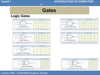
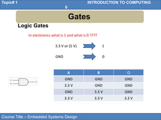
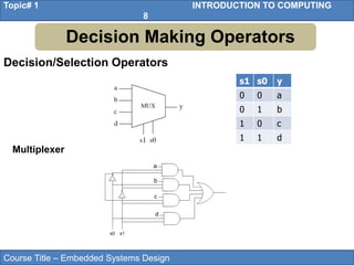
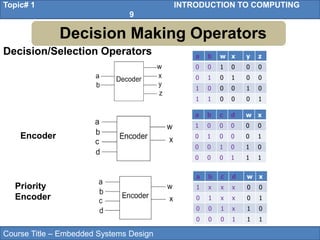
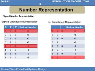
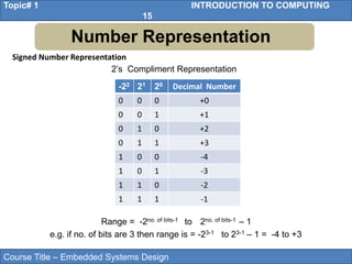
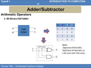
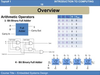
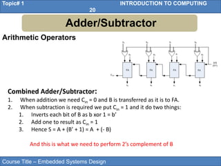
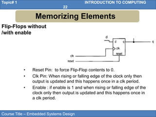
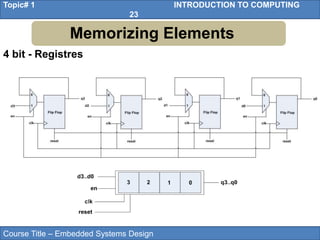
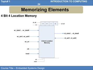
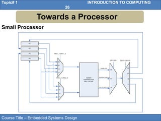
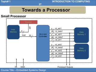
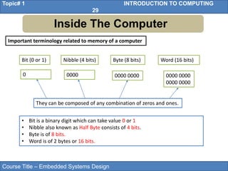
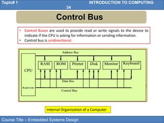
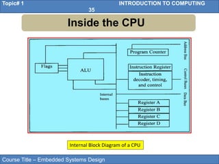
Embedded Systems Design
1
Topic #1
Introduction to Computing
2
Course Title – Embedded Systems Design
Topic# 1 INTRODUCTION TO COMPUTING
3
• Gates
• Decision Making Operators
• Number Representation
• Adder/ Subtractor
• Memorizing Elements
• Towards a Processor
• Inside the CPU
Outline
Course Title – Embedded Systems Design
Topic# 1 INTRODUCTION TO COMPUTING
4
• Gates
• Decision Making Operators
• Number Representation
• Adder/Subtractor
• Memorizing Elements
• Towards a Processor
• Inside the CPU
Outline
Course Title – Embedded Systems Design
Topic# 1 INTRODUCTION TO COMPUTING
5
Gates
Logic Gates
Course Title – Embedded Systems Design
Topic# 1 INTRODUCTION TO COMPUTING
6
Gates
Logic Gates
In electronics what is 1 and what is 0 ????
3.3 V or (5 V) 1
GND 0
A B Q
GND GND GND
3.3 V GND GND
GND 3.3 V GND
3.3 V 3.3 V 3.3 V
Course Title – Embedded Systems Design
Topic# 1 INTRODUCTION TO COMPUTING
7
• Gates
• Decision Making Operators
• Number Representation
• Adder/Subtractor
• Memorizing Elements
• Towards a Processor
• Inside the CPU
Outline
Course Title – Embedded Systems Design
Topic# 1 INTRODUCTION TO COMPUTING
8
s1 s0 y
0 0 a
0 1 b
1 0 c
1 1 d
Multiplexer
Decision/Selection Operators
Decision Making Operators
Course Title – Embedded Systems Design
Topic# 1 INTRODUCTION TO COMPUTING
9
a b w x y z
0 0 1 0 0 0
0 1 0 1 0 0
1 0 0 0 1 0
1 1 0 0 0 1
a b c d w x
1 0 0 0 0 0
0 1 0 0 0 1
0 0 1 0 1 0
0 0 0 1 1 1
Encoder
a b c d w x
1 x x x 0 0
0 1 x x 0 1
0 0 1 x 1 0
0 0 0 1 1 1
Priority
Encoder
Decision/Selection Operators
Decision Making Operators
Course Title – Embedded Systems Design
Topic# 1 INTRODUCTION TO COMPUTING
10
• Gates
• Decision Making Operators
• Number Representation
• Adder/Subtractor
• Memorizing Elements
• Towards a Processor
• Inside the CPU
Outline
Course Title – Embedded Systems Design
Topic# 1 INTRODUCTION TO COMPUTING
11
Number Representation
Unsigned Number Representation
 General Rule for Unsigned Representation of a system having x as
base (where x is 2 in binary system, 8 in octal system 10 in decimal
system and 16 in hexadecimal system)
 In x-base system total x characters to represent a number e.g in Binary
(base 2) 0 and 1 to represent a number , in octal 0 to 7, in decimal 0-9
and 0-9, A-F in hexadecimal system.
xn-1 ……x3 x2 x1 x0
Integer
. x-1 x-2 x-3 x-4 x-5……. x-m
. Fractional
Course Title – Embedded Systems Design
Topic# 1 INTRODUCTION TO COMPUTING
12
Number Representation
Unsigned Number Representation
 Example of Decimal System
……. 103 102 101 100
......1000 100 10 1
e.g a number in decimal system = (5003)10
= 5x10³ + 0x102 + 0x101+ 3x100
 Example of Binary System
……. 23 22 21 20
.....……8 4 2 1
e.g a number in binary = (1101) 2
In Decimal = 1x23 + 1x22 + 0x21+ 1x20
= 8+4+0+1= (13)10
Course Title – Embedded Systems Design
Topic# 1 INTRODUCTION TO COMPUTING
13
Number Representation
Unsigned Number Representation
Range of Unsigned number = 2no. of bits – 1 e.g. if no. of bits are 3 then range is
= 23 – 1 = 7
22 21 20 Decimal Number
0 0 0 0
0 0 1 1
0 1 0 2
0 1 1 3
1 0 0 4
1 0 1 5
1 1 0 6
1 1 1 7
Course Title – Embedded Systems Design
Topic# 1 INTRODUCTION TO COMPUTING
14
Number Representation
Signed Number Representation
Signed Magnitude Representation
S 21 20 Decimal Number
0 0 0 +0
0 0 1 +1
0 1 0 +2
0 1 1 +3
1 0 0 -0
1 0 1 -1
1 1 0 -2
1 1 1 -3
Decimal Number
0 0 0 +0
0 0 1 +1
0 1 0 +2
0 1 1 +3
1 0 0 -3
1 0 1 -2
1 1 0 -1
1 1 1 -0
1’s Compliment Representation
Course Title – Embedded Systems Design
Topic# 1 INTRODUCTION TO COMPUTING
15
Number Representation
Signed Number Representation
-22 21 20 Decimal Number
0 0 0 +0
0 0 1 +1
0 1 0 +2
0 1 1 +3
1 0 0 -4
1 0 1 -3
1 1 0 -2
1 1 1 -1
2’s Compliment Representation
Range = -2no. of bits-1 to 2no. of bits-1 – 1
e.g. if no. of bits are 3 then range is = -23-1 to 23-1 – 1 = -4 to +3
Course Title – Embedded Systems Design
Topic# 1 INTRODUCTION TO COMPUTING
16
• Gates
• Decision Making Operators
• Number Representation
• Adder/Subtractor
• Memorizing Elements
• Towards a Processor
• Inside the CPU
Outline
Course Title – Embedded Systems Design
Topic# 1 INTRODUCTION TO COMPUTING
17
Arithmetic Operators
1- Bit Binary Half Adder
A B S C
0 0 0 0
0 1 1 0
1 0 1 0
1 1 0 1
S
C
Half
Adder
S
C
A
B
Note:
Operand of One Bits
Total Sum of two bits i.e
1 bit sum and 1 bit carry
Adder/Subtractor
Course Title – Embedded Systems Design
Topic# 1 INTRODUCTION TO COMPUTING
18
Arithmetic Operators
1- Bit Binary Full Adder
4 - Bit Binary Full Adder
Full
Adder
S
Carry Out
A
B
Carry In
A B Cin S Cout
0 0 0 0 0
0 0 1 1 0
0 1 0 1 0
0 1 1 0 1
1 0 0 1 0
1 0 1 0 1
1 1 0 0 1
1 1 1 1 1
S4
Overview
Course Title – Embedded Systems Design
Topic# 1 INTRODUCTION TO COMPUTING
19
Adder/Subtractor
Subtractor:
To get C = A-B we can do C= A + (-B)
How –B can be achieved
• Take 1’s Complement of ‘B’ by inverting each bit
• Add 1 to 1’s complement of ‘B’
Can we modify adder circuit to behave as combined adder/subtractor.???
Yes why not …
Arithmetic Operators
Course Title – Embedded Systems Design
Topic# 1 INTRODUCTION TO COMPUTING
20
Arithmetic Operators
Adder/Subtractor
Combined Adder/Subtractor:
1. When addition we need Cin = 0 and B is transferred as it is to FA.
2. When subtraction is required we put Cin = 1 and it do two things:
1. Inverts each bit of B as b xor 1 = b’
2. Add one to result as Cin = 1
3. Hence S = A + (B’ + 1) = A + (- B)
And this is what we need to perform 2’s complement of B
Course Title – Embedded Systems Design
Topic# 1 INTRODUCTION TO COMPUTING
21
• Gates
• Decision Making Operators
• Number Representation
• Adder/Subtractor
• Memorizing Elements
• Towards a Processor
• Inside the CPU
Outline
Course Title – Embedded Systems Design
Topic# 1 INTRODUCTION TO COMPUTING
22
Flip-Flops without
/with enable
Memorizing Elements
• Reset Pin: to force Flip-Flop contents to 0.
• Clk Pin: When rising or falling edge of the clock only then
output is updated and this happens once in a clk period.
• Enable : if enable is 1 and when rising or falling edge of the
clock only then output is updated and this happens once in
a clk period.
d
Course Title – Embedded Systems Design
Topic# 1 INTRODUCTION TO COMPUTING
23
4 bit - Registres
Memorizing Elements
Course Title – Embedded Systems Design
Topic# 1 INTRODUCTION TO COMPUTING
24
4 Bit 4 Location Memory
Memorizing Elements
Course Title – Embedded Systems Design
Topic# 1 INTRODUCTION TO COMPUTING
25
• Gates
• Decision Making Operators
• Number Representation
• Adder/Subtractor
• Memorizing Elements
• Towards a Processor
• Inside the CPU
Outline
Course Title – Embedded Systems Design
Topic# 1 INTRODUCTION TO COMPUTING
26
Small Processor
Towards a Processor
Course Title – Embedded Systems Design
Topic# 1 INTRODUCTION TO COMPUTING
27
Small Processor
Towards a Processor
ALU and
Controller
32
4
24
4
rd_adr1
rd_data1
24
wr_adr1
wr_data1
1 wr_en1
4
24
4
rd_adr2
rd_data2
24
wr_adr2
wr_data2
1 wr_en2
Instr
Instr.
Memory
Counter
4
adr
Data
Memory 1
Data
Memory 2
Processor Outputs
clk reset
Course Title – Embedded Systems Design
Topic# 1 INTRODUCTION TO COMPUTING
28
• Gates
• Decision Making Operators
• Number Representation
• Adder/Subtractor
• Memorizing Elements
• Towards a Processor
• Inside the CPU
Outline
Course Title – Embedded Systems Design
Topic# 1 INTRODUCTION TO COMPUTING
29
Inside The Computer
Important terminology related to memory of a computer
Bit (0 or 1) Word (16 bits)
Nibble (4 bits) Byte (8 bits)
0 0000 0000 0000 0000 0000
0000 0000
• Bit is a binary digit which can take value 0 or 1
• Nibble also known as Half Byte consists of 4 bits.
• Byte is of 8 bits.
• Word is of 2 bytes or 16 bits.
They can be composed of any combination of zeros and ones.
Course Title – Embedded Systems Design
Topic# 1 INTRODUCTION TO COMPUTING
30
Memory Types
Two types of memory are commonly used in a computer
Random Access(RAM) Read Only Memory
Volatile Memory Non-Volatile Memory
• RAM is used by the computer for the temporary storage of programs that
it is running.
• ROM contains programs and information essential to operation of the
computer.
Data is lost when power turned off Data is not lost when power turned off
Course Title – Embedded Systems Design
Topic# 1 INTRODUCTION TO COMPUTING
31
Internal Organization of Computer
Internal working of computer can be broken into three parts
Central Processing Unit (CPU) Memory Input/Output (I/O)Devices
• Bus inside a computer carries information from place to place just as a
street bus carries people from place to place.
It executes information stored in
memory.
It provide means of communicating
with CPU via bus.
Course Title – Embedded Systems Design
Topic# 1 INTRODUCTION TO COMPUTING
32
Data Bus
• Data Buses are used to carry information in and out of a CPU.
• They provide a better pathway between the CPU and its external devices
(RAM, ROM, Printers etc.)
• Analogy: Data buses can be thought of as Highway Lanes, more lanes
means more traffic can pass.
• Construction of more lanes (more data buses) result in expensive
infrastructure (CPU and computer).
• Data buses are bidirectional. CPU can either use it to receive or send data.
• Processing power of computer is related to size of the data buses.
• 8 bit bus can send out 1 byte at a time.
• 16 bit can send out 2 bytes at a time, two times faster.
• Average size of data buses in CPUs between 8 and 64.
Course Title – Embedded Systems Design
Topic# 1 INTRODUCTION TO COMPUTING
33
Address Bus
• Address Buses are used to identify the devices and memory connected to
CPU.
• More addresses buses available means larger number of devices can be
addressed.
• Number of address buses for a CPU determines the number of locations
with which it can communicate.
• The number of locations is always equal to 2x, x is the number of address
lines.
• A CPU with 16 address lines provide a total of 65,536 (216) or 64K of
addressable memory.
• Each location can have a maximum of 1 byte of data. This is because all
general-purpose microprocessor CPUs are what is called byte addressable.
• Address bus is unidirectional, CPU only uses address bus to send out
addresses.
Course Title – Embedded Systems Design
Topic# 1 INTRODUCTION TO COMPUTING
34
Control Bus
• Control Buses are used to provide read or write signals to the device to
indicate if the CPU is asking for information or sending information.
• Control bus is unidirectional.
Internal Organization of a Computer
Course Title – Embedded Systems Design
Topic# 1 INTRODUCTION TO COMPUTING
35
Inside the CPU
Internal Block Diagram of a CPU
Course Title – Embedded Systems Design
Topic# 1 INTRODUCTION TO COMPUTING
36
Inside the CPU
• A program stored in memory provides instructions to the CPU to perform
an action. Action can simply be adding data or controlling a machine like a
robot.
• Function of the CPU is to fetch these instructions from memory and
execute them.
• Resources used by CPU to perform fetch and execute are:
• CPU uses registers to store the information temporarily. The information
could be values to be processed or the address of the value needed to be
fetched from the memory.
• Registers inside the CPU can be 8 bit, 16 bit, 32 bit or 64 bit registers.
More and bigger the registers, the better the CPU. More and bigger
registers means expensive CPUs.
Course Title – Embedded Systems Design
Topic# 1 INTRODUCTION TO COMPUTING
37
Inside the CPU
• Arithmetic Logical Unit (ALU) is responsible for performing arithmetic
functions such as add, subtract, multiply, and divide, and logical functions
such as AND, OR, and NOT.
• The function of the program counter is to point to the address of the next
instruction to be executed.
• The function of the instruction decoder is to interpret the instruction
fetched into the CPU. It is just a kind of dictionary, storing the meaning of
each instruction and what steps the CPU should take upon receiving a
given instruction.

Lec-1-2-27102021-122208am.pptx for embedded design

  • 1.
  • 2.
  • 3.
    Course Title –Embedded Systems Design Topic# 1 INTRODUCTION TO COMPUTING 3 • Gates • Decision Making Operators • Number Representation • Adder/ Subtractor • Memorizing Elements • Towards a Processor • Inside the CPU Outline
  • 4.
    Course Title –Embedded Systems Design Topic# 1 INTRODUCTION TO COMPUTING 4 • Gates • Decision Making Operators • Number Representation • Adder/Subtractor • Memorizing Elements • Towards a Processor • Inside the CPU Outline
  • 5.
    Course Title –Embedded Systems Design Topic# 1 INTRODUCTION TO COMPUTING 5 Gates Logic Gates
  • 6.
    Course Title –Embedded Systems Design Topic# 1 INTRODUCTION TO COMPUTING 6 Gates Logic Gates In electronics what is 1 and what is 0 ???? 3.3 V or (5 V) 1 GND 0 A B Q GND GND GND 3.3 V GND GND GND 3.3 V GND 3.3 V 3.3 V 3.3 V
  • 7.
    Course Title –Embedded Systems Design Topic# 1 INTRODUCTION TO COMPUTING 7 • Gates • Decision Making Operators • Number Representation • Adder/Subtractor • Memorizing Elements • Towards a Processor • Inside the CPU Outline
  • 8.
    Course Title –Embedded Systems Design Topic# 1 INTRODUCTION TO COMPUTING 8 s1 s0 y 0 0 a 0 1 b 1 0 c 1 1 d Multiplexer Decision/Selection Operators Decision Making Operators
  • 9.
    Course Title –Embedded Systems Design Topic# 1 INTRODUCTION TO COMPUTING 9 a b w x y z 0 0 1 0 0 0 0 1 0 1 0 0 1 0 0 0 1 0 1 1 0 0 0 1 a b c d w x 1 0 0 0 0 0 0 1 0 0 0 1 0 0 1 0 1 0 0 0 0 1 1 1 Encoder a b c d w x 1 x x x 0 0 0 1 x x 0 1 0 0 1 x 1 0 0 0 0 1 1 1 Priority Encoder Decision/Selection Operators Decision Making Operators
  • 10.
    Course Title –Embedded Systems Design Topic# 1 INTRODUCTION TO COMPUTING 10 • Gates • Decision Making Operators • Number Representation • Adder/Subtractor • Memorizing Elements • Towards a Processor • Inside the CPU Outline
  • 11.
    Course Title –Embedded Systems Design Topic# 1 INTRODUCTION TO COMPUTING 11 Number Representation Unsigned Number Representation  General Rule for Unsigned Representation of a system having x as base (where x is 2 in binary system, 8 in octal system 10 in decimal system and 16 in hexadecimal system)  In x-base system total x characters to represent a number e.g in Binary (base 2) 0 and 1 to represent a number , in octal 0 to 7, in decimal 0-9 and 0-9, A-F in hexadecimal system. xn-1 ……x3 x2 x1 x0 Integer . x-1 x-2 x-3 x-4 x-5……. x-m . Fractional
  • 12.
    Course Title –Embedded Systems Design Topic# 1 INTRODUCTION TO COMPUTING 12 Number Representation Unsigned Number Representation  Example of Decimal System ……. 103 102 101 100 ......1000 100 10 1 e.g a number in decimal system = (5003)10 = 5x10³ + 0x102 + 0x101+ 3x100  Example of Binary System ……. 23 22 21 20 .....……8 4 2 1 e.g a number in binary = (1101) 2 In Decimal = 1x23 + 1x22 + 0x21+ 1x20 = 8+4+0+1= (13)10
  • 13.
    Course Title –Embedded Systems Design Topic# 1 INTRODUCTION TO COMPUTING 13 Number Representation Unsigned Number Representation Range of Unsigned number = 2no. of bits – 1 e.g. if no. of bits are 3 then range is = 23 – 1 = 7 22 21 20 Decimal Number 0 0 0 0 0 0 1 1 0 1 0 2 0 1 1 3 1 0 0 4 1 0 1 5 1 1 0 6 1 1 1 7
  • 14.
    Course Title –Embedded Systems Design Topic# 1 INTRODUCTION TO COMPUTING 14 Number Representation Signed Number Representation Signed Magnitude Representation S 21 20 Decimal Number 0 0 0 +0 0 0 1 +1 0 1 0 +2 0 1 1 +3 1 0 0 -0 1 0 1 -1 1 1 0 -2 1 1 1 -3 Decimal Number 0 0 0 +0 0 0 1 +1 0 1 0 +2 0 1 1 +3 1 0 0 -3 1 0 1 -2 1 1 0 -1 1 1 1 -0 1’s Compliment Representation
  • 15.
    Course Title –Embedded Systems Design Topic# 1 INTRODUCTION TO COMPUTING 15 Number Representation Signed Number Representation -22 21 20 Decimal Number 0 0 0 +0 0 0 1 +1 0 1 0 +2 0 1 1 +3 1 0 0 -4 1 0 1 -3 1 1 0 -2 1 1 1 -1 2’s Compliment Representation Range = -2no. of bits-1 to 2no. of bits-1 – 1 e.g. if no. of bits are 3 then range is = -23-1 to 23-1 – 1 = -4 to +3
  • 16.
    Course Title –Embedded Systems Design Topic# 1 INTRODUCTION TO COMPUTING 16 • Gates • Decision Making Operators • Number Representation • Adder/Subtractor • Memorizing Elements • Towards a Processor • Inside the CPU Outline
  • 17.
    Course Title –Embedded Systems Design Topic# 1 INTRODUCTION TO COMPUTING 17 Arithmetic Operators 1- Bit Binary Half Adder A B S C 0 0 0 0 0 1 1 0 1 0 1 0 1 1 0 1 S C Half Adder S C A B Note: Operand of One Bits Total Sum of two bits i.e 1 bit sum and 1 bit carry Adder/Subtractor
  • 18.
    Course Title –Embedded Systems Design Topic# 1 INTRODUCTION TO COMPUTING 18 Arithmetic Operators 1- Bit Binary Full Adder 4 - Bit Binary Full Adder Full Adder S Carry Out A B Carry In A B Cin S Cout 0 0 0 0 0 0 0 1 1 0 0 1 0 1 0 0 1 1 0 1 1 0 0 1 0 1 0 1 0 1 1 1 0 0 1 1 1 1 1 1 S4 Overview
  • 19.
    Course Title –Embedded Systems Design Topic# 1 INTRODUCTION TO COMPUTING 19 Adder/Subtractor Subtractor: To get C = A-B we can do C= A + (-B) How –B can be achieved • Take 1’s Complement of ‘B’ by inverting each bit • Add 1 to 1’s complement of ‘B’ Can we modify adder circuit to behave as combined adder/subtractor.??? Yes why not … Arithmetic Operators
  • 20.
    Course Title –Embedded Systems Design Topic# 1 INTRODUCTION TO COMPUTING 20 Arithmetic Operators Adder/Subtractor Combined Adder/Subtractor: 1. When addition we need Cin = 0 and B is transferred as it is to FA. 2. When subtraction is required we put Cin = 1 and it do two things: 1. Inverts each bit of B as b xor 1 = b’ 2. Add one to result as Cin = 1 3. Hence S = A + (B’ + 1) = A + (- B) And this is what we need to perform 2’s complement of B
  • 21.
    Course Title –Embedded Systems Design Topic# 1 INTRODUCTION TO COMPUTING 21 • Gates • Decision Making Operators • Number Representation • Adder/Subtractor • Memorizing Elements • Towards a Processor • Inside the CPU Outline
  • 22.
    Course Title –Embedded Systems Design Topic# 1 INTRODUCTION TO COMPUTING 22 Flip-Flops without /with enable Memorizing Elements • Reset Pin: to force Flip-Flop contents to 0. • Clk Pin: When rising or falling edge of the clock only then output is updated and this happens once in a clk period. • Enable : if enable is 1 and when rising or falling edge of the clock only then output is updated and this happens once in a clk period. d
  • 23.
    Course Title –Embedded Systems Design Topic# 1 INTRODUCTION TO COMPUTING 23 4 bit - Registres Memorizing Elements
  • 24.
    Course Title –Embedded Systems Design Topic# 1 INTRODUCTION TO COMPUTING 24 4 Bit 4 Location Memory Memorizing Elements
  • 25.
    Course Title –Embedded Systems Design Topic# 1 INTRODUCTION TO COMPUTING 25 • Gates • Decision Making Operators • Number Representation • Adder/Subtractor • Memorizing Elements • Towards a Processor • Inside the CPU Outline
  • 26.
    Course Title –Embedded Systems Design Topic# 1 INTRODUCTION TO COMPUTING 26 Small Processor Towards a Processor
  • 27.
    Course Title –Embedded Systems Design Topic# 1 INTRODUCTION TO COMPUTING 27 Small Processor Towards a Processor ALU and Controller 32 4 24 4 rd_adr1 rd_data1 24 wr_adr1 wr_data1 1 wr_en1 4 24 4 rd_adr2 rd_data2 24 wr_adr2 wr_data2 1 wr_en2 Instr Instr. Memory Counter 4 adr Data Memory 1 Data Memory 2 Processor Outputs clk reset
  • 28.
    Course Title –Embedded Systems Design Topic# 1 INTRODUCTION TO COMPUTING 28 • Gates • Decision Making Operators • Number Representation • Adder/Subtractor • Memorizing Elements • Towards a Processor • Inside the CPU Outline
  • 29.
    Course Title –Embedded Systems Design Topic# 1 INTRODUCTION TO COMPUTING 29 Inside The Computer Important terminology related to memory of a computer Bit (0 or 1) Word (16 bits) Nibble (4 bits) Byte (8 bits) 0 0000 0000 0000 0000 0000 0000 0000 • Bit is a binary digit which can take value 0 or 1 • Nibble also known as Half Byte consists of 4 bits. • Byte is of 8 bits. • Word is of 2 bytes or 16 bits. They can be composed of any combination of zeros and ones.
  • 30.
    Course Title –Embedded Systems Design Topic# 1 INTRODUCTION TO COMPUTING 30 Memory Types Two types of memory are commonly used in a computer Random Access(RAM) Read Only Memory Volatile Memory Non-Volatile Memory • RAM is used by the computer for the temporary storage of programs that it is running. • ROM contains programs and information essential to operation of the computer. Data is lost when power turned off Data is not lost when power turned off
  • 31.
    Course Title –Embedded Systems Design Topic# 1 INTRODUCTION TO COMPUTING 31 Internal Organization of Computer Internal working of computer can be broken into three parts Central Processing Unit (CPU) Memory Input/Output (I/O)Devices • Bus inside a computer carries information from place to place just as a street bus carries people from place to place. It executes information stored in memory. It provide means of communicating with CPU via bus.
  • 32.
    Course Title –Embedded Systems Design Topic# 1 INTRODUCTION TO COMPUTING 32 Data Bus • Data Buses are used to carry information in and out of a CPU. • They provide a better pathway between the CPU and its external devices (RAM, ROM, Printers etc.) • Analogy: Data buses can be thought of as Highway Lanes, more lanes means more traffic can pass. • Construction of more lanes (more data buses) result in expensive infrastructure (CPU and computer). • Data buses are bidirectional. CPU can either use it to receive or send data. • Processing power of computer is related to size of the data buses. • 8 bit bus can send out 1 byte at a time. • 16 bit can send out 2 bytes at a time, two times faster. • Average size of data buses in CPUs between 8 and 64.
  • 33.
    Course Title –Embedded Systems Design Topic# 1 INTRODUCTION TO COMPUTING 33 Address Bus • Address Buses are used to identify the devices and memory connected to CPU. • More addresses buses available means larger number of devices can be addressed. • Number of address buses for a CPU determines the number of locations with which it can communicate. • The number of locations is always equal to 2x, x is the number of address lines. • A CPU with 16 address lines provide a total of 65,536 (216) or 64K of addressable memory. • Each location can have a maximum of 1 byte of data. This is because all general-purpose microprocessor CPUs are what is called byte addressable. • Address bus is unidirectional, CPU only uses address bus to send out addresses.
  • 34.
    Course Title –Embedded Systems Design Topic# 1 INTRODUCTION TO COMPUTING 34 Control Bus • Control Buses are used to provide read or write signals to the device to indicate if the CPU is asking for information or sending information. • Control bus is unidirectional. Internal Organization of a Computer
  • 35.
    Course Title –Embedded Systems Design Topic# 1 INTRODUCTION TO COMPUTING 35 Inside the CPU Internal Block Diagram of a CPU
  • 36.
    Course Title –Embedded Systems Design Topic# 1 INTRODUCTION TO COMPUTING 36 Inside the CPU • A program stored in memory provides instructions to the CPU to perform an action. Action can simply be adding data or controlling a machine like a robot. • Function of the CPU is to fetch these instructions from memory and execute them. • Resources used by CPU to perform fetch and execute are: • CPU uses registers to store the information temporarily. The information could be values to be processed or the address of the value needed to be fetched from the memory. • Registers inside the CPU can be 8 bit, 16 bit, 32 bit or 64 bit registers. More and bigger the registers, the better the CPU. More and bigger registers means expensive CPUs.
  • 37.
    Course Title –Embedded Systems Design Topic# 1 INTRODUCTION TO COMPUTING 37 Inside the CPU • Arithmetic Logical Unit (ALU) is responsible for performing arithmetic functions such as add, subtract, multiply, and divide, and logical functions such as AND, OR, and NOT. • The function of the program counter is to point to the address of the next instruction to be executed. • The function of the instruction decoder is to interpret the instruction fetched into the CPU. It is just a kind of dictionary, storing the meaning of each instruction and what steps the CPU should take upon receiving a given instruction.