Download free for 30 days
Sign in
Upload
Language (EN)
Support
Business
Mobile
Social Media
Marketing
Technology
Art & Photos
Career
Design
Education
Presentations & Public Speaking
Government & Nonprofit
Healthcare
Internet
Law
Leadership & Management
Automotive
Engineering
Software
Recruiting & HR
Retail
Sales
Services
Science
Small Business & Entrepreneurship
Food
Environment
Economy & Finance
Data & Analytics
Investor Relations
Sports
Spiritual
News & Politics
Travel
Self Improvement
Real Estate
Entertainment & Humor
Health & Medicine
Devices & Hardware
Lifestyle
Change Language
Language
English
Español
Português
Français
Deutsche
Cancel
Save
Submit search
EN
Uploaded by
uhoneprincemulaudzi
PPTX, PDF
16 views
Learning Unit 6 Unified Modeling Ls.pptx
explains the UML diagrams
Education
◦
Read more
0
Save
Share
Embed
Embed presentation
Download
Download to read offline
1
/ 70
2
/ 70
3
/ 70
4
/ 70
5
/ 70
6
/ 70
7
/ 70
8
/ 70
9
/ 70
10
/ 70
11
/ 70
12
/ 70
13
/ 70
14
/ 70
15
/ 70
16
/ 70
17
/ 70
18
/ 70
19
/ 70
20
/ 70
21
/ 70
22
/ 70
23
/ 70
24
/ 70
25
/ 70
26
/ 70
27
/ 70
28
/ 70
29
/ 70
30
/ 70
31
/ 70
32
/ 70
33
/ 70
34
/ 70
35
/ 70
36
/ 70
37
/ 70
38
/ 70
39
/ 70
40
/ 70
41
/ 70
42
/ 70
43
/ 70
44
/ 70
45
/ 70
46
/ 70
47
/ 70
48
/ 70
49
/ 70
50
/ 70
51
/ 70
52
/ 70
53
/ 70
54
/ 70
55
/ 70
56
/ 70
57
/ 70
58
/ 70
59
/ 70
60
/ 70
61
/ 70
62
/ 70
63
/ 70
64
/ 70
65
/ 70
66
/ 70
67
/ 70
68
/ 70
69
/ 70
70
/ 70
More Related Content
PPT
Sadcw 6e chapter4
by
Matthew McKenzie
PPTX
Sadcw 7e chapter04_recorded
by
LamineKaba6
PPTX
Sadcw 7e chapter04(1)
by
LamineKaba6
PDF
Systems Analysis and Design in a Changing World, Fourth Edition
by
Jhon Keneth Namias
PPT
05 si(systems analysis and design )
by
Nurdin Al-Azies
PPT
Systems Analysis and Design in a Changing World, Fifth Edition_Chapter 7.ppt
by
mnassar75g
PPT
Modeling System Requirement
by
Henhen Lukmana
DOCX
Hi Navish,Here I attached the feedback form. I personally feel.docx
by
pooleavelina
Sadcw 6e chapter4
by
Matthew McKenzie
Sadcw 7e chapter04_recorded
by
LamineKaba6
Sadcw 7e chapter04(1)
by
LamineKaba6
Systems Analysis and Design in a Changing World, Fourth Edition
by
Jhon Keneth Namias
05 si(systems analysis and design )
by
Nurdin Al-Azies
Systems Analysis and Design in a Changing World, Fifth Edition_Chapter 7.ppt
by
mnassar75g
Modeling System Requirement
by
Henhen Lukmana
Hi Navish,Here I attached the feedback form. I personally feel.docx
by
pooleavelina
Similar to Learning Unit 6 Unified Modeling Ls.pptx
PPTX
Object-Oriented Design Fundamentals.pptx
by
RaflyRizky2
PPTX
SADCW_7e_Chapter02.pptx
by
SiphiweMakaNtandOlwe
PPT
Sadcw 6e chapter3
by
Matthew McKenzie
PPTX
SADCW_7e_Chapter03.pptx
by
SiphiweMakaNtandOlwe
PDF
Systems Analysis and Design in a Changing World 7th Edition Satzinger Solutio...
by
agengarayhon
PDF
IM-7ed-Chapter02-done.pdf
by
Vahid95
PPTX
Chapter 2
by
LamineKaba6
PPT
11 si(systems analysis and design )
by
Nurdin Al-Azies
PDF
Chapter01_software_design_concept_slide.pdf
by
Mostafa Taghizade
PPTX
Sadcw 7e chapter01-done
by
LamineKaba6
PPT
The Traditional Approach to Requirement
by
Henhen Lukmana
PPT
Sadcw 6e chapter2
by
Matthew McKenzie
PPTX
SADCW_7e_Chapter01.pptx
by
SiphiweMakaNtandOlwe
PPTX
System analysis and Design chapter 8 exercise
by
devinawidjaja08
PPTX
Strategic plan
by
sarpedaniel
PPT
James hall ch 14
by
David Julian
PDF
Systems Analysis and Design in a Changing World, Fourth Edition
by
Jhon Keneth Namias
PPTX
Sadcw 7e chapter03-done(1)
by
LamineKaba6
PPTX
DIY ERM (Do-It-Yourself Electronic Resources Management) for the Small Library
by
NASIG
PPT
CPIS351-chapter9.ppt contains about system analysis and design
by
NaglaaAbdelhady
Object-Oriented Design Fundamentals.pptx
by
RaflyRizky2
SADCW_7e_Chapter02.pptx
by
SiphiweMakaNtandOlwe
Sadcw 6e chapter3
by
Matthew McKenzie
SADCW_7e_Chapter03.pptx
by
SiphiweMakaNtandOlwe
Systems Analysis and Design in a Changing World 7th Edition Satzinger Solutio...
by
agengarayhon
IM-7ed-Chapter02-done.pdf
by
Vahid95
Chapter 2
by
LamineKaba6
11 si(systems analysis and design )
by
Nurdin Al-Azies
Chapter01_software_design_concept_slide.pdf
by
Mostafa Taghizade
Sadcw 7e chapter01-done
by
LamineKaba6
The Traditional Approach to Requirement
by
Henhen Lukmana
Sadcw 6e chapter2
by
Matthew McKenzie
SADCW_7e_Chapter01.pptx
by
SiphiweMakaNtandOlwe
System analysis and Design chapter 8 exercise
by
devinawidjaja08
Strategic plan
by
sarpedaniel
James hall ch 14
by
David Julian
Systems Analysis and Design in a Changing World, Fourth Edition
by
Jhon Keneth Namias
Sadcw 7e chapter03-done(1)
by
LamineKaba6
DIY ERM (Do-It-Yourself Electronic Resources Management) for the Small Library
by
NASIG
CPIS351-chapter9.ppt contains about system analysis and design
by
NaglaaAbdelhady
Recently uploaded
PDF
Ketogenic diet in Epilepsy in children..
by
mirzasania0810
PDF
Types of Vegetable Gardens, College of Agriculture Balaghat.pdf
by
bisensharad
PDF
Models of Teaching - TNTEU - B.Ed I Semester - Teaching and Learning - BD1TL ...
by
Dr Raja Mohammed T
PPTX
Role of the Uninstall Hook in Odoo 18 Module Cleanup
by
Celine George
PDF
Prescription Writing- Elements, Parts, and Exercises
by
Dr. Ishita Agarwal
PDF
All Students Workshop 25 Yoga Wellness by LDMMIA
by
©LDMMIA, ©Reiki Yoga
PDF
Unit-III pdf (Basic listening Skill, Effective Writing Communication & Writin...
by
SayyadTarannum
PPTX
Pain. definition, causes, factor influencing pain & pain assessment.pptx
by
Pompi Begum
PPTX
Details of Muscular-and-Nervous-Tissues.pptx
by
Ashish Umale
PPTX
CLASS -9 POLITICAL SCIENCE PPT CHAPTER -5 DEMOCRATIC RIGHTS.pptx
by
dushyantchavhan
PPTX
What is the Post load hook in Odoo 18
by
Celine George
PDF
Handwritten notes of Toxicity 1. Genotoxicity 2 Carcinogenicity 3 Teratogenic...
by
jagdeepsinghynr7
PPTX
Searching in PubMed andCochrane_Practical Presentation.pptx
by
Systematic Reviews Network (SRN)
PPTX
SOCIAL SYSTEM.......................pptx
by
AneetaSharma15
PDF
NAVIGATE PHARMACY CAREER OPPORTUNITIES.pdf
by
Md. Zakaria Faruki
PPTX
Unit I — Introduction to Anatomical Terms and Organization of the Human Body
by
RAKESH SAJJAN
PPTX
Hypothesis. its definition and typrs pptx
by
Makarand Joshi
PDF
Principles and Practices of GST 2.0 Study material
by
Sri Ramakrishna College of Arts and science
PDF
The Tale of Melon City poem ppt by Sahasra
by
bitrasahasra
PDF
1ST APPLICATION FOR ANNULMENT (4)8787666.pdf
by
konstantinantountoum1
Ketogenic diet in Epilepsy in children..
by
mirzasania0810
Types of Vegetable Gardens, College of Agriculture Balaghat.pdf
by
bisensharad
Models of Teaching - TNTEU - B.Ed I Semester - Teaching and Learning - BD1TL ...
by
Dr Raja Mohammed T
Role of the Uninstall Hook in Odoo 18 Module Cleanup
by
Celine George
Prescription Writing- Elements, Parts, and Exercises
by
Dr. Ishita Agarwal
All Students Workshop 25 Yoga Wellness by LDMMIA
by
©LDMMIA, ©Reiki Yoga
Unit-III pdf (Basic listening Skill, Effective Writing Communication & Writin...
by
SayyadTarannum
Pain. definition, causes, factor influencing pain & pain assessment.pptx
by
Pompi Begum
Details of Muscular-and-Nervous-Tissues.pptx
by
Ashish Umale
CLASS -9 POLITICAL SCIENCE PPT CHAPTER -5 DEMOCRATIC RIGHTS.pptx
by
dushyantchavhan
What is the Post load hook in Odoo 18
by
Celine George
Handwritten notes of Toxicity 1. Genotoxicity 2 Carcinogenicity 3 Teratogenic...
by
jagdeepsinghynr7
Searching in PubMed andCochrane_Practical Presentation.pptx
by
Systematic Reviews Network (SRN)
SOCIAL SYSTEM.......................pptx
by
AneetaSharma15
NAVIGATE PHARMACY CAREER OPPORTUNITIES.pdf
by
Md. Zakaria Faruki
Unit I — Introduction to Anatomical Terms and Organization of the Human Body
by
RAKESH SAJJAN
Hypothesis. its definition and typrs pptx
by
Makarand Joshi
Principles and Practices of GST 2.0 Study material
by
Sri Ramakrishna College of Arts and science
The Tale of Melon City poem ppt by Sahasra
by
bitrasahasra
1ST APPLICATION FOR ANNULMENT (4)8787666.pdf
by
konstantinantountoum1
Learning Unit 6 Unified Modeling Ls.pptx
1.
1 Chapter 4 Systems Analysis
and Design in a Changing World, 7th Edition – Chapter 4 ©2016. Cengage Learning. All rights reserved.
2.
2 Systems Analysis and
Design in a Changing World, 7th Edition – Chapter 4 ©2016. Cengage Learning. All rights reserved. DomainModeling Systems Analysis and Design in a Changing World 7th Ed Satzinger, Jackson & Burd Chapter 4
3.
3 Systems Analysis and
Design in a Changing World, 7th Edition – Chapter 4 ©2016. Cengage Learning. All rights reserved. Chapter 4 Outline “Things” in the Problem Domain The Entity-Relationship Diagram The Domain Model Class Diagram The State Machine Diagram – Identifying Object Behavior
4.
Learning Objectives Explain how
the concept of “things” in the problem domain also define requirements Identify and analyze data entities and domain classes needed in the system Read, interpret, and create an entity-relationship diagram Read, interpret, and create a domain model class diagram Understand the domain model class diagram for the RMO Consolidated Sales and Marketing System Read, interpret, and create a state machine diagram that models object behavior Systems Analysis and Design in a Changing World, 7th Edition – Chapter 4 ©2016. Cengage Learning. All rights reserved. 4
5.
Overview This chapter focuses
on another key concept for defining requirements— data entities or domain classes In the RMO Tradeshow System from Chapter 1, some domain classes are Supplier, Product, and Contact In this chapter’s opening case Waiters on Call, examples of domain classes are Restaurants, Menu Items, Customers, Orders, Drivers, Routes, and Payments Systems Analysis and Design in a Changing World, 7th Edition – Chapter 4 ©2016. Cengage Learning. All rights reserved. 5
6.
ThingsintheProblemDomain Problem domain—the specific
area (or domain) of the users’ business need that is within the scope of the new system. “Things” are those items users work with when accomplishing tasks that need to be remembered Examples of “Things” are products, sales, shippers, customers, invoices, payments, etc. These “Things” are modeled as domain classes or data entities In this course, we will call them domain classes. In database class you may call them data entities Systems Analysis and Design in a Changing World, 7th Edition – Chapter 4 ©2016. Cengage Learning. All rights reserved. 6
7.
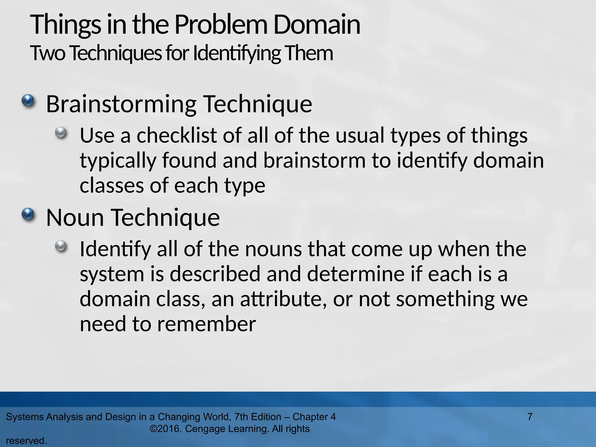
ThingsintheProblemDomain TwoTechniquesforIdentifyingThem Brainstorming Technique Use a
checklist of all of the usual types of things typically found and brainstorm to identify domain classes of each type Noun Technique Identify all of the nouns that come up when the system is described and determine if each is a domain class, an attribute, or not something we need to remember Systems Analysis and Design in a Changing World, 7th Edition – Chapter 4 ©2016. Cengage Learning. All rights reserved. 7
8.
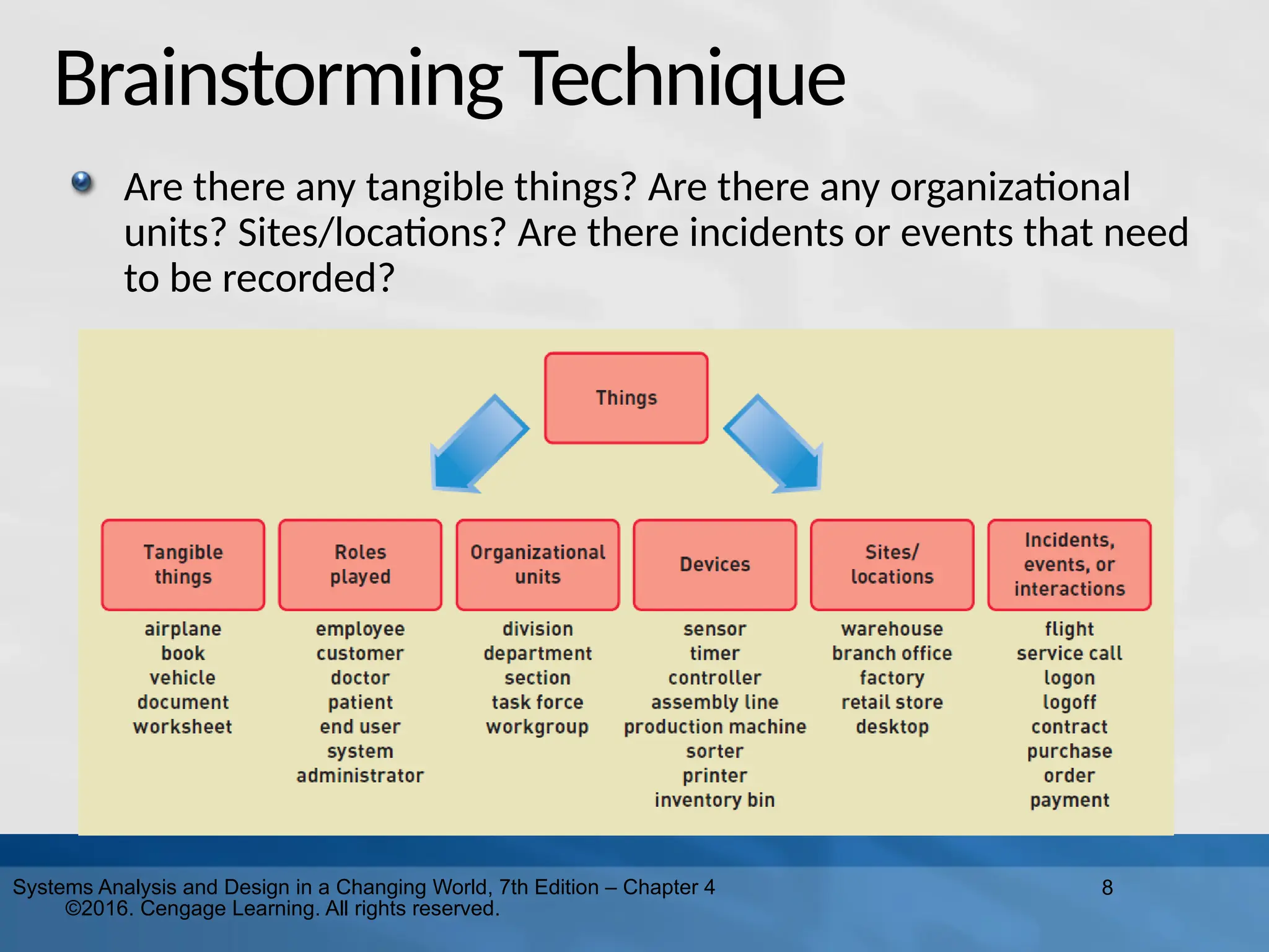
8 Systems Analysis and
Design in a Changing World, 7th Edition – Chapter 4 ©2016. Cengage Learning. All rights reserved. Brainstorming Technique Are there any tangible things? Are there any organizational units? Sites/locations? Are there incidents or events that need to be recorded?
9.
9 Systems Analysis and
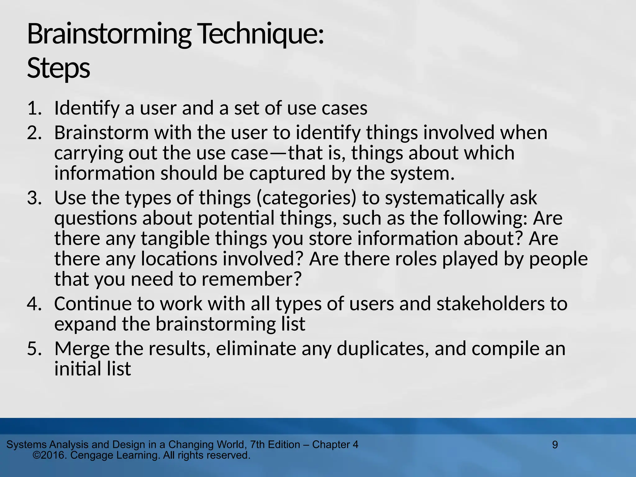
Design in a Changing World, 7th Edition – Chapter 4 ©2016. Cengage Learning. All rights reserved. BrainstormingTechnique: Steps 1. Identify a user and a set of use cases 2. Brainstorm with the user to identify things involved when carrying out the use case—that is, things about which information should be captured by the system. 3. Use the types of things (categories) to systematically ask questions about potential things, such as the following: Are there any tangible things you store information about? Are there any locations involved? Are there roles played by people that you need to remember? 4. Continue to work with all types of users and stakeholders to expand the brainstorming list 5. Merge the results, eliminate any duplicates, and compile an initial list
10.
10 Systems Analysis and
Design in a Changing World, 7th Edition – Chapter 4 ©2016. Cengage Learning. All rights reserved. TheNounTechnique A technique to identify problem domain classes (things) by finding, classifying, and refining a list of nouns that come up in in discussions or documents Popular technique. Systematic. Does end up with long lists and many nouns that are not things that need to be stored by the system Difficulty identifying synonyms and things that are really attributes Good place to start when there are no users available to help brainstorm
11.
11 Systems Analysis and
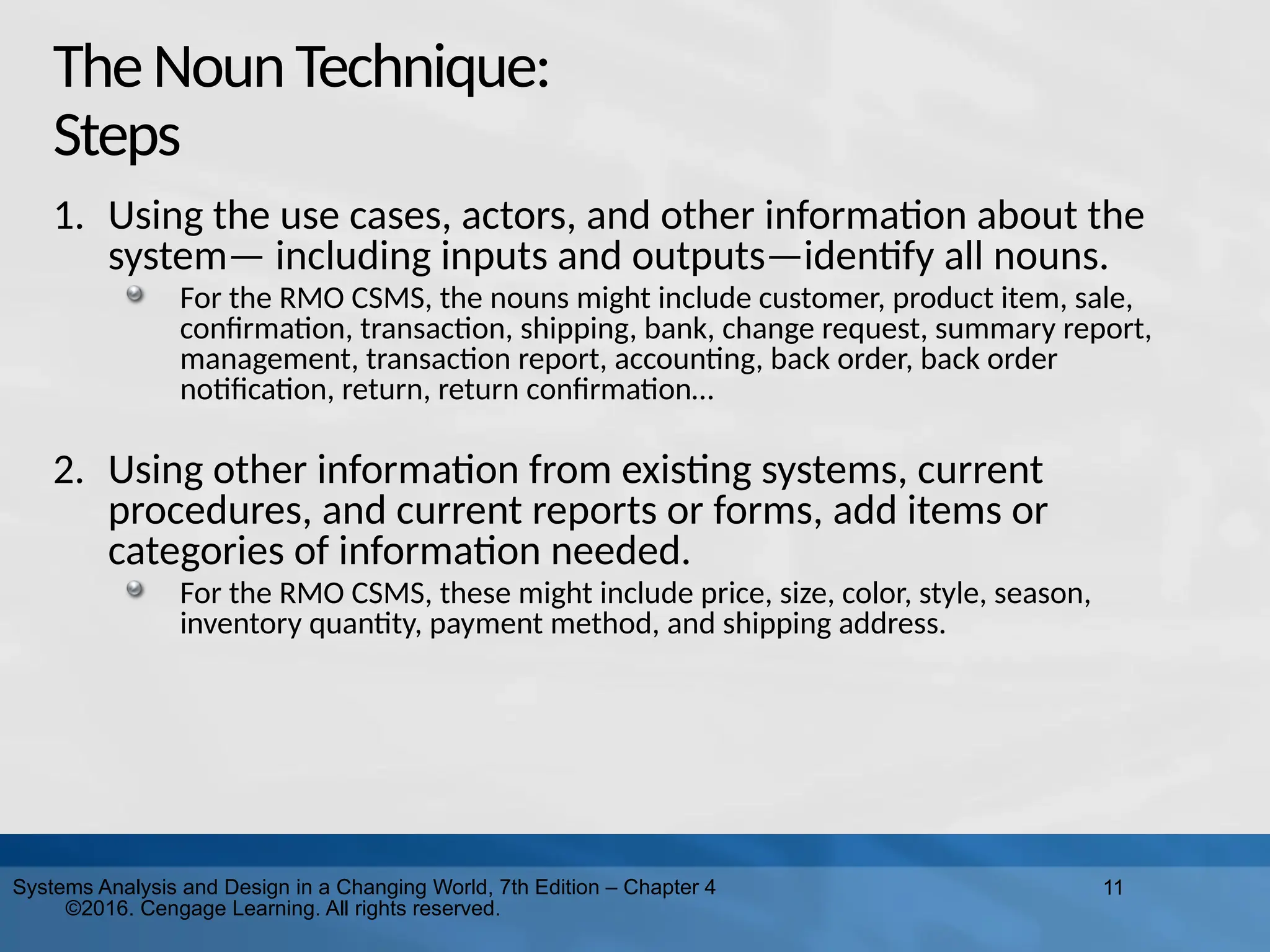
Design in a Changing World, 7th Edition – Chapter 4 ©2016. Cengage Learning. All rights reserved. TheNounTechnique: Steps 1. Using the use cases, actors, and other information about the system— including inputs and outputs—identify all nouns. For the RMO CSMS, the nouns might include customer, product item, sale, confirmation, transaction, shipping, bank, change request, summary report, management, transaction report, accounting, back order, back order notification, return, return confirmation… 2. Using other information from existing systems, current procedures, and current reports or forms, add items or categories of information needed. For the RMO CSMS, these might include price, size, color, style, season, inventory quantity, payment method, and shipping address.
12.
12 Systems Analysis and
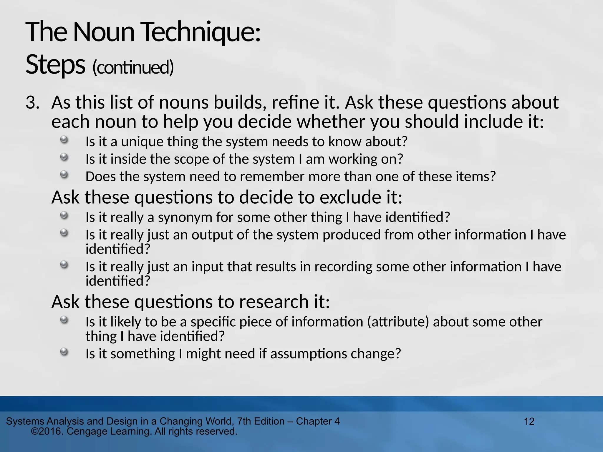
Design in a Changing World, 7th Edition – Chapter 4 ©2016. Cengage Learning. All rights reserved. TheNounTechnique: Steps (continued) 3. As this list of nouns builds, refine it. Ask these questions about each noun to help you decide whether you should include it: Is it a unique thing the system needs to know about? Is it inside the scope of the system I am working on? Does the system need to remember more than one of these items? Ask these questions to decide to exclude it: Is it really a synonym for some other thing I have identified? Is it really just an output of the system produced from other information I have identified? Is it really just an input that results in recording some other information I have identified? Ask these questions to research it: Is it likely to be a specific piece of information (attribute) about some other thing I have identified? Is it something I might need if assumptions change?
13.
13 Systems Analysis and
Design in a Changing World, 7th Edition – Chapter 4 ©2016. Cengage Learning. All rights reserved. TheNounTechnique: Steps (continued) 4. Create a master list of all nouns identified and then note whether each one should be included, excluded, or researched further. 5. Review the list with users, stakeholders, and team members and then define the list of things in the problem domain.
14.
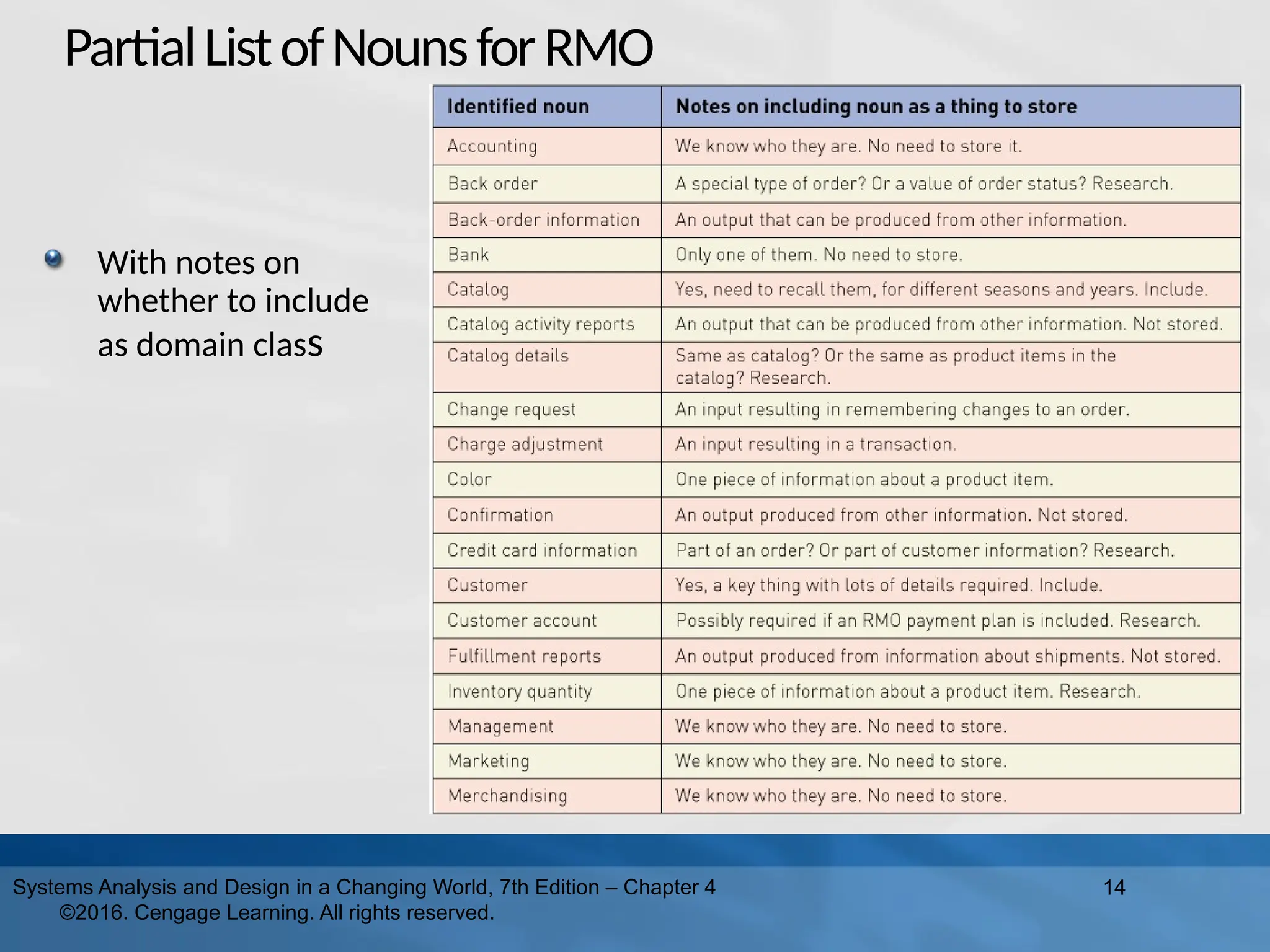
PartialListofNounsforRMO With notes on whether
to include as domain class 14 Systems Analysis and Design in a Changing World, 7th Edition – Chapter 4 ©2016. Cengage Learning. All rights reserved.
15.
15 Systems Analysis and
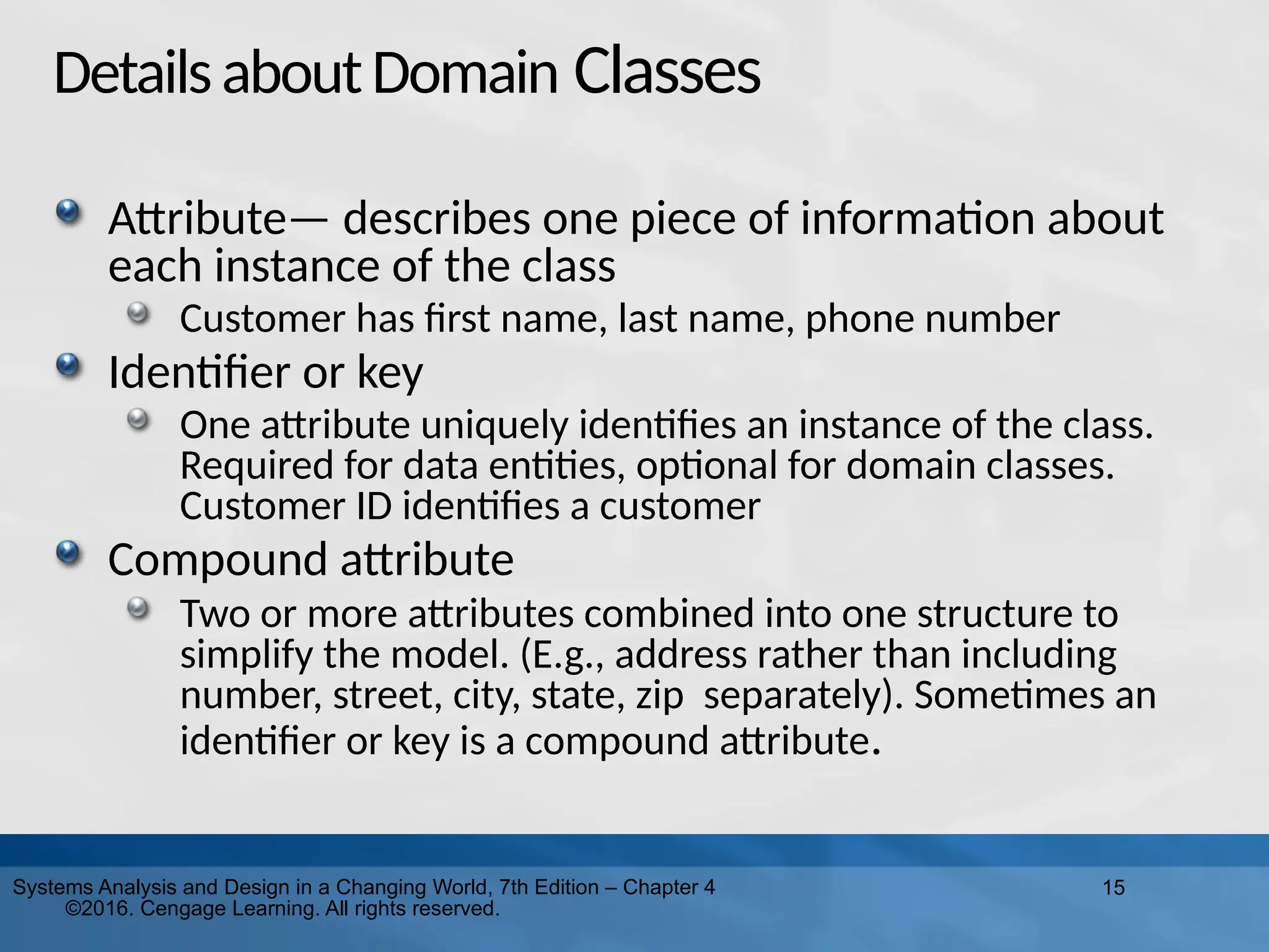
Design in a Changing World, 7th Edition – Chapter 4 ©2016. Cengage Learning. All rights reserved. DetailsaboutDomain Classes Attribute— describes one piece of information about each instance of the class Customer has first name, last name, phone number Identifier or key One attribute uniquely identifies an instance of the class. Required for data entities, optional for domain classes. Customer ID identifies a customer Compound attribute Two or more attributes combined into one structure to simplify the model. (E.g., address rather than including number, street, city, state, zip separately). Sometimes an identifier or key is a compound attribute.
16.
16 Systems Analysis and
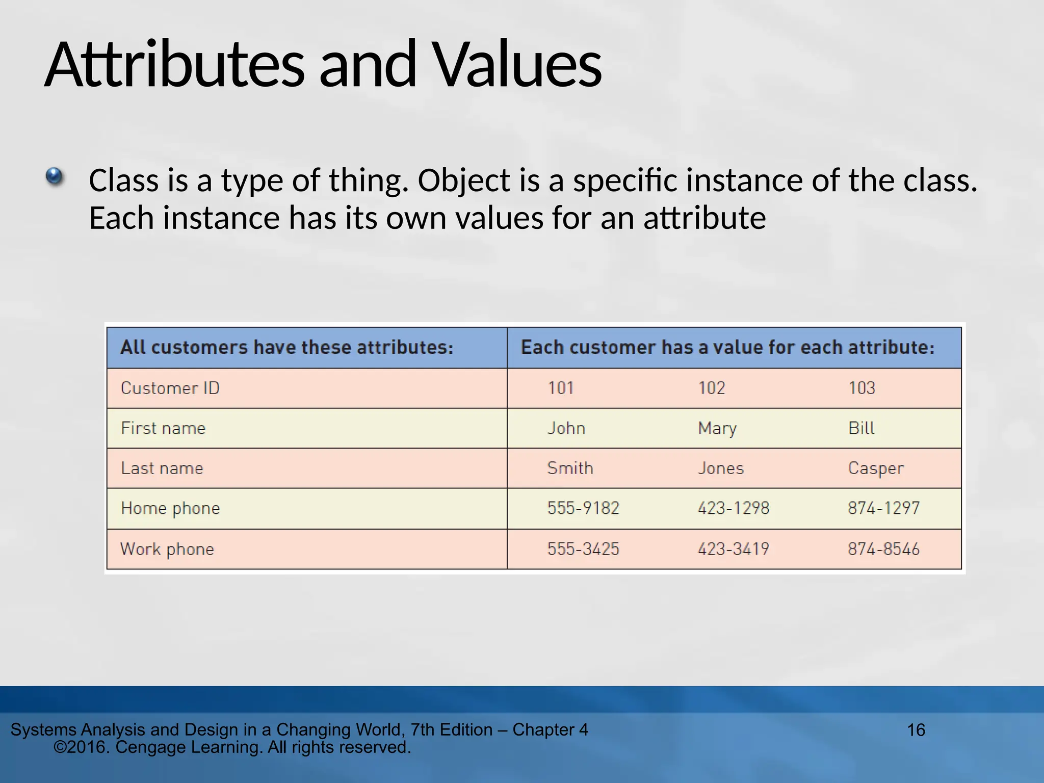
Design in a Changing World, 7th Edition – Chapter 4 ©2016. Cengage Learning. All rights reserved. Attributes and Values Class is a type of thing. Object is a specific instance of the class. Each instance has its own values for an attribute
17.
17 Systems Analysis and
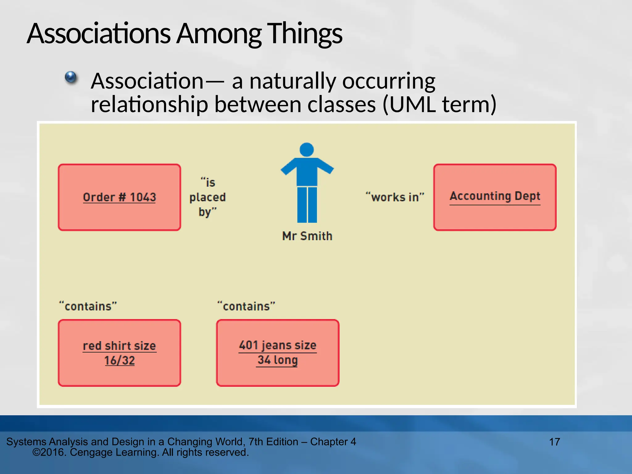
Design in a Changing World, 7th Edition – Chapter 4 ©2016. Cengage Learning. All rights reserved. AssociationsAmongThings Association— a naturally occurring relationship between classes (UML term)
18.
JusttoClarify… Called association on
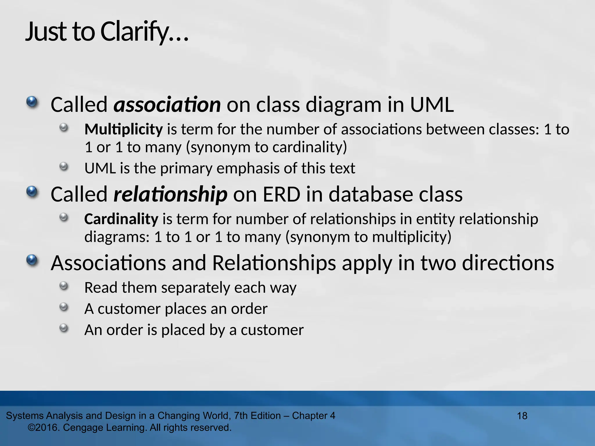
class diagram in UML Multiplicity is term for the number of associations between classes: 1 to 1 or 1 to many (synonym to cardinality) UML is the primary emphasis of this text Called relationship on ERD in database class Cardinality is term for number of relationships in entity relationship diagrams: 1 to 1 or 1 to many (synonym to multiplicity) Associations and Relationships apply in two directions Read them separately each way A customer places an order An order is placed by a customer 18 Systems Analysis and Design in a Changing World, 7th Edition – Chapter 4 ©2016. Cengage Learning. All rights reserved.
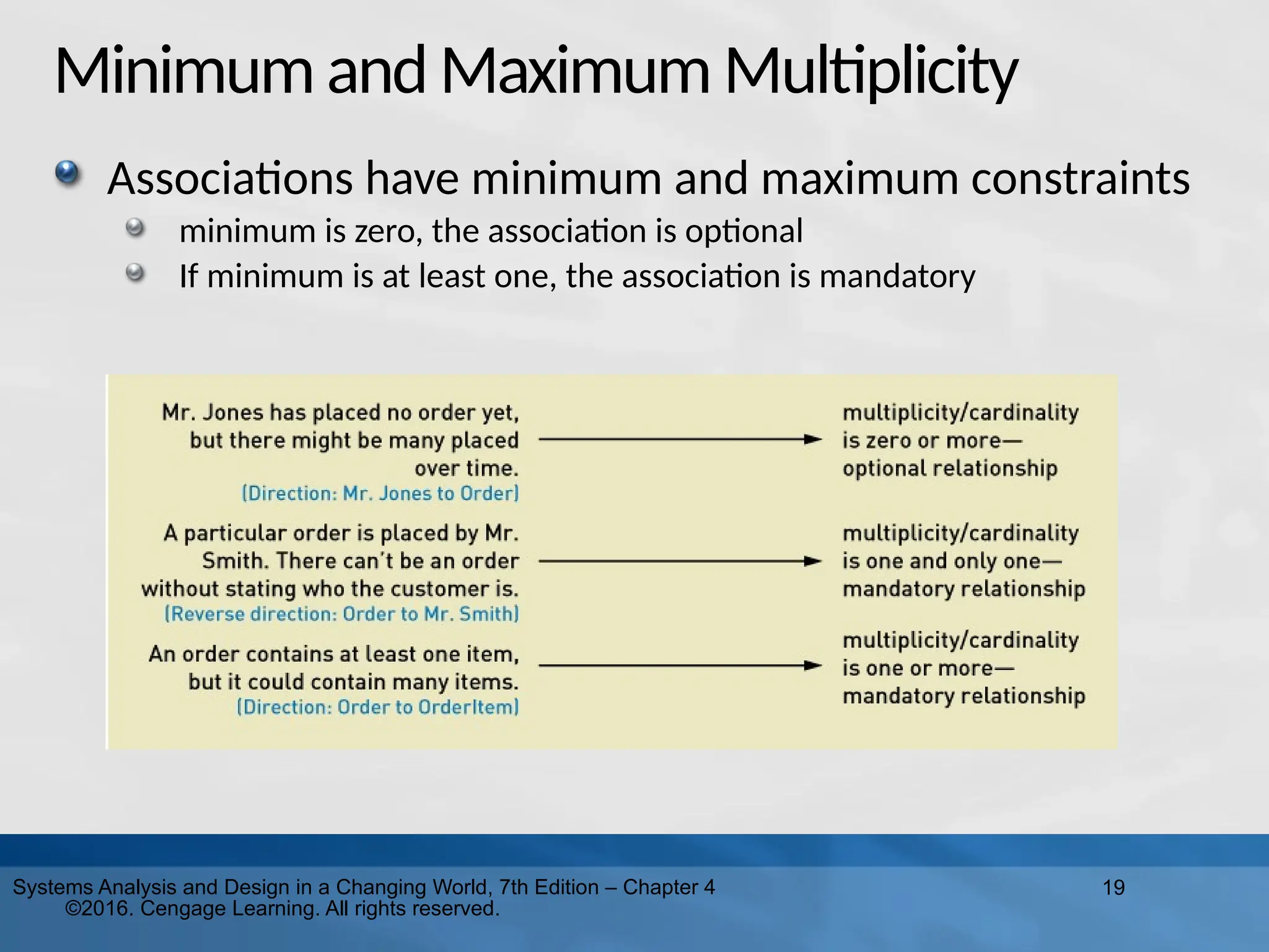
19.
19 Systems Analysis and
Design in a Changing World, 7th Edition – Chapter 4 ©2016. Cengage Learning. All rights reserved. MinimumandMaximumMultiplicity Associations have minimum and maximum constraints minimum is zero, the association is optional If minimum is at least one, the association is mandatory
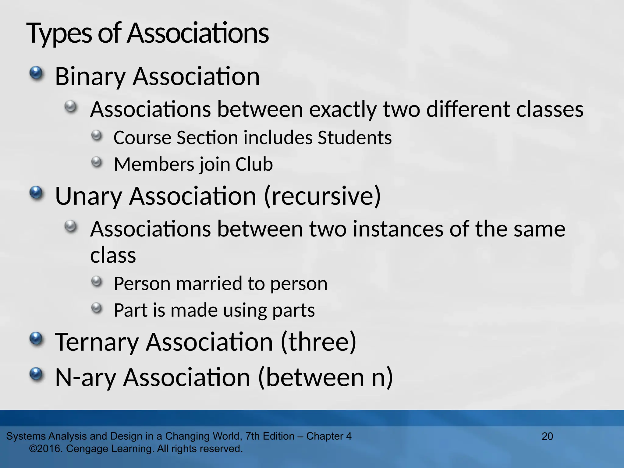
20.
TypesofAssociations Binary Association Associations between
exactly two different classes Course Section includes Students Members join Club Unary Association (recursive) Associations between two instances of the same class Person married to person Part is made using parts Ternary Association (three) N-ary Association (between n) 20 Systems Analysis and Design in a Changing World, 7th Edition – Chapter 4 ©2016. Cengage Learning. All rights reserved.
21.
Entity-RelationshipDiagrams ERD ERDs have been
used for many years to develop data models that are used in database development The term for “things” in ERD models is data entities ERD models are not UML models and do not use standard UML notation ERD models are not as expressive as UML models They do not model generalization/specialization well They do not model whole/part well 21 Systems Analysis and Design in a Changing World, 7th Edition – Chapter 4 ©2016. Cengage Learning. All rights reserved.
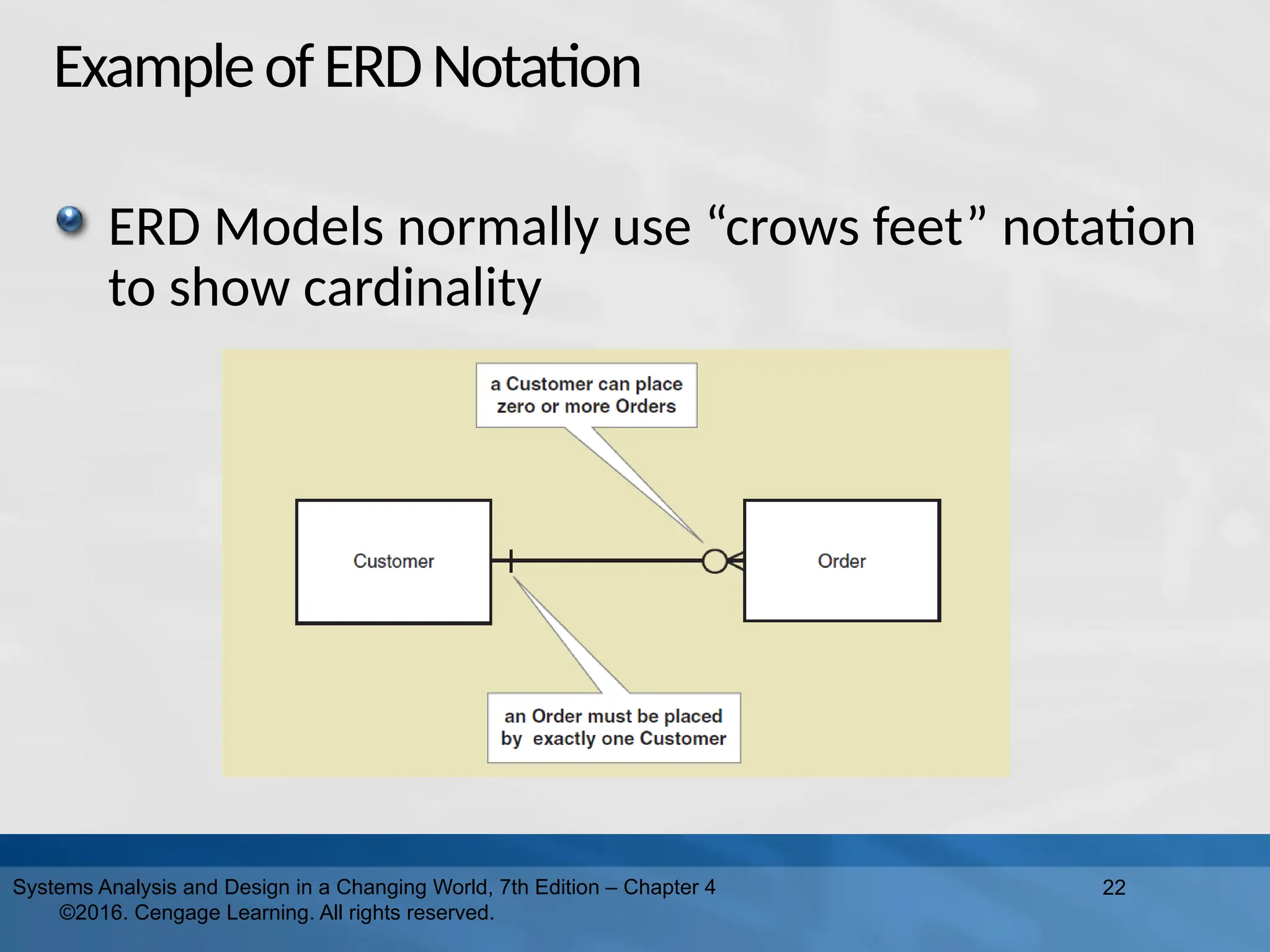
22.
ExampleofERDNotation ERD Models normally
use “crows feet” notation to show cardinality 22 Systems Analysis and Design in a Changing World, 7th Edition – Chapter 4 ©2016. Cengage Learning. All rights reserved.
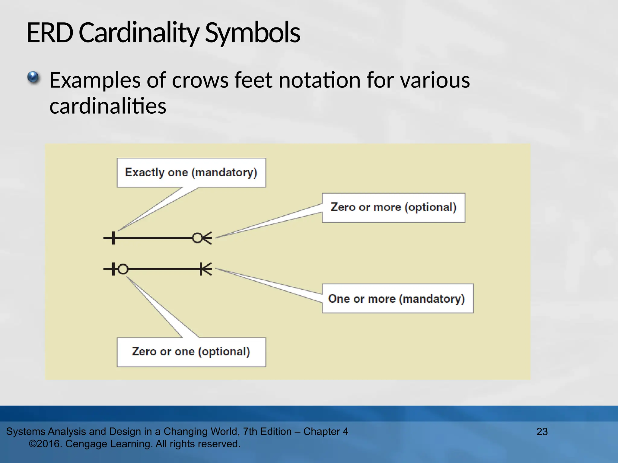
23.
ERDCardinalitySymbols Examples of crows
feet notation for various cardinalities 23 Systems Analysis and Design in a Changing World, 7th Edition – Chapter 4 ©2016. Cengage Learning. All rights reserved.
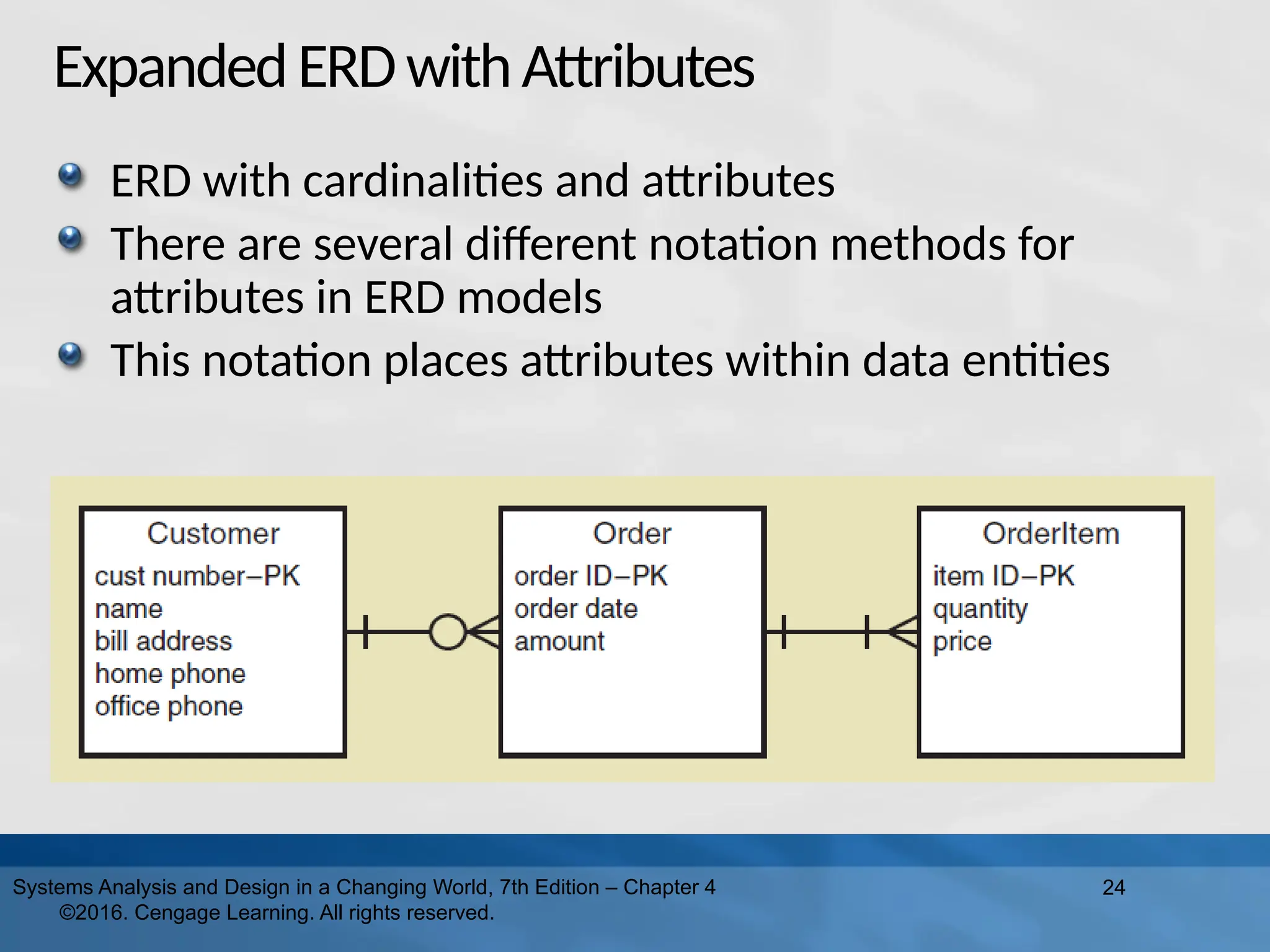
24.
ExpandedERDwithAttributes ERD with cardinalities
and attributes There are several different notation methods for attributes in ERD models This notation places attributes within data entities 24 Systems Analysis and Design in a Changing World, 7th Edition – Chapter 4 ©2016. Cengage Learning. All rights reserved.
25.
25 Systems Analysis and
Design in a Changing World, 7th Edition – Chapter 4 ©2016. Cengage Learning. All rights reserved. Semantic Net A semantic net is a graphical representation of an individual data entity and its relationship with other individual entities It is often used to help understand and then develop an ERD model
26.
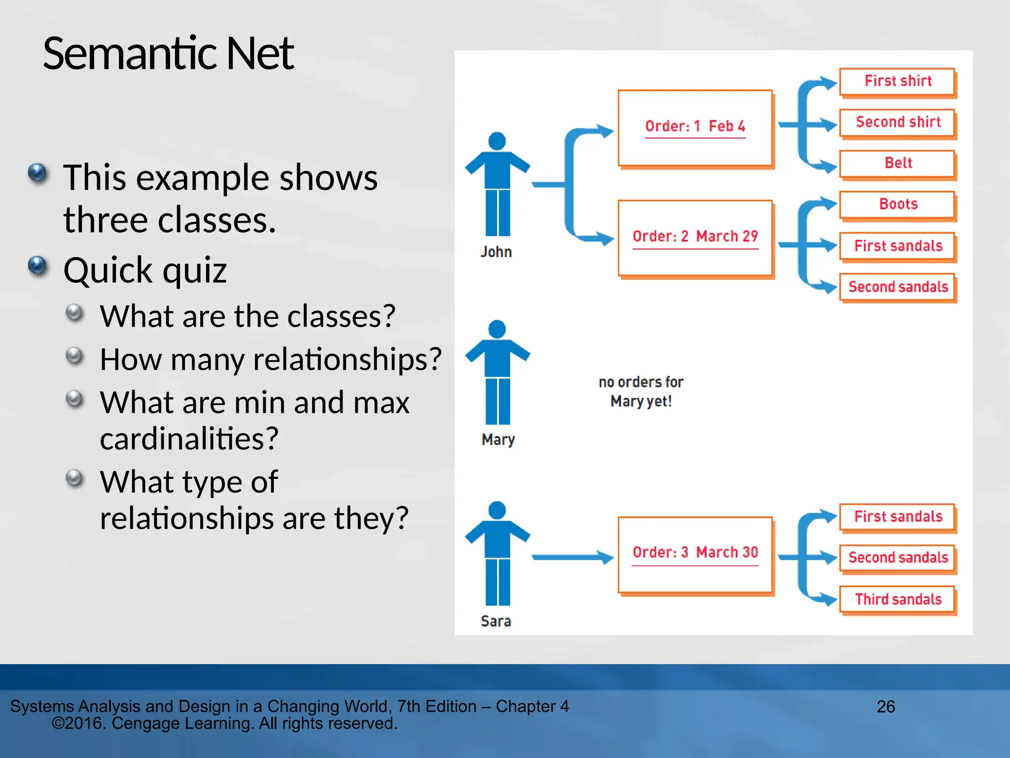
26 Systems Analysis and
Design in a Changing World, 7th Edition – Chapter 4 ©2016. Cengage Learning. All rights reserved. SemanticNet This example shows three classes. Quick quiz What are the classes? How many relationships? What are min and max cardinalities? What type of relationships are they?
27.
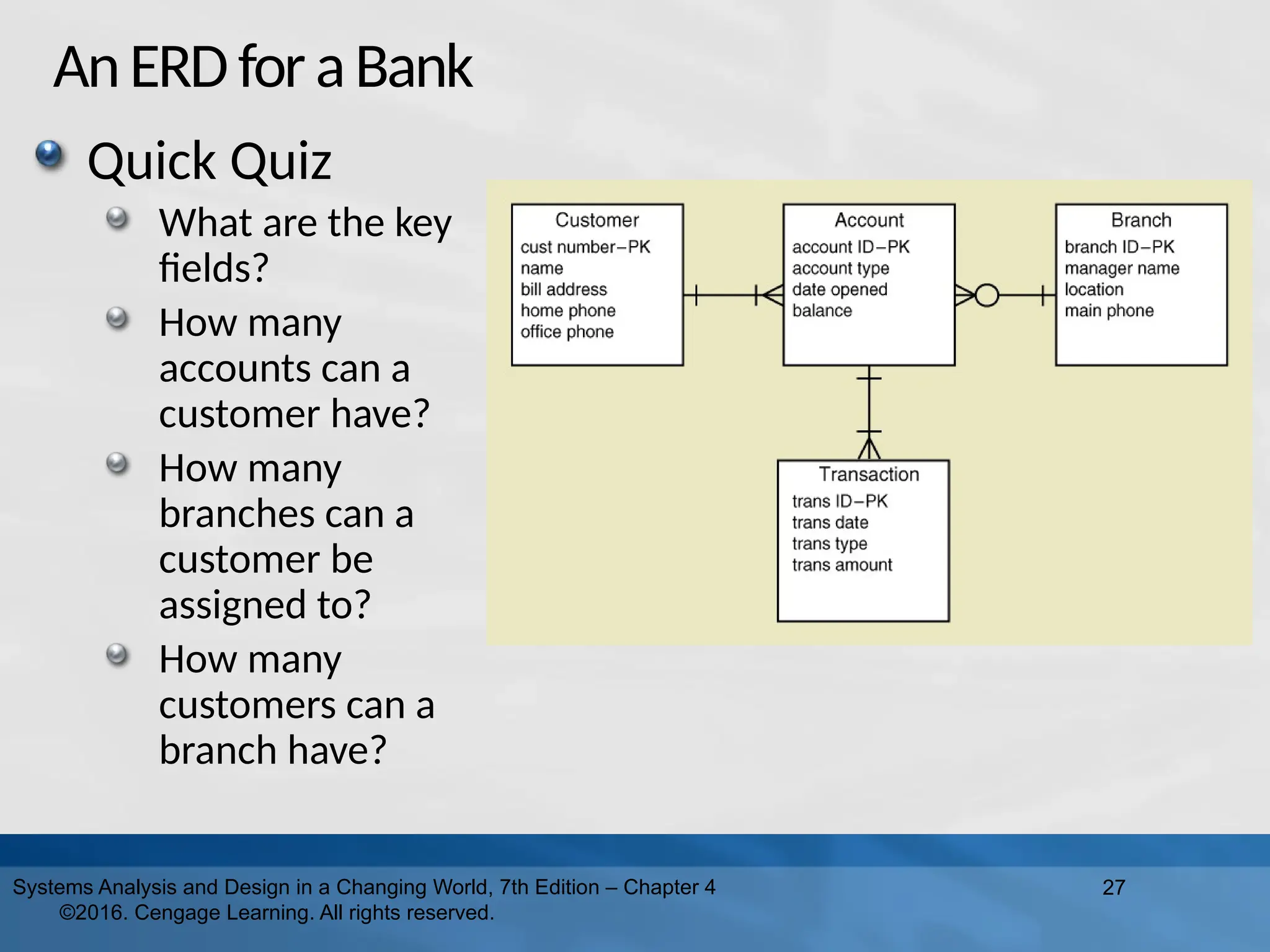
AnERDforaBank 27 Systems Analysis and
Design in a Changing World, 7th Edition – Chapter 4 ©2016. Cengage Learning. All rights reserved. Quick Quiz What are the key fields? How many accounts can a customer have? How many branches can a customer be assigned to? How many customers can a branch have?
28.
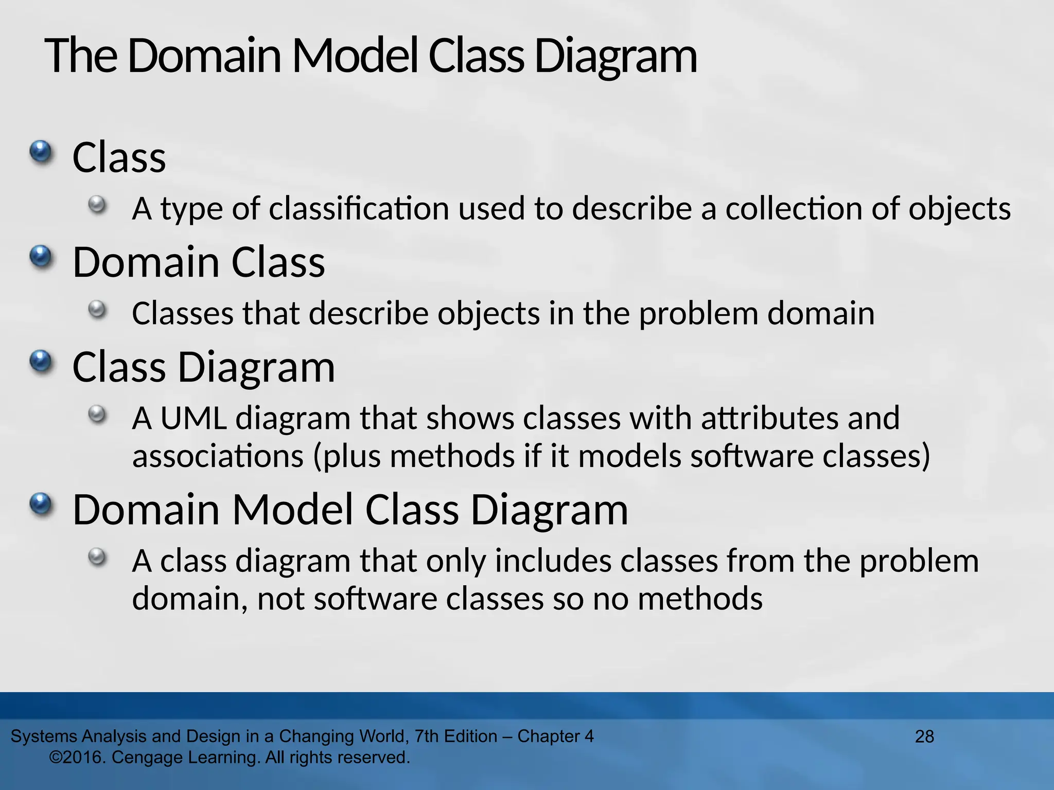
TheDomainModelClassDiagram Class A type of
classification used to describe a collection of objects Domain Class Classes that describe objects in the problem domain Class Diagram A UML diagram that shows classes with attributes and associations (plus methods if it models software classes) Domain Model Class Diagram A class diagram that only includes classes from the problem domain, not software classes so no methods 28 Systems Analysis and Design in a Changing World, 7th Edition – Chapter 4 ©2016. Cengage Learning. All rights reserved.
29.
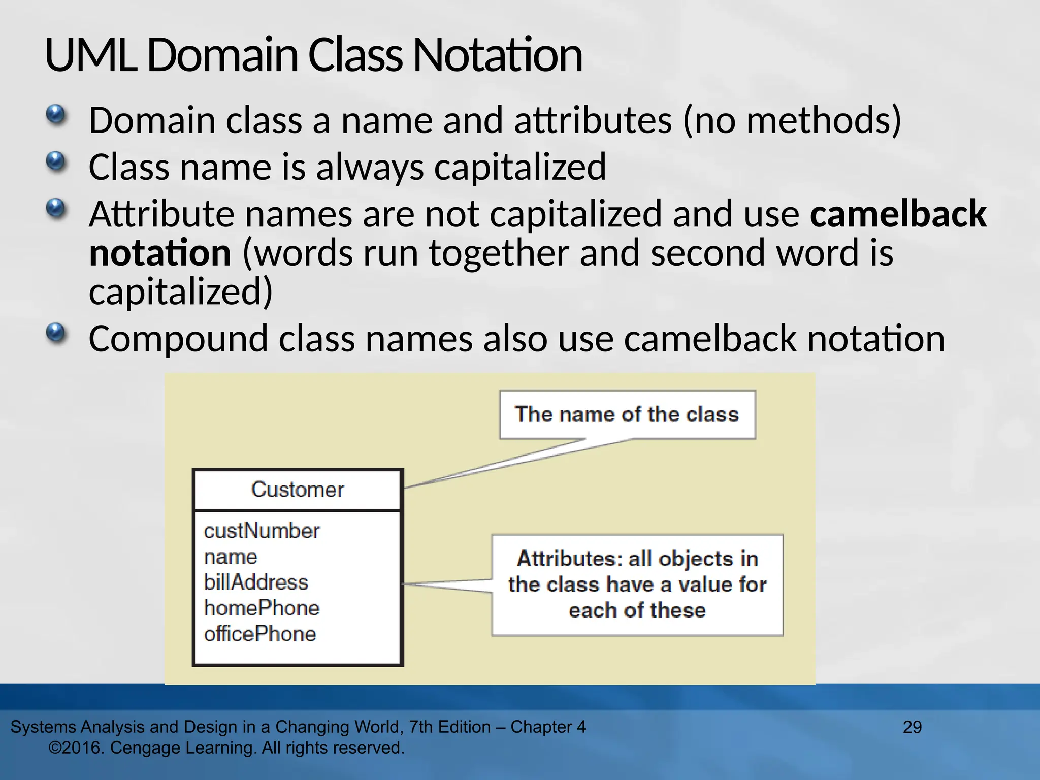
UMLDomainClassNotation Domain class a
name and attributes (no methods) Class name is always capitalized Attribute names are not capitalized and use camelback notation (words run together and second word is capitalized) Compound class names also use camelback notation 29 Systems Analysis and Design in a Changing World, 7th Edition – Chapter 4 ©2016. Cengage Learning. All rights reserved.
30.
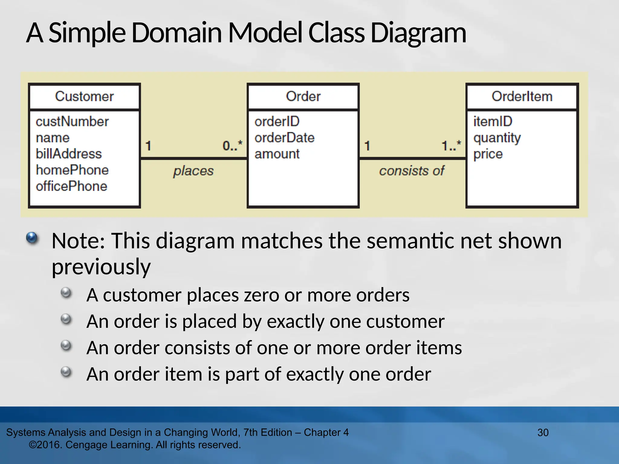
ASimpleDomainModelClassDiagram Note: This diagram
matches the semantic net shown previously A customer places zero or more orders An order is placed by exactly one customer An order consists of one or more order items An order item is part of exactly one order 30 Systems Analysis and Design in a Changing World, 7th Edition – Chapter 4 ©2016. Cengage Learning. All rights reserved.
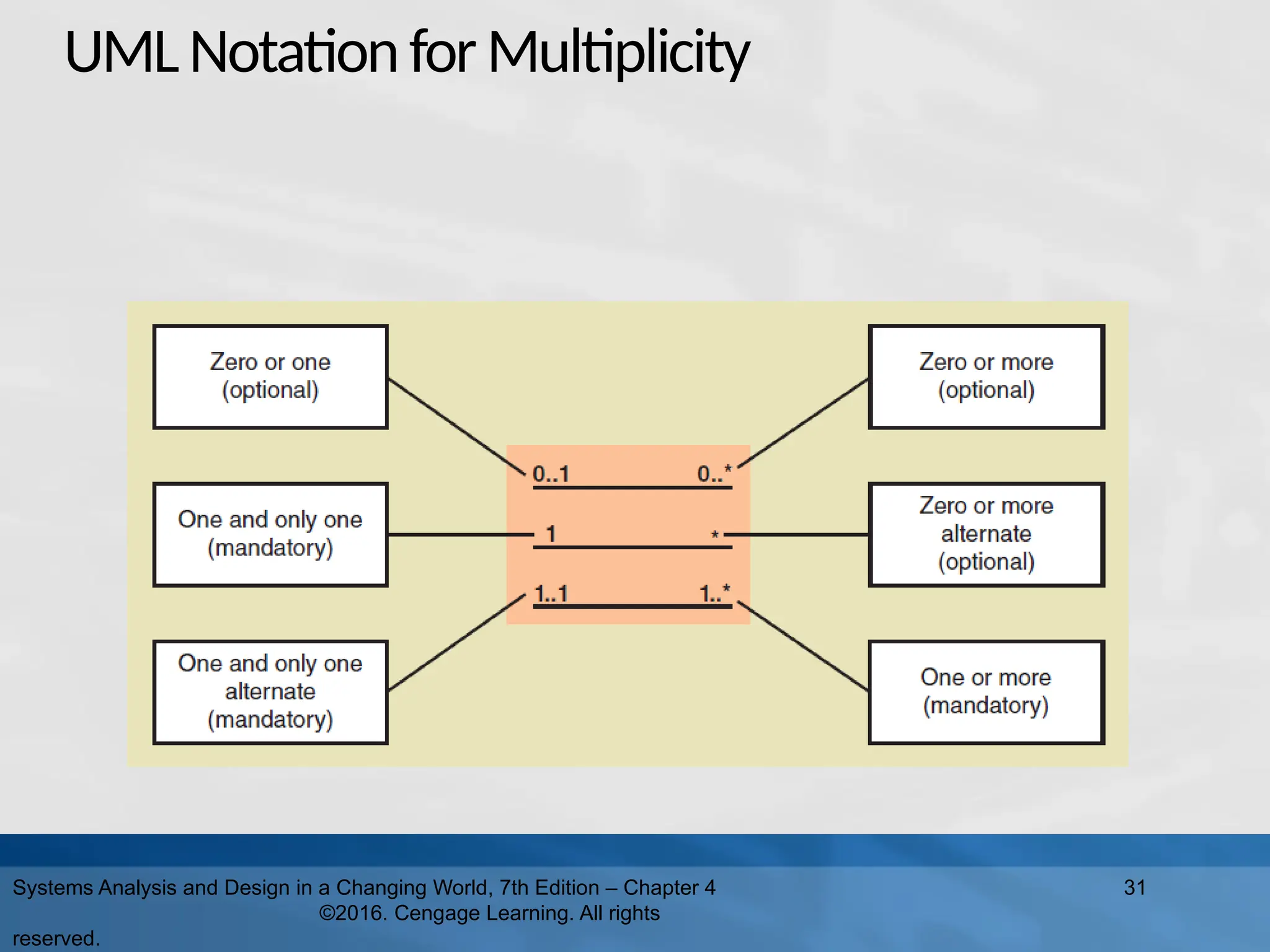
31.
UMLNotationforMultiplicity Systems Analysis and
Design in a Changing World, 7th Edition – Chapter 4 ©2016. Cengage Learning. All rights reserved. 31
32.
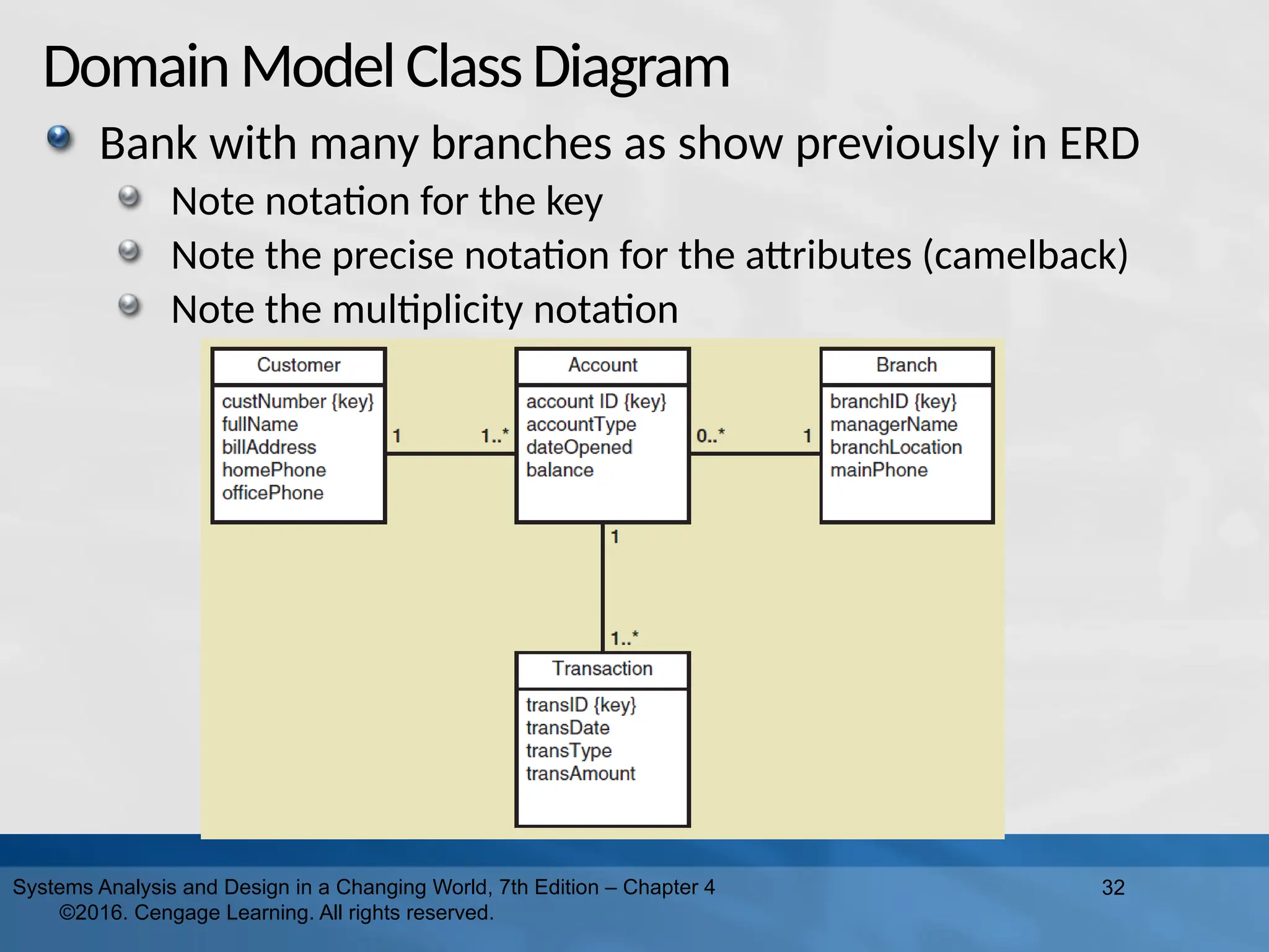
DomainModelClassDiagram Bank with many
branches as show previously in ERD Note notation for the key Note the precise notation for the attributes (camelback) Note the multiplicity notation 32 Systems Analysis and Design in a Changing World, 7th Edition – Chapter 4 ©2016. Cengage Learning. All rights reserved.
33.
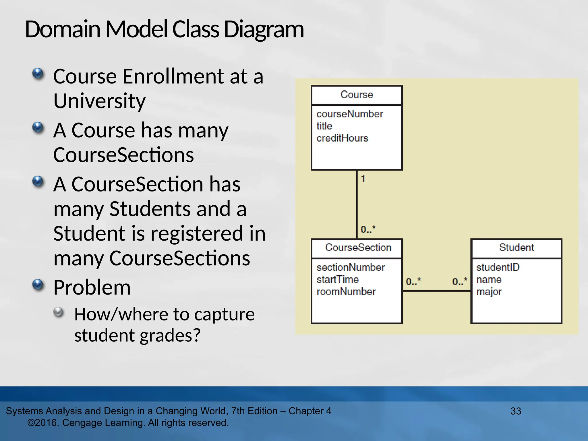
DomainModelClassDiagram Course Enrollment at
a University A Course has many CourseSections A CourseSection has many Students and a Student is registered in many CourseSections Problem How/where to capture student grades? 33 Systems Analysis and Design in a Changing World, 7th Edition – Chapter 4 ©2016. Cengage Learning. All rights reserved.
34.
34 Systems Analysis and
Design in a Changing World, 7th Edition – Chapter 4 ©2016. Cengage Learning. All rights reserved. Chapter Outline (Cont.) – PART II “Things” in the Problem Domain The Entity-Relationship Diagram The Domain Model Class Diagram The State Machine Diagram – Identifying Object Behavior
35.
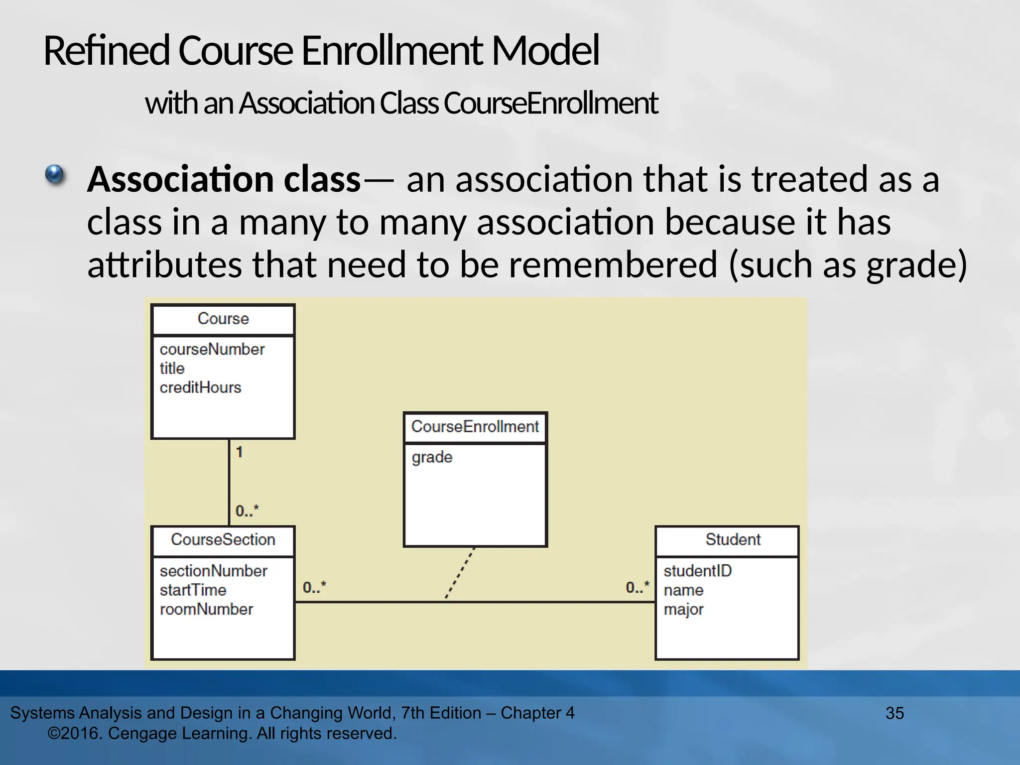
RefinedCourseEnrollmentModel withanAssociationClassCourseEnrollment Association class— an
association that is treated as a class in a many to many association because it has attributes that need to be remembered (such as grade) 35 Systems Analysis and Design in a Changing World, 7th Edition – Chapter 4 ©2016. Cengage Learning. All rights reserved.
36.
36 Systems Analysis and
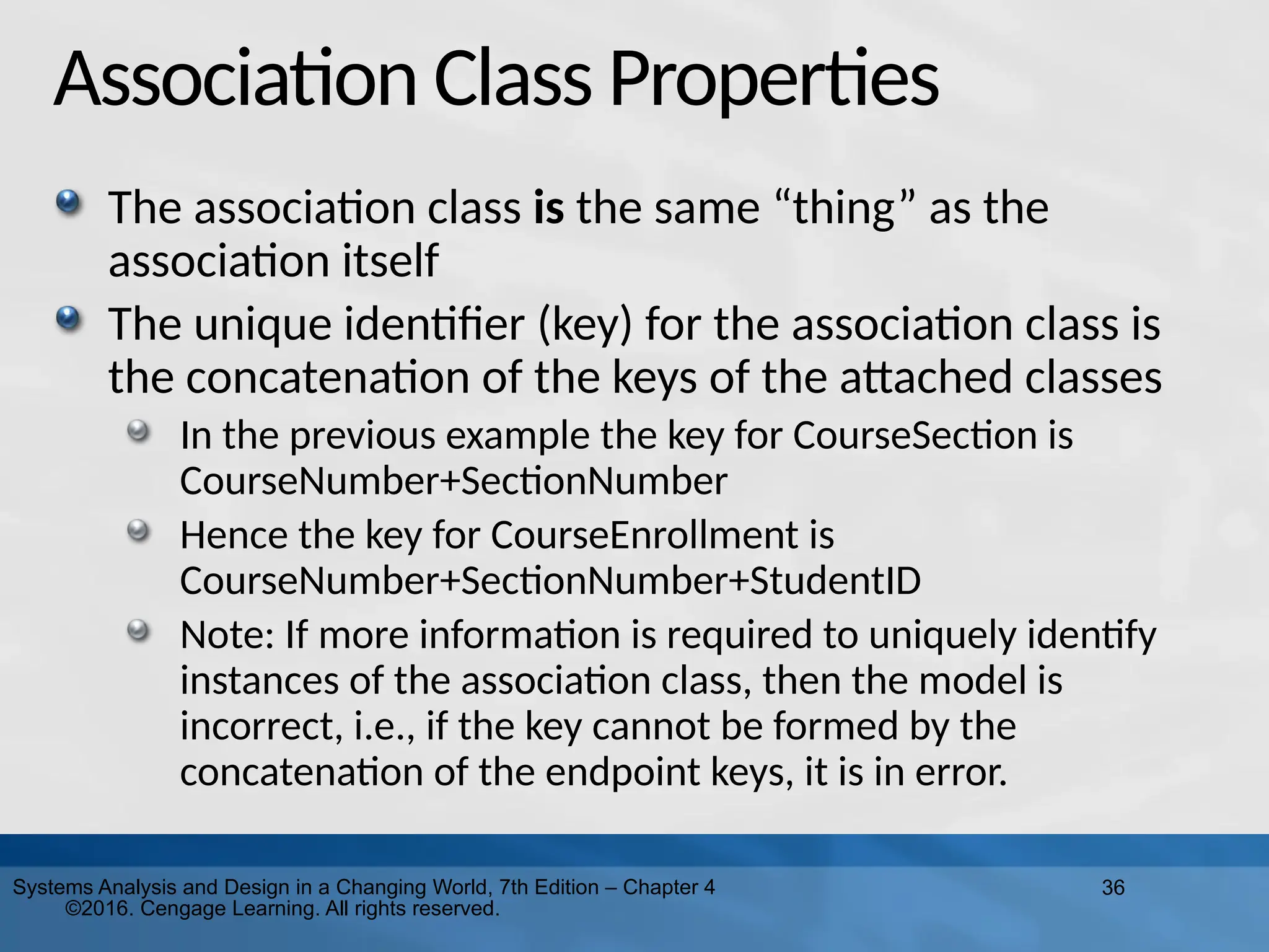
Design in a Changing World, 7th Edition – Chapter 4 ©2016. Cengage Learning. All rights reserved. Association Class Properties The association class is the same “thing” as the association itself The unique identifier (key) for the association class is the concatenation of the keys of the attached classes In the previous example the key for CourseSection is CourseNumber+SectionNumber Hence the key for CourseEnrollment is CourseNumber+SectionNumber+StudentID Note: If more information is required to uniquely identify instances of the association class, then the model is incorrect, i.e., if the key cannot be formed by the concatenation of the endpoint keys, it is in error.
37.
37 Systems Analysis and
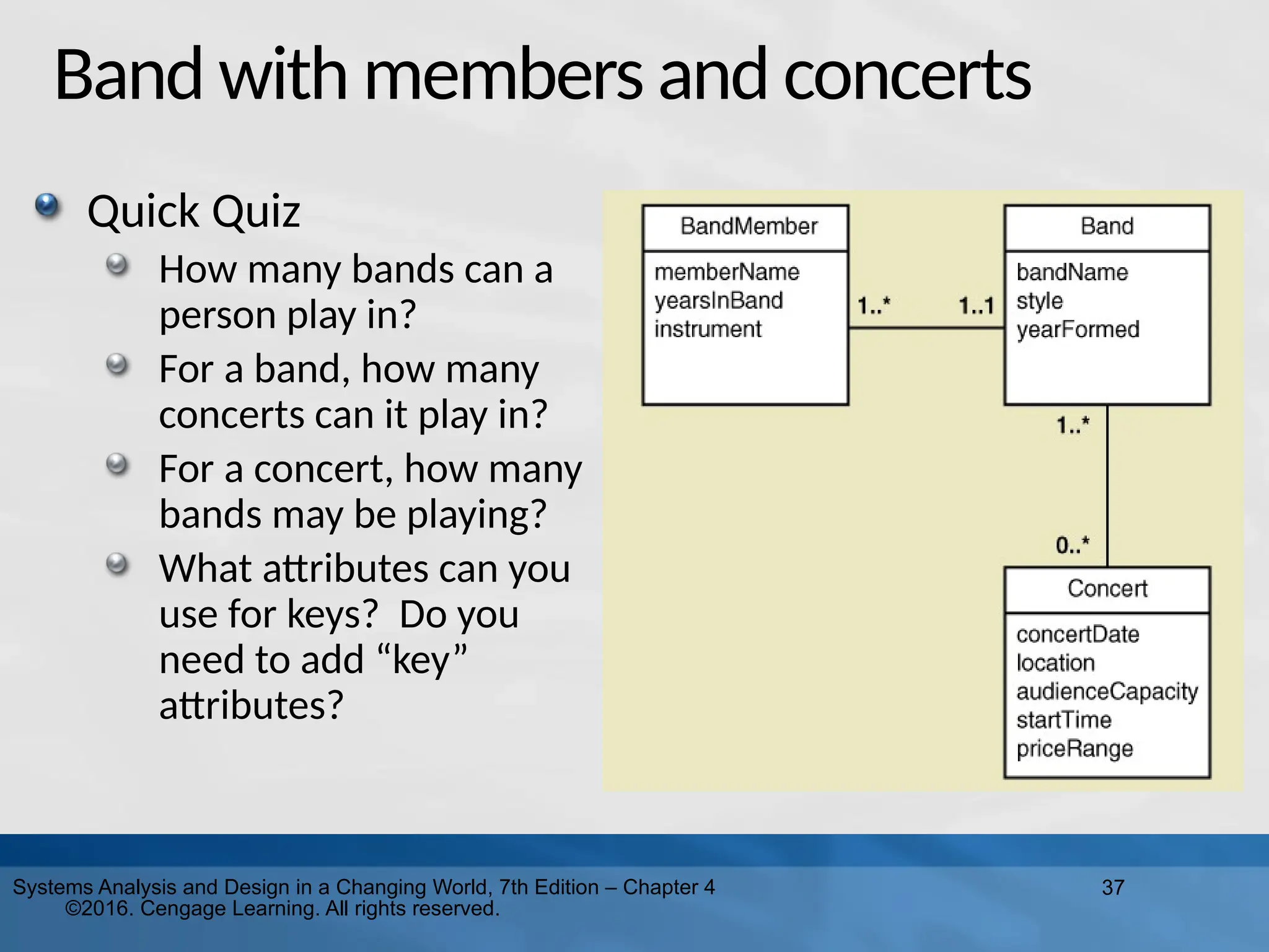
Design in a Changing World, 7th Edition – Chapter 4 ©2016. Cengage Learning. All rights reserved. Band with members and concerts Quick Quiz How many bands can a person play in? For a band, how many concerts can it play in? For a concert, how many bands may be playing? What attributes can you use for keys? Do you need to add “key” attributes?
38.
38 Systems Analysis and
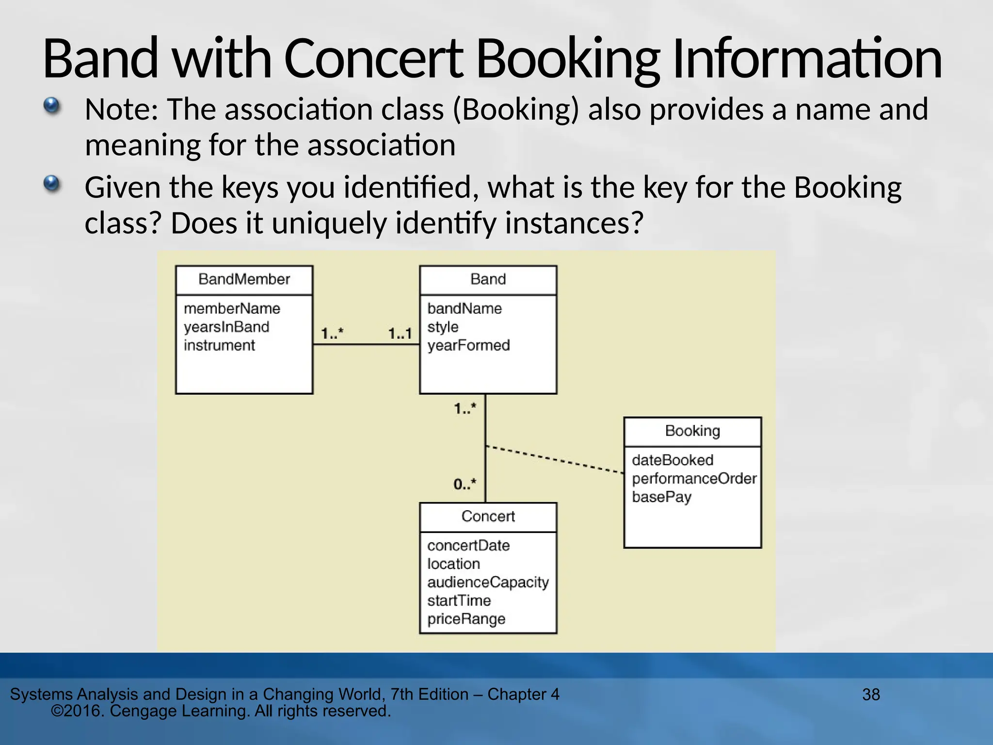
Design in a Changing World, 7th Edition – Chapter 4 ©2016. Cengage Learning. All rights reserved. Band with Concert Booking Information Note: The association class (Booking) also provides a name and meaning for the association Given the keys you identified, what is the key for the Booking class? Does it uniquely identify instances?
39.
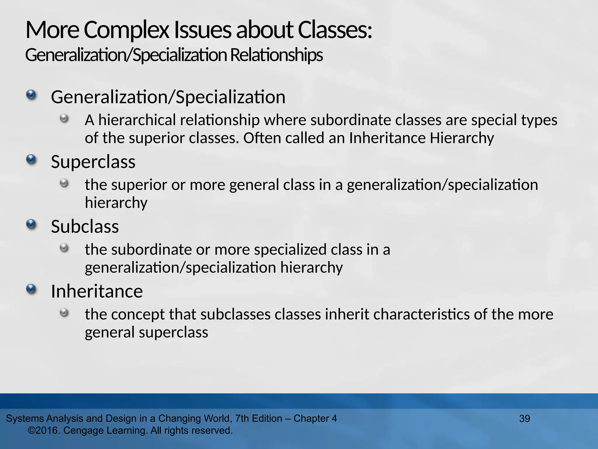
MoreComplexIssuesaboutClasses: Generalization/SpecializationRelationships Generalization/Specialization A hierarchical relationship
where subordinate classes are special types of the superior classes. Often called an Inheritance Hierarchy Superclass the superior or more general class in a generalization/specialization hierarchy Subclass the subordinate or more specialized class in a generalization/specialization hierarchy Inheritance the concept that subclasses classes inherit characteristics of the more general superclass 39 Systems Analysis and Design in a Changing World, 7th Edition – Chapter 4 ©2016. Cengage Learning. All rights reserved.
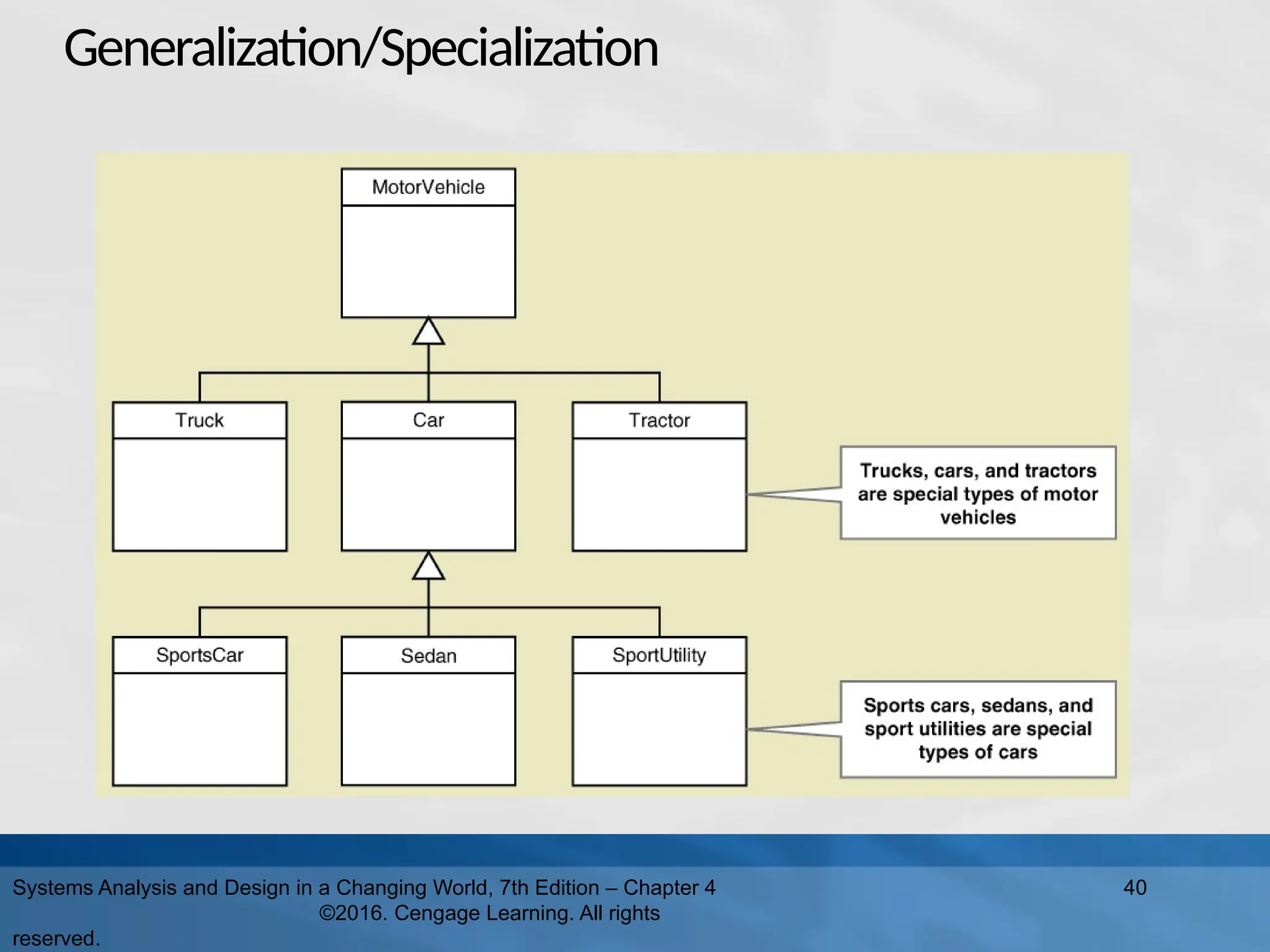
40.
Generalization/Specialization Systems Analysis and
Design in a Changing World, 7th Edition – Chapter 4 ©2016. Cengage Learning. All rights reserved. 40
41.
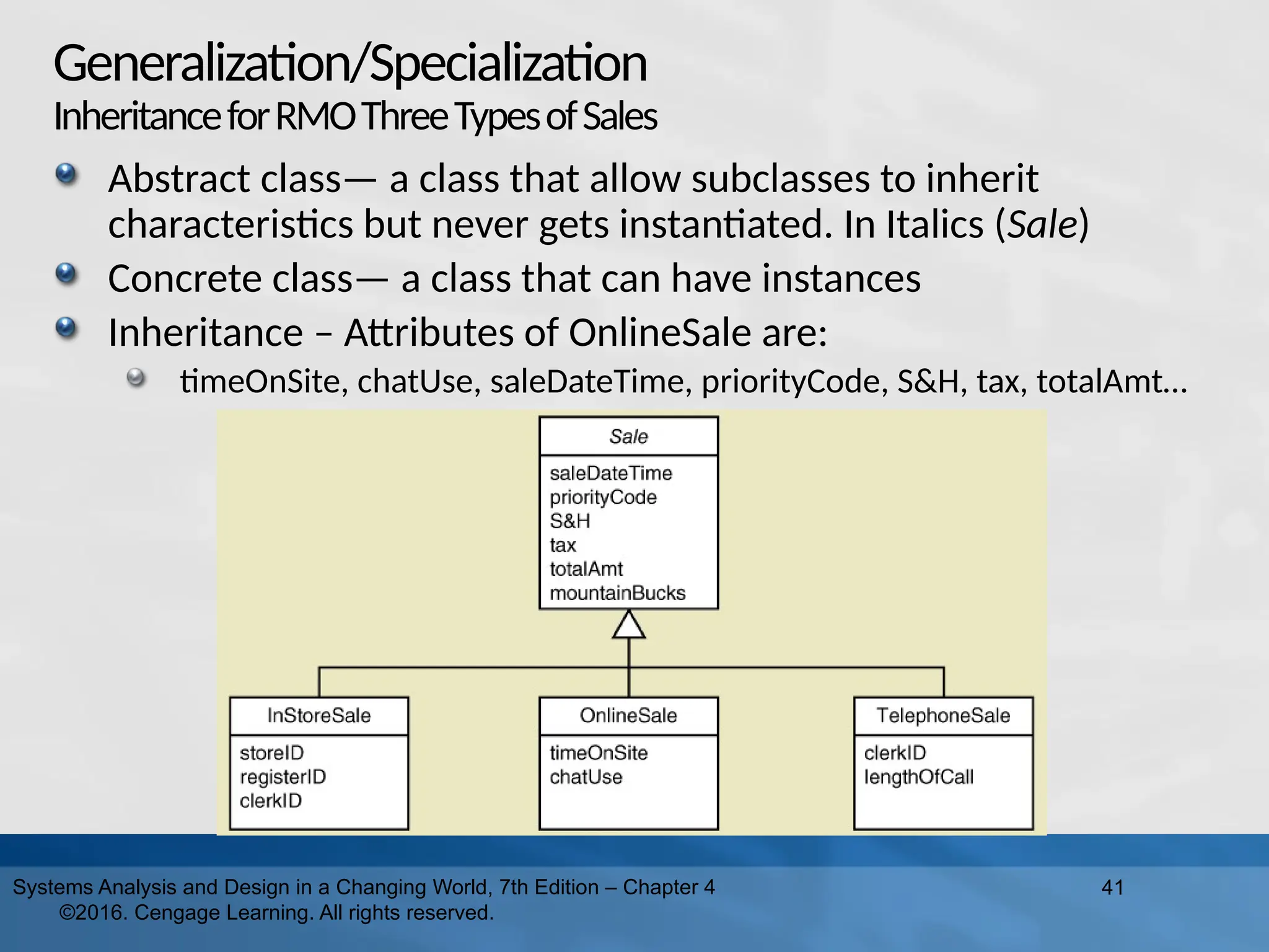
Generalization/Specialization InheritanceforRMOThreeTypesofSales Abstract class— a
class that allow subclasses to inherit characteristics but never gets instantiated. In Italics (Sale) Concrete class— a class that can have instances Inheritance – Attributes of OnlineSale are: timeOnSite, chatUse, saleDateTime, priorityCode, S&H, tax, totalAmt… 41 Systems Analysis and Design in a Changing World, 7th Edition – Chapter 4 ©2016. Cengage Learning. All rights reserved.
42.
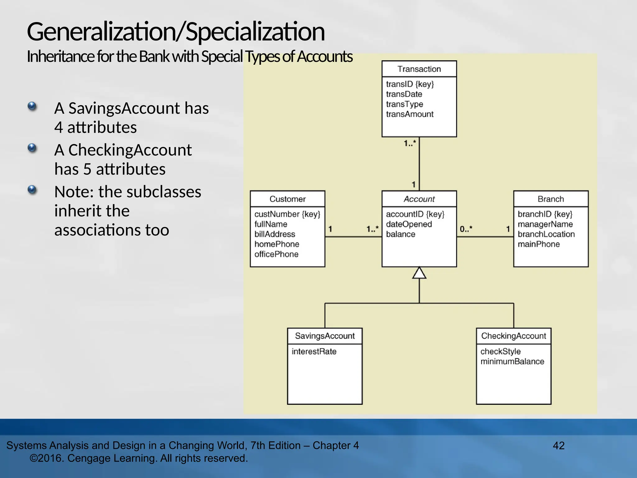
A SavingsAccount has 4
attributes A CheckingAccount has 5 attributes Note: the subclasses inherit the associations too 42 Systems Analysis and Design in a Changing World, 7th Edition – Chapter 4 ©2016. Cengage Learning. All rights reserved. Generalization/Specialization InheritancefortheBankwithSpecialTypesofAccounts
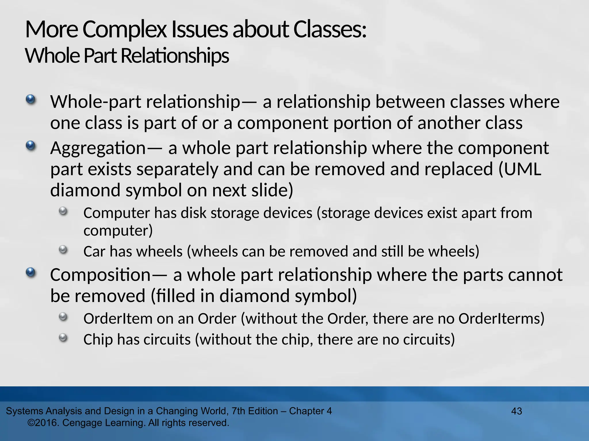
43.
MoreComplexIssuesaboutClasses: WholePartRelationships Whole-part relationship— a
relationship between classes where one class is part of or a component portion of another class Aggregation— a whole part relationship where the component part exists separately and can be removed and replaced (UML diamond symbol on next slide) Computer has disk storage devices (storage devices exist apart from computer) Car has wheels (wheels can be removed and still be wheels) Composition— a whole part relationship where the parts cannot be removed (filled in diamond symbol) OrderItem on an Order (without the Order, there are no OrderIterms) Chip has circuits (without the chip, there are no circuits) 43 Systems Analysis and Design in a Changing World, 7th Edition – Chapter 4 ©2016. Cengage Learning. All rights reserved.
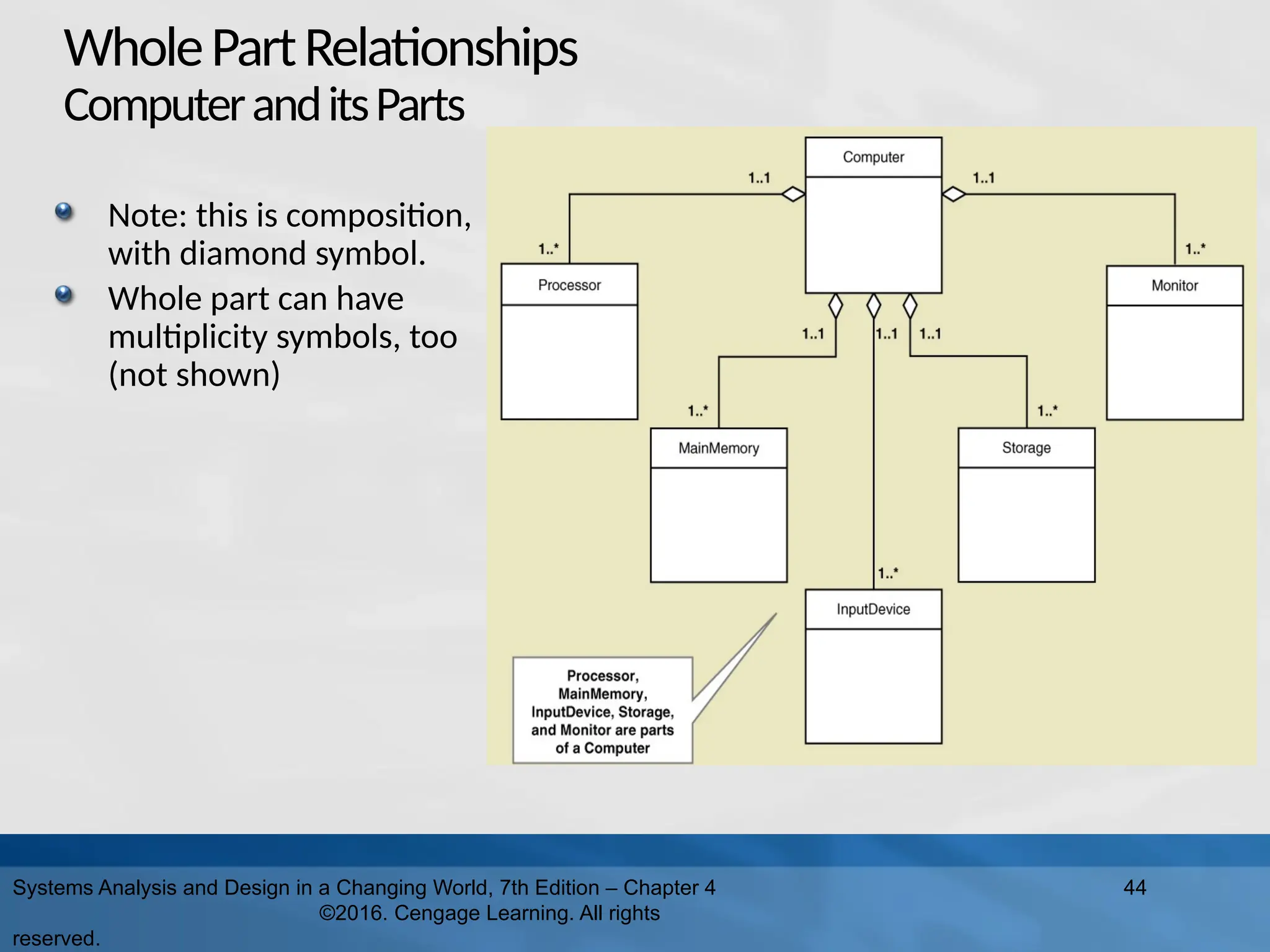
44.
WholePartRelationships ComputeranditsParts Systems Analysis and
Design in a Changing World, 7th Edition – Chapter 4 ©2016. Cengage Learning. All rights reserved. 44 Note: this is composition, with diamond symbol. Whole part can have multiplicity symbols, too (not shown)
45.
MoreonUMLRelationships There are actually
three types of relationships in class diagrams Association Relationships These are associations discussed previously, just like ERD relationships Whole Part Relationships One class is a component or part of another class Generalizations/Specialization Relationships Inheritance Try not to confuse relationship with association 45 Systems Analysis and Design in a Changing World, 7th Edition – Chapter 4 ©2016. Cengage Learning. All rights reserved.
46.
RMOCSMSProject DomainModelClassDiagrams There are several
ways to create the domain model class diagram for a project RMO CSMS has 27 domain classes overall Can create one domain model class diagram per subsystem for those working on a subsystem Can create one overall domain model class diagram to provide an overview of the whole system Usually in early iterations, an initial draft of the domain model class diagram is completed and kept up to date. It is used to guide development. 46 Systems Analysis and Design in a Changing World, 7th Edition – Chapter 4 ©2016. Cengage Learning. All rights reserved.
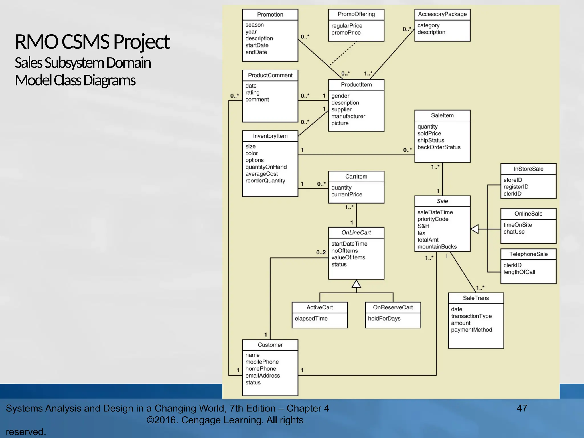
47.
RMOCSMSProject SalesSubsystemDomain ModelClassDiagrams Systems Analysis and
Design in a Changing World, 7th Edition – Chapter 4 ©2016. Cengage Learning. All rights reserved. 47
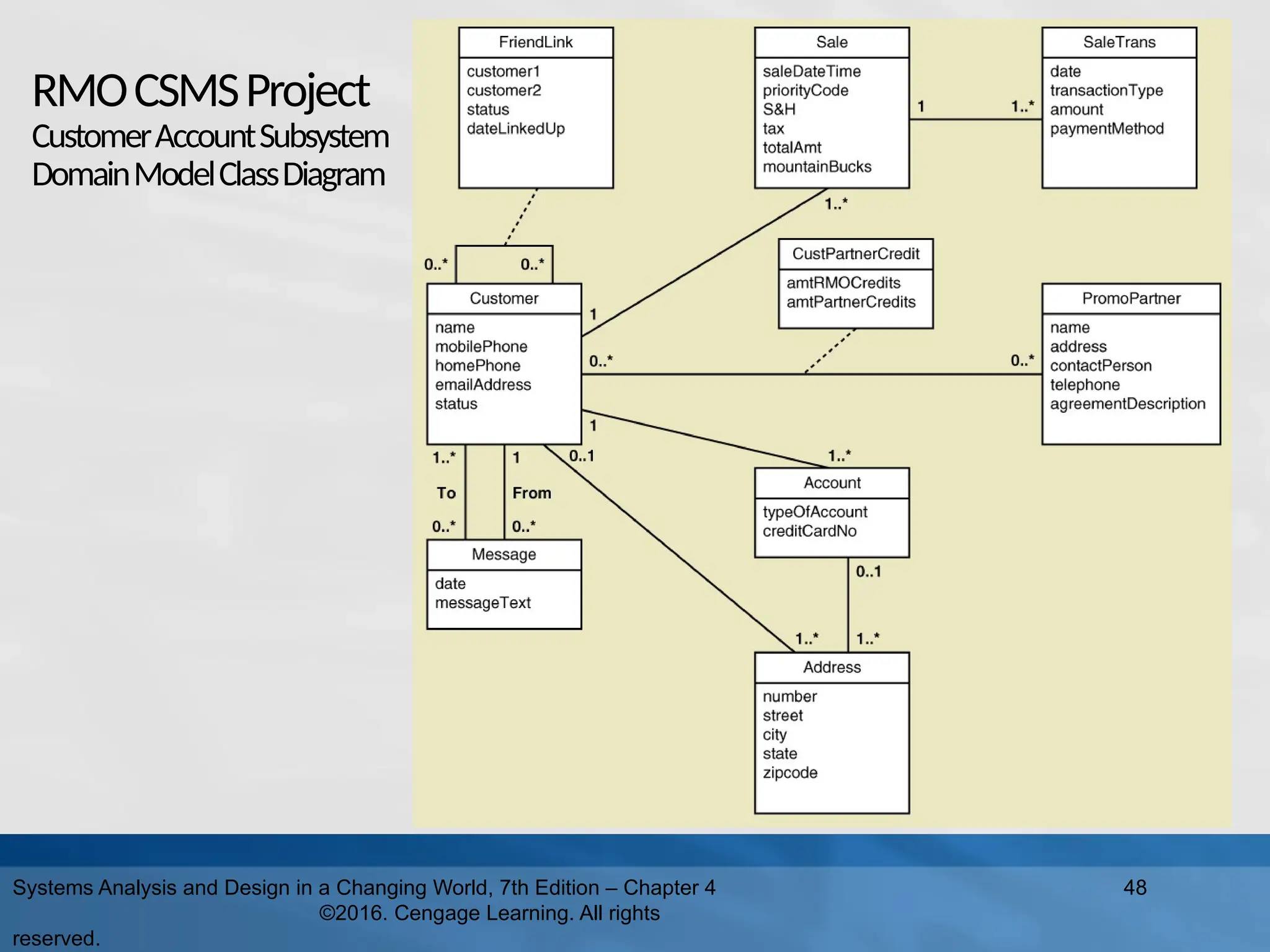
48.
RMOCSMSProject CustomerAccountSubsystem DomainModelClassDiagram Systems Analysis and
Design in a Changing World, 7th Edition – Chapter 4 ©2016. Cengage Learning. All rights reserved. 48
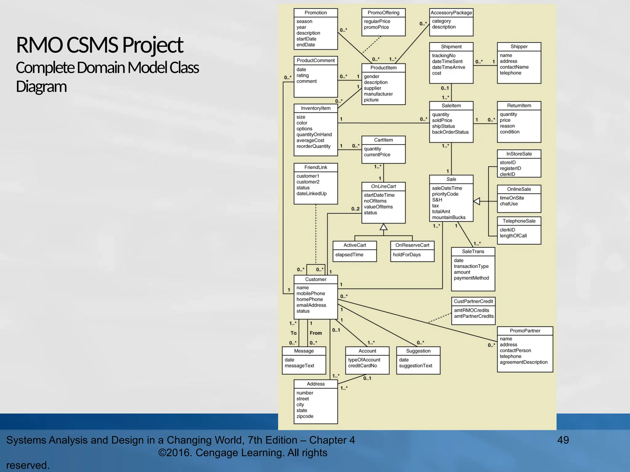
49.
RMOCSMSProject CompleteDomainModelClass Diagram Systems Analysis and
Design in a Changing World, 7th Edition – Chapter 4 ©2016. Cengage Learning. All rights reserved. 49
50.
RMOCSMSProject DomainModelClassDiagrams Given the complete
RMO CSMS Domain Model Class Diagram and Sales and Customer Account subsystem examples: Try completing the Order Fulfilment Subsystem Domain Model Class Diagram Try Completing the Marketing Subsystem Domain Model Class Diagram Try Completing the Reporting Subsystem Domain Model Class Diagram Review the use cases from Chapter 3 and decide what classes and associations from the complete model are required for each subsystem Classes and associations might be duplicated in more than one subsystem model 50 Systems Analysis and Design in a Changing World, 7th Edition – Chapter 4 ©2016. Cengage Learning. All rights reserved.
51.
51 Systems Analysis and
Design in a Changing World, 7th Edition – Chapter 4 ©2016. Cengage Learning. All rights reserved. ObjectBehavior– StateMachineDiagram Each class has objects that may have status conditions or “states” Object behavior consists of the various states and the movement between these states State – a condition during an object’s life when it satisfies some criterion, performs an action, or waits for an event Transition – the movement of an object from one state to another
52.
52 Systems Analysis and
Design in a Changing World, 7th Edition – Chapter 4 ©2016. Cengage Learning. All rights reserved. State Machine Diagram State Machine Diagram – a diagram which shows the life of an object in states and transitions Origin state – the original state of an object before it begins a transition Destination state – the state to which an object moves after completing a transition pseudostate – the starting point in a state machine diagram. Noted by a black circle. action-expression – some activity that must be completed as part of a transition guard-condition – a true/false test to see whether a transition can fire
53.
53 Systems Analysis and
Design in a Changing World, 7th Edition – Chapter 4 ©2016. Cengage Learning. All rights reserved. State Machine for a Printer Syntax of transition statement transition-name (parameters, …) [guard-condition] / action-expression
54.
54 Systems Analysis and
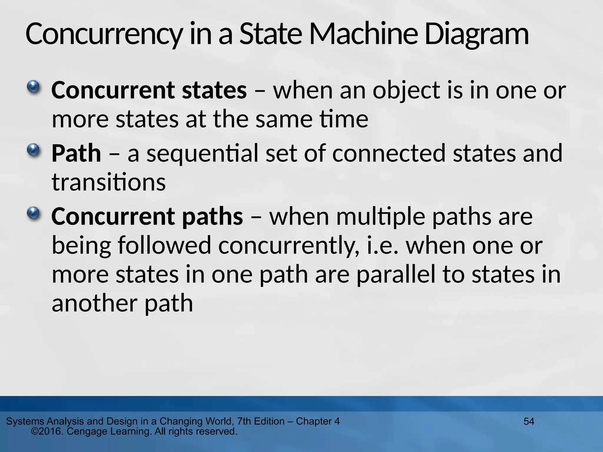
Design in a Changing World, 7th Edition – Chapter 4 ©2016. Cengage Learning. All rights reserved. Concurrency inaState MachineDiagram Concurrent states – when an object is in one or more states at the same time Path – a sequential set of connected states and transitions Concurrent paths – when multiple paths are being followed concurrently, i.e. when one or more states in one path are parallel to states in another path
55.
55 Systems Analysis and
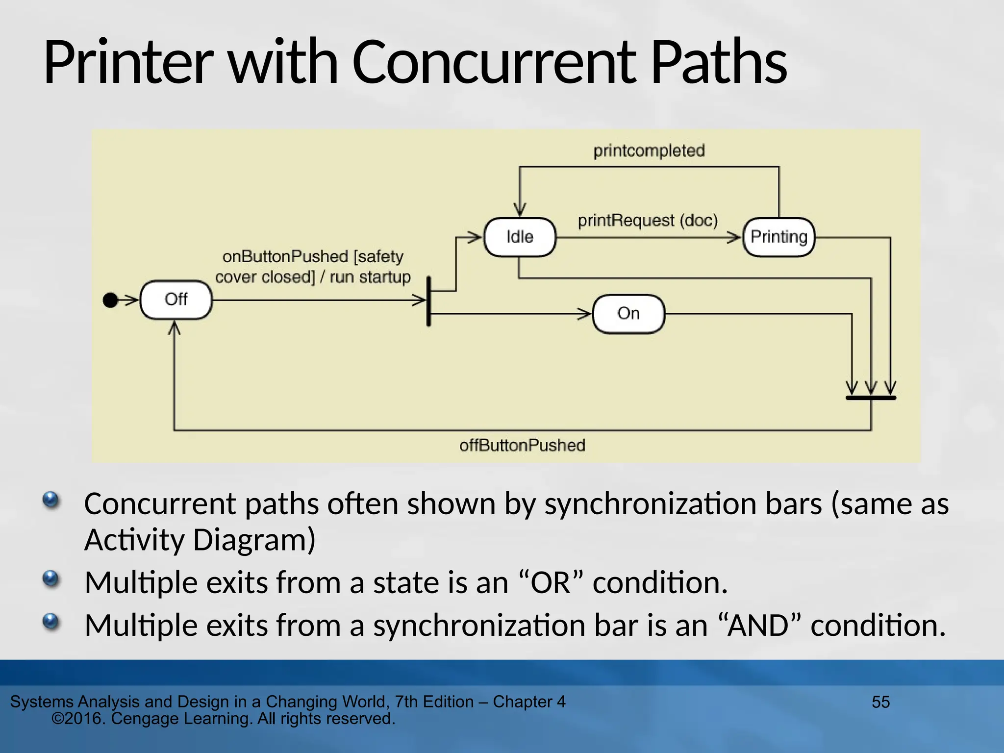
Design in a Changing World, 7th Edition – Chapter 4 ©2016. Cengage Learning. All rights reserved. Printer with Concurrent Paths Concurrent paths often shown by synchronization bars (same as Activity Diagram) Multiple exits from a state is an “OR” condition. Multiple exits from a synchronization bar is an “AND” condition.
56.
56 Systems Analysis and
Design in a Changing World, 7th Edition – Chapter 4 ©2016. Cengage Learning. All rights reserved. Creatinga StateMachineDiagram Steps 1. Review the class diagram and select classes that might require state machine diagrams 2. For each class, make a list of status conditions (states) you can identify 3. Begin building diagram fragments by identifying transitions that cause an object to leave the identified state 4. Sequence these states in the correct order and aggregate combinations into larger fragments 5. Review paths and look for independent, concurrent paths
57.
57 Systems Analysis and
Design in a Changing World, 7th Edition – Chapter 4 ©2016. Cengage Learning. All rights reserved. Creatinga StateMachineDiagram Steps(continued) 6. Look for additional transitions and test both directions 7. Expand each transition with appropriate message event, guard condition, and action expression 8. Review and test the state machine diagram for the class Make sure state are really state for the object in the class Follow the life cycle of an object coming into existence and being deleted Be sure the diagram covers all exception condition Look again for concurrent paths and composite states
58.
58 Systems Analysis and
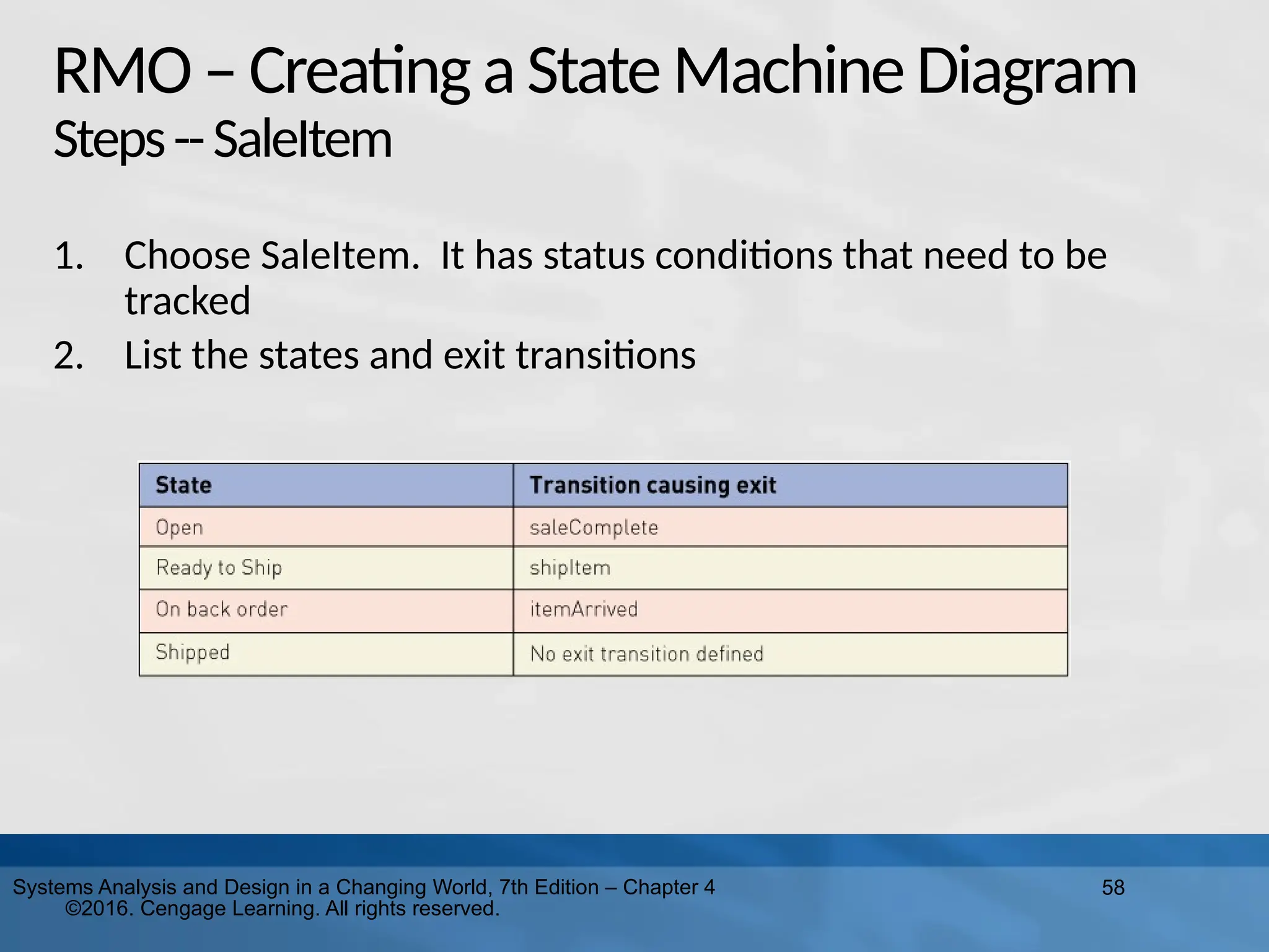
Design in a Changing World, 7th Edition – Chapter 4 ©2016. Cengage Learning. All rights reserved. RMO–Creating aStateMachineDiagram Steps--SaleItem 1. Choose SaleItem. It has status conditions that need to be tracked 2. List the states and exit transitions
59.
59 Systems Analysis and
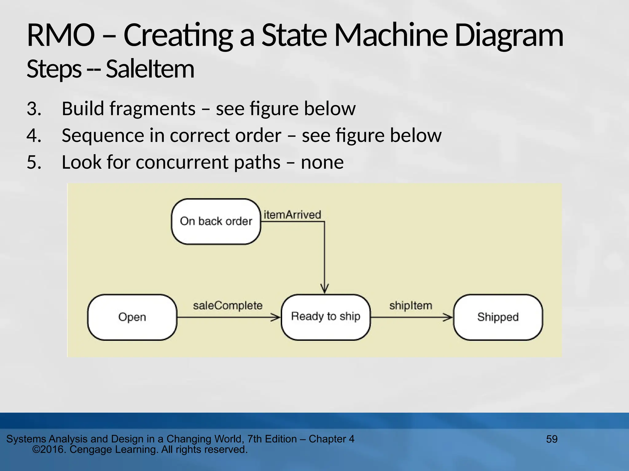
Design in a Changing World, 7th Edition – Chapter 4 ©2016. Cengage Learning. All rights reserved. RMO–Creating aStateMachineDiagram Steps--SaleItem 3. Build fragments – see figure below 4. Sequence in correct order – see figure below 5. Look for concurrent paths – none
60.
60 Systems Analysis and
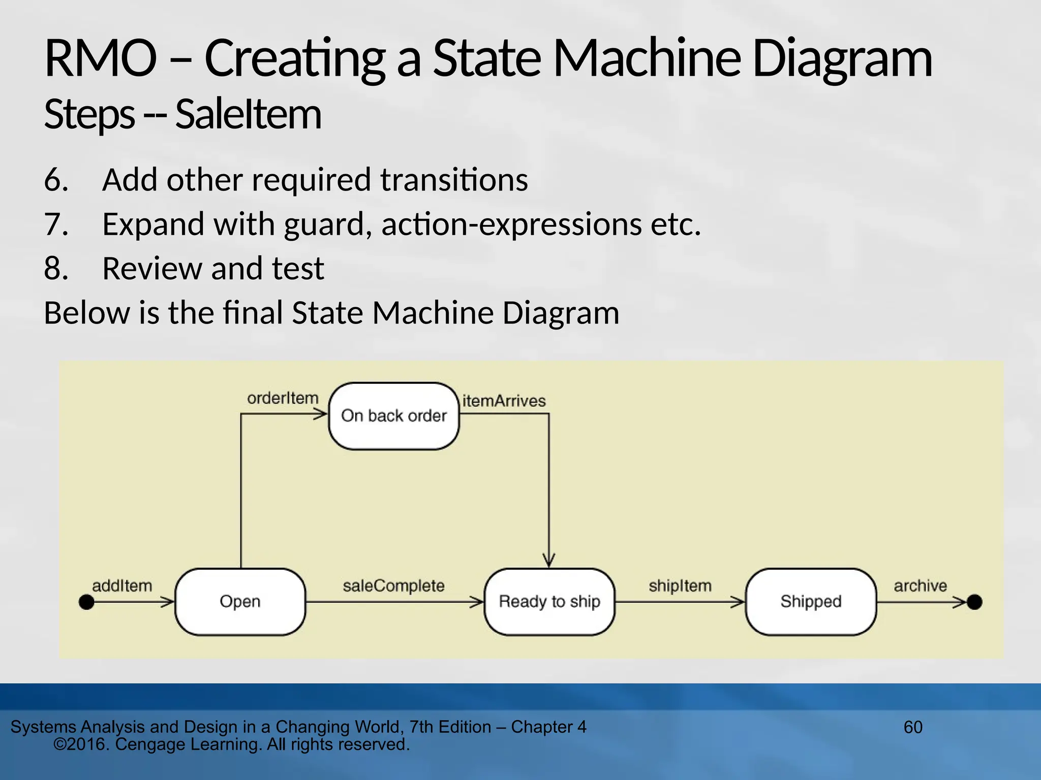
Design in a Changing World, 7th Edition – Chapter 4 ©2016. Cengage Learning. All rights reserved. RMO–Creating aStateMachineDiagram Steps--SaleItem 6. Add other required transitions 7. Expand with guard, action-expressions etc. 8. Review and test Below is the final State Machine Diagram
61.
61 Systems Analysis and
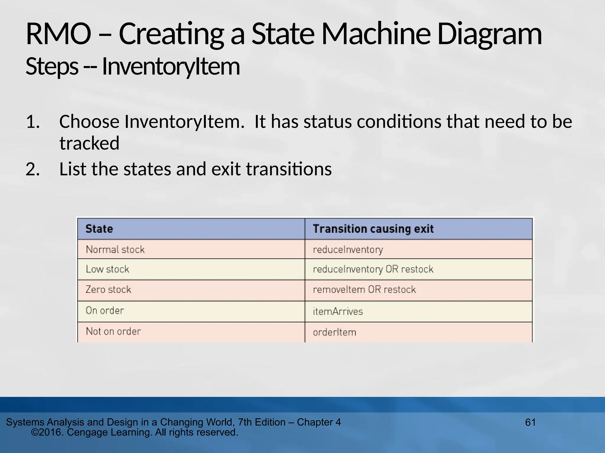
Design in a Changing World, 7th Edition – Chapter 4 ©2016. Cengage Learning. All rights reserved. RMO–Creating aStateMachineDiagram Steps--InventoryItem 1. Choose InventoryItem. It has status conditions that need to be tracked 2. List the states and exit transitions
62.
62 Systems Analysis and
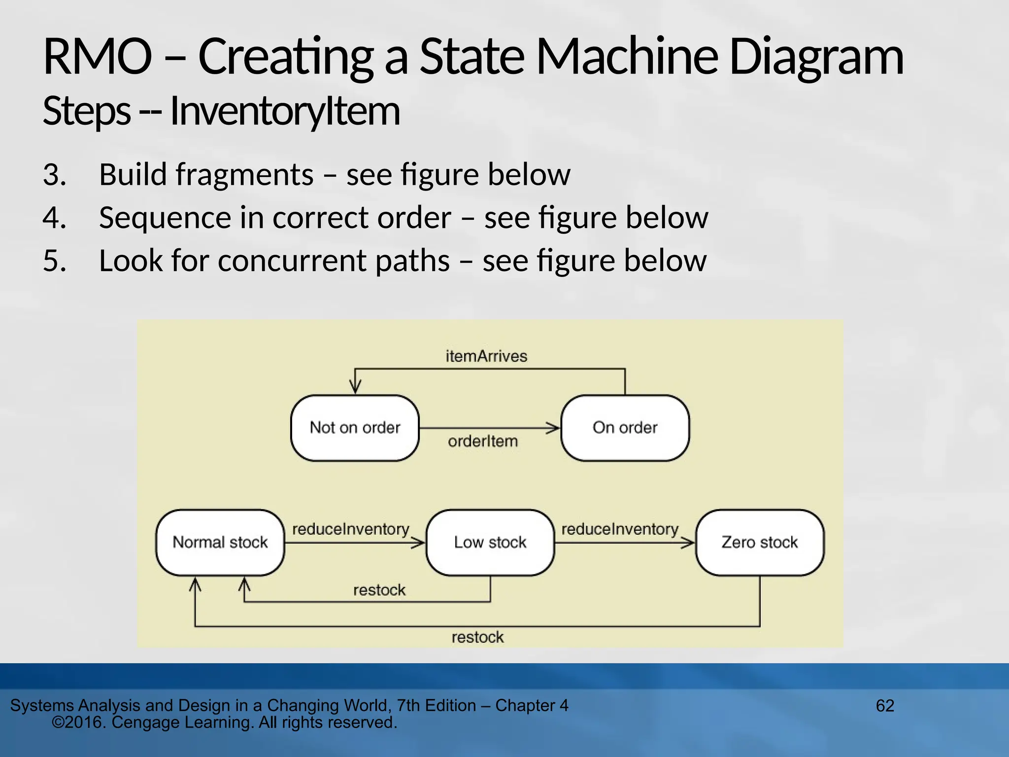
Design in a Changing World, 7th Edition – Chapter 4 ©2016. Cengage Learning. All rights reserved. RMO–Creating aStateMachineDiagram Steps--InventoryItem 3. Build fragments – see figure below 4. Sequence in correct order – see figure below 5. Look for concurrent paths – see figure below
63.
63 Systems Analysis and
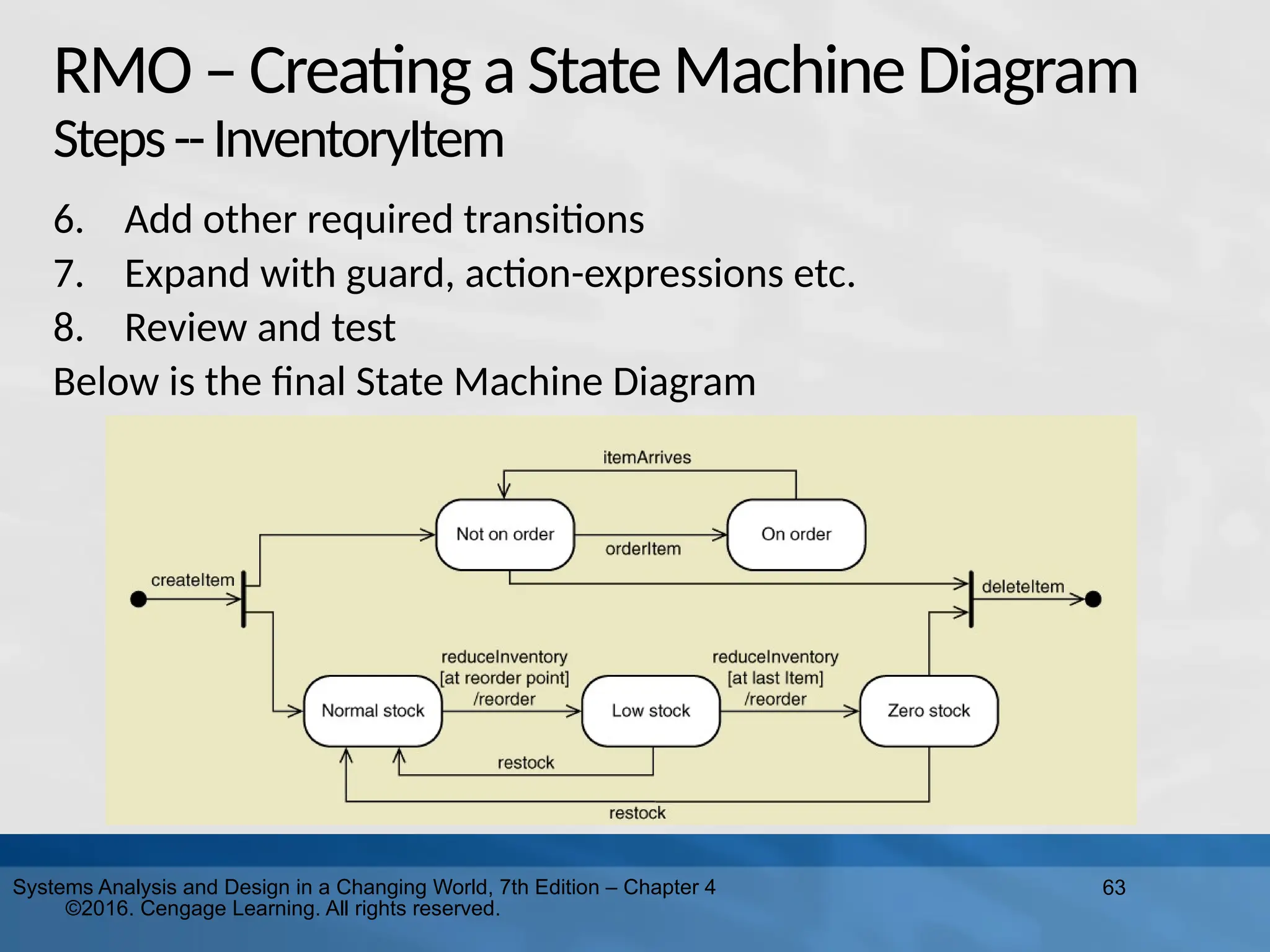
Design in a Changing World, 7th Edition – Chapter 4 ©2016. Cengage Learning. All rights reserved. RMO–Creating aStateMachineDiagram Steps--InventoryItem 6. Add other required transitions 7. Expand with guard, action-expressions etc. 8. Review and test Below is the final State Machine Diagram
64.
Summary This chapter focuses
on modeling functional requirements as a part of systems analysis “Things” in the problem domain are identified and modeled, called domain classes or data entities Two techniques for identifying domain classes/data entities are the brainstorming technique and the noun technique Domain classes have attributes and associations Associations are naturally occurring relationships among classes, and associations have minimum and maximum multiplicity 64 Systems Analysis and Design in a Changing World, 7th Edition – Chapter 4 ©2016. Cengage Learning. All rights reserved.
65.
Summary Entity-relationship diagrams (ERDs)
show the information about data entities ERDs are often preferred by database analysts and are widely used ERDs are not UML diagrams, and an association is called a relationship, multiplicity is called cardinality, and generalization/specialization (inheritance) and whole part relationships are usually not shown Systems Analysis and Design in a Changing World, 7th Edition – Chapter 4 ©2016. Cengage Learning. All rights reserved. 65
66.
Summary The UML class
diagram notation is used to create a domain model class diagram for a system. The domain model classes do not have methods because they are not yet software classes. There are actually three UML class diagram relationships: association relationships, generalization/specialization (inheritance) relationships, and whole part relationships Other class diagram concepts are abstract versus concrete classes, compound attributes, composition and aggregation, association classes, super classes and subclasses Systems Analysis and Design in a Changing World, 7th Edition – Chapter 4 ©2016. Cengage Learning. All rights reserved. 66
67.
67 Systems Analysis and
Design in a Changing World, 7th Edition – Chapter 4 ©2016. Cengage Learning. All rights reserved. Summary Some objects have a life cycle with status conditions that change and should be tracked A State Machine Diagram tracks the behavior of these objects with states and transitions To develop a State Machine Diagram Choose a single object class. Identify the states and exit transitions Identify concurrent paths Identify additional paths Build the State Machine Diagram
68.
68 Systems Analysis and
Design in a Changing World, 7th Edition – Chapter 4 ©2016. Cengage Learning. All rights reserved. Summary Draw an entity-relationship diagram, including minimum and maximum cardinality, for the following: The system stores information about two things: cars and owners. A car has attributes for make, model, and year. The owner has attributes for name and address. Assume that a car must be owned by one owner and an owner can own many cars, but an owner might not own any cars (perhaps she just sold them all, but you still want a record of her in the system).
69.
69 Systems Analysis and
Design in a Changing World, 7th Edition – Chapter 4 ©2016. Cengage Learning. All rights reserved. Summary Draw a class diagram for the cars and owners described in exercise 1, but include subclasses for sports car, sedan, and minivan, with appropriate attributes.
70.
70 Systems Analysis and
Design in a Changing World, 7th Edition – Chapter 4 ©2016. Cengage Learning. All rights reserved. Summary Draw a class diagram for the cars and owners described in exercise 1, but include subclasses for sports car, sedan, and minivan, with appropriate attributes.
Download
![53
Systems Analysis and Design in a Changing World, 7th Edition – Chapter 4
©2016. Cengage Learning. All rights reserved.
State Machine for a Printer
Syntax of transition statement
transition-name (parameters, …) [guard-condition] / action-expression](https://image.slidesharecdn.com/lu6umls-250917175435-f7bf9e1d/75/Learning-Unit-6-Unified-Modeling-Ls-pptx-53-2048.jpg)