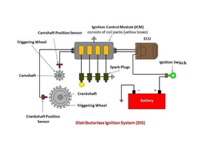
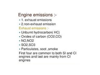
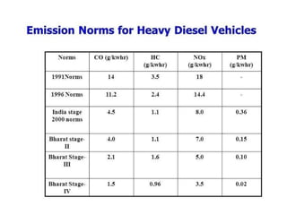
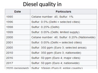
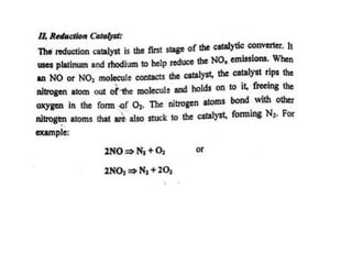
ME 8091 AUTOMOBILE ENGINEERING
UNIT-2
AUXILLARY SYSTEMS
ENGINE AUXILIARYSYSTEMS
 Injection system
 Ignition system
 Turbocharger
 Catalytic convertor
Electronically controlled gasoline injection system for SI engines,
Electronically controlled diesel injection system (Unit injector
system Rotary distributor type and common rail direct injection
system).
Electronic ignition system (Transistorized coil ignition system,
capacitive
discharge ignition system).
Turbo chargers (WGT, VGT).
Engine emission control by three way catalytic converter system,
Emission norms (Euro and BS).
TRANSMISSION SYSTEMS
 Clutch-types and construction.
 Gear boxes- manual and automatic, gear shift mechanisms, Over
drive, transfer box, fluid flywheel, torque converter, propeller
shaft, slip joints, universal joints.
 Differential and rear axle.
 Hotchkiss Drive and Torque Tube Drive
STEERING, BRAKES AND SUSPENSION SYSTEMS
 Steering geometry and types of steering gear box-Power
Steering.
 Types of Front Axle, Types of Suspension Systems,
 Pneumatic and Hydraulic Braking Systems, Antilock Braking
System (ABS).
 Electronic brake force distribution (EBD) and Traction
Control.
ALTERNATIVE ENERGY SOURCES
Use of Natural Gas, Liquefied Petroleum Gas.
Bio-diesel, Bio-ethanol, Gasohol
Hydrogen in Automobiles- Engine modifications required –
Performance, Combustion and Emission Characteristics of SI and
CI engines with these alternate fuels.
Electric and Hybrid Vehicles.
Fuel Cell Note: Practical Training in dismantling and assembling
of Engine parts and Transmission Systems should be given to the
students.
16 MARKS
1. Discuss in detail about Electronic fuel injection system for S.I
engine.
2. Explain i). MPFI and ii). CRDI fuel injection system
3. Discuss in detail about Electronic fuel injection system for C.I
engine.
4. With a clear sketch explain Electronic Ignition system.
5. Explain in detail about Transistorized coil ignition system.
6. Explain in detail about Capacitive discharge ignition system.
7. What is 3 way catalytic converter? Explain its working principle.
8. Explain the turbo charging system with neat sketch.
9. Illustrate with a sketch the working of a Unit injector system..
10. What is supercharger. Explain anyone method of supercharger.
DIESEL INJECTION
SYSTEM
What is a CDI System?
A Capacitive Discharge Ignition is an electronic ignition device
that stores an electrical charge and then discharges it through
an ignition coil in order to produce a powerful spark from the
spark plugs in a petrol engine. Here the ignition is provided by
the capacitor charge. The capacitor simply charges and
discharges within a fraction of time making it possible to create
sparks CDIs are commonly found on motorbikes and scooters.
Advantages of CDI
•The major advantage of CDI is that the capacitor can be fully charged
in a very short time (typically 1ms). So the CDI is suited to an application
where the insufficient dwell time is available.
•The capacitor discharge ignition system has a short transient response,
a fast voltage rise (between 3 to 10 kV/ µs) compared to inductive
systems (300 to 500 V/ µs) and shorter spark duration (about 50-80 µs).
•The fast voltage rising makes CDI systems unaffected to shunt
resistance.
Disadvantages of CDI
•The capacitor discharge ignition system generates huge
electromagnetic noise and this is the main reason why CDIs are rarely
used by automobile manufacturers.
•The short spark duration is not good for lighting relatively lean
mixtures as used at low power levels. To solve this problem many CDI
ignitions release multiple sparks at low engine speeds.
Diesel quality in
india
TURBOCHARGER
INTRODUCTION
• An engine may not produce the same power output when it
is
operated at different locations and altitudes.
• This is due to variation in ambient conditions.
• Supercharging and turbo charging are used to overcome
this problem.
Increasing the engine displacement: This increases the size and
weight of the engine, and introduces additional cooling
problems.
Running the engine at higher speeds: This results in increased
mechanical friction losses and imposes greater inertia stresses
on engine parts.
Increasing the density of the charge: This allows a greater
mass of the charge to be inducted into the same volume.
SUPERCHARGER
The most efficient method of increasing the power of an engine is
by supercharging, i.e. increasing the flow of air into the engine to
enable more fuel to be burnt.
• A Supercharger is run by the mechanical drive, poweredby
engine power .
• The rotation of the compressor pushes more air into the
cylinder above the atmosphere pressure, thus capable of
digesting more fuel and deliver more power.
• A turbocharger uses the unused energy in the exhaust gases to
drive a turbine directly connected by a co-axial shaft to a rotary
compressor in the air intake system.
FIGURE The more air and fuel that can be
packed in a cylinder, the greater the densityof
the air–fuel charge.
SUPERCHARGER
SUPERCHARGING
PRINCIPLES
FIGURE 7-4 Atmospheric pressure decreases with increases in altitude.
PSi- pound per square inch
NEED OF TURBOCHARGER AND SUPER CHARGER
• For ground installations, it is used to produce a gain in the
power out put of the engine.
• For aircraft installations, in addition to produce a gain in
the power out put at sea-level, it also enables the engine to
maintain a higher power out put as altitude is increased.
WORKING PRINCIPLE OF ATURBOCHARGER:
• A turbocharger is a small radial fan pump driven by the energyof
the exhaust gases of an engine.
•
A turbocharger consists of a turbine and a compressor
on a shared shaft.
• The turbine converts exhaust gas flow into a rotational
force, which is in turn used to drive the compressor.
• The compressor draws in ambient air and pumps it in to the
intake manifold to increase the pressure, resulting in a
greater mass of air entering the cylinders on each intake
stroke.
TYPES OF SUPER CHARGER:
Based on the use of
compressor
• Centrifugal type
• Roots type
• Vane type
Components of
turbocharger
•Air compressor
•Turbine
•Intercooler
Advantages of supercharger and turbocharger
• The more increase the pressure of the intake air above
the local atmospheric pressure (boost), the more power
the engine produces.
• This is particularly useful at high altitudes: thinner air has
less oxygen, reducing power by around 3% per 1,000
feet above sea level, but a supercharger can
compensate for that loss, pressurizing the
intake charge to something close to sea level
pressure.
DISADVANTAGES OF TURBOCHARGER
AND SUPERCHARGER
• Cost and complexity
• Detonation
• Parasitic losses- the take energy from the engine in order
to enhance the engine's ability to create more energy.
• Space
• Turbo lag- But it has its draw back. Unless when the engine
is working at high loads the energy in the exhaust gas is not
sufficient to quickly rev up the impeller and create surge in
power. This phenomenon is called turbo lag.
CATALYTIC CONVERTER
Three way catalytic convertor
2 MARKS
25.What is the purpose of the grid?
The more "plates" in the grid, the more surface area exposed to the electrolyte,
hence the more power produced.
26.How will you distinguish a positive plate from a negative plate in a lead
acid battery?
The positive plates are coated with PbO2 and chocolate brown in color
The negative plates are coated with spongy lead and grey in color.
27.What is the function a cut out in a charging system?
The cut out permits the current flow from dynamo/alternator to battery for charging
while it does not permit the reverse flow of current.
28. What is the function of regulators in a charging system?
Current regulator – regulates the alternator/dynamo current for charging the battery
(constant current charging mode)
Voltage regulator – regulates the alternator/dynamo voltage for charging the battery
(constant voltage charging mode)

unit 2-Automobile engineering for mechanical engineers

  • 1.
    ME 8091 AUTOMOBILEENGINEERING UNIT-2 AUXILLARY SYSTEMS
  • 2.
    ENGINE AUXILIARYSYSTEMS  Injectionsystem  Ignition system  Turbocharger  Catalytic convertor Electronically controlled gasoline injection system for SI engines, Electronically controlled diesel injection system (Unit injector system Rotary distributor type and common rail direct injection system). Electronic ignition system (Transistorized coil ignition system, capacitive discharge ignition system). Turbo chargers (WGT, VGT). Engine emission control by three way catalytic converter system, Emission norms (Euro and BS).
  • 3.
    TRANSMISSION SYSTEMS  Clutch-typesand construction.  Gear boxes- manual and automatic, gear shift mechanisms, Over drive, transfer box, fluid flywheel, torque converter, propeller shaft, slip joints, universal joints.  Differential and rear axle.  Hotchkiss Drive and Torque Tube Drive
  • 4.
    STEERING, BRAKES ANDSUSPENSION SYSTEMS  Steering geometry and types of steering gear box-Power Steering.  Types of Front Axle, Types of Suspension Systems,  Pneumatic and Hydraulic Braking Systems, Antilock Braking System (ABS).  Electronic brake force distribution (EBD) and Traction Control.
  • 5.
    ALTERNATIVE ENERGY SOURCES Useof Natural Gas, Liquefied Petroleum Gas. Bio-diesel, Bio-ethanol, Gasohol Hydrogen in Automobiles- Engine modifications required – Performance, Combustion and Emission Characteristics of SI and CI engines with these alternate fuels. Electric and Hybrid Vehicles. Fuel Cell Note: Practical Training in dismantling and assembling of Engine parts and Transmission Systems should be given to the students.
  • 6.
    16 MARKS 1. Discussin detail about Electronic fuel injection system for S.I engine. 2. Explain i). MPFI and ii). CRDI fuel injection system 3. Discuss in detail about Electronic fuel injection system for C.I engine. 4. With a clear sketch explain Electronic Ignition system. 5. Explain in detail about Transistorized coil ignition system. 6. Explain in detail about Capacitive discharge ignition system. 7. What is 3 way catalytic converter? Explain its working principle. 8. Explain the turbo charging system with neat sketch. 9. Illustrate with a sketch the working of a Unit injector system.. 10. What is supercharger. Explain anyone method of supercharger.
  • 32.
  • 59.
    What is aCDI System? A Capacitive Discharge Ignition is an electronic ignition device that stores an electrical charge and then discharges it through an ignition coil in order to produce a powerful spark from the spark plugs in a petrol engine. Here the ignition is provided by the capacitor charge. The capacitor simply charges and discharges within a fraction of time making it possible to create sparks CDIs are commonly found on motorbikes and scooters.
  • 60.
    Advantages of CDI •Themajor advantage of CDI is that the capacitor can be fully charged in a very short time (typically 1ms). So the CDI is suited to an application where the insufficient dwell time is available. •The capacitor discharge ignition system has a short transient response, a fast voltage rise (between 3 to 10 kV/ µs) compared to inductive systems (300 to 500 V/ µs) and shorter spark duration (about 50-80 µs). •The fast voltage rising makes CDI systems unaffected to shunt resistance. Disadvantages of CDI •The capacitor discharge ignition system generates huge electromagnetic noise and this is the main reason why CDIs are rarely used by automobile manufacturers. •The short spark duration is not good for lighting relatively lean mixtures as used at low power levels. To solve this problem many CDI ignitions release multiple sparks at low engine speeds.
  • 68.
  • 73.
  • 74.
    INTRODUCTION • An enginemay not produce the same power output when it is operated at different locations and altitudes. • This is due to variation in ambient conditions. • Supercharging and turbo charging are used to overcome this problem.
  • 75.
    Increasing the enginedisplacement: This increases the size and weight of the engine, and introduces additional cooling problems. Running the engine at higher speeds: This results in increased mechanical friction losses and imposes greater inertia stresses on engine parts. Increasing the density of the charge: This allows a greater mass of the charge to be inducted into the same volume.
  • 76.
    SUPERCHARGER The most efficientmethod of increasing the power of an engine is by supercharging, i.e. increasing the flow of air into the engine to enable more fuel to be burnt. • A Supercharger is run by the mechanical drive, poweredby engine power . • The rotation of the compressor pushes more air into the cylinder above the atmosphere pressure, thus capable of digesting more fuel and deliver more power. • A turbocharger uses the unused energy in the exhaust gases to drive a turbine directly connected by a co-axial shaft to a rotary compressor in the air intake system.
  • 77.
    FIGURE The moreair and fuel that can be packed in a cylinder, the greater the densityof the air–fuel charge. SUPERCHARGER
  • 78.
    SUPERCHARGING PRINCIPLES FIGURE 7-4 Atmosphericpressure decreases with increases in altitude. PSi- pound per square inch
  • 79.
    NEED OF TURBOCHARGERAND SUPER CHARGER • For ground installations, it is used to produce a gain in the power out put of the engine. • For aircraft installations, in addition to produce a gain in the power out put at sea-level, it also enables the engine to maintain a higher power out put as altitude is increased.
  • 80.
    WORKING PRINCIPLE OFATURBOCHARGER: • A turbocharger is a small radial fan pump driven by the energyof the exhaust gases of an engine. • A turbocharger consists of a turbine and a compressor on a shared shaft. • The turbine converts exhaust gas flow into a rotational force, which is in turn used to drive the compressor. • The compressor draws in ambient air and pumps it in to the intake manifold to increase the pressure, resulting in a greater mass of air entering the cylinders on each intake stroke.
  • 81.
    TYPES OF SUPERCHARGER: Based on the use of compressor • Centrifugal type • Roots type • Vane type Components of turbocharger •Air compressor •Turbine •Intercooler
  • 82.
    Advantages of superchargerand turbocharger • The more increase the pressure of the intake air above the local atmospheric pressure (boost), the more power the engine produces. • This is particularly useful at high altitudes: thinner air has less oxygen, reducing power by around 3% per 1,000 feet above sea level, but a supercharger can compensate for that loss, pressurizing the intake charge to something close to sea level pressure.
  • 84.
    DISADVANTAGES OF TURBOCHARGER ANDSUPERCHARGER • Cost and complexity • Detonation • Parasitic losses- the take energy from the engine in order to enhance the engine's ability to create more energy. • Space • Turbo lag- But it has its draw back. Unless when the engine is working at high loads the energy in the exhaust gas is not sufficient to quickly rev up the impeller and create surge in power. This phenomenon is called turbo lag.
  • 85.
  • 88.
  • 89.
  • 97.
    25.What is thepurpose of the grid? The more "plates" in the grid, the more surface area exposed to the electrolyte, hence the more power produced. 26.How will you distinguish a positive plate from a negative plate in a lead acid battery? The positive plates are coated with PbO2 and chocolate brown in color The negative plates are coated with spongy lead and grey in color. 27.What is the function a cut out in a charging system? The cut out permits the current flow from dynamo/alternator to battery for charging while it does not permit the reverse flow of current. 28. What is the function of regulators in a charging system? Current regulator – regulates the alternator/dynamo current for charging the battery (constant current charging mode) Voltage regulator – regulates the alternator/dynamo voltage for charging the battery (constant voltage charging mode)