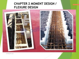
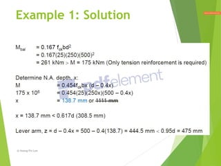
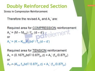
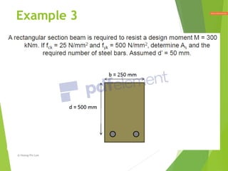
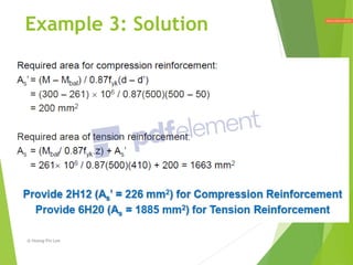
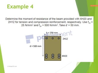
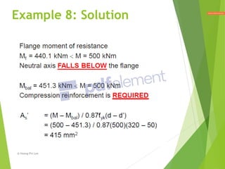
CHAPTER 2 MOMENT DESIGN /
FLEXURE DESIGN
@ Hoong-Pin Lee
@ Hoong-Pin Lee
DESIGN METHOD / PROCEDURES
Based on Section 6.1 MS EN 1992-1-1 – ULS analysis
and design of section subjected to bending
@ Hoong-Pin Lee
In this chapter, you’ll learn
about:
 Rectangular section: Singly and doubly
reinforced
 Flanged section: Singly and doubly
reinforced
@ Hoong-Pin Lee
Two different types of problems
in the study of RC flexural
elements:
 (1) Design:
 Given a cross-section, concrete strength, steel
reinforcement strength, and applied ultimate bending
moment, determine the area and number of
reinforcement required.
 (2) Design Check:
 Given a cross-section, concrete strength, number, strength
and size of steel reinforcement provided, determine the
moment of resistance.
@ Hoong-Pin Lee
Which one is T, L, & Rectangular?
@ Hoong-Pin Lee
Stress Block Diagram
S = 0.8x
𝑓𝑐𝑑 = 0.567𝑓𝑐𝑘
𝜇 = 1.0
Lecture 1, slide 35
𝑓𝑦𝑑 = 0.87𝑓𝑦𝑘
Lecture 1, slide 38
@ Hoong-Pin Lee
Singly Reinforced Section
Stress Area
@ Hoong-Pin Lee
Singly Reinforced Section
@ Hoong-Pin Lee
Singly Reinforced Section
(to avoid sudden failure)
@ Hoong-Pin Lee
Singly Reinforced Section
@ Hoong-Pin Lee
Example 1
@ Hoong-Pin Lee
Example 1: Solution
@ Hoong-Pin Lee
Example 1: Solution
@ Hoong-Pin Lee
Example 2
@ Hoong-Pin Lee
Example 2: Solution
@ Hoong-Pin Lee
Example 2: Solution
@ Hoong-Pin Lee
Doubly Reinforced Section
@ Hoong-Pin Lee
Doubly Reinforced Section
@ Hoong-Pin Lee
Doubly Reinforced Section
@ Hoong-Pin Lee
Doubly Reinforced Section
@ Hoong-Pin Lee
Doubly Reinforced Section
Stress in Compression Reinforcement
@ Hoong-Pin Lee
Doubly Reinforced Section
Stress in Compression Reinforcement
(a reduced stress should be used)
Reduced stress formula
@ Hoong-Pin Lee
Doubly Reinforced Section
Stress in Compression Reinforcement
@ Hoong-Pin Lee
Example 3
@ Hoong-Pin Lee
Example 3: Solution
@ Hoong-Pin Lee
Example 3: Solution
@ Hoong-Pin Lee
Example 3: Solution
@ Hoong-Pin Lee
Example 4
@ Hoong-Pin Lee
Example 4: Solution
@ Hoong-Pin Lee
Example 4: Solution
@ Hoong-Pin Lee
 The plastic behavior of reinforced concrete at the ULS affects
the distribution of moments in a structure.
 To allow for this, the moment derived from an elastic analysis
may be redistributed based on the assumption that plastic
hinges have formed at the sections with the largest moments.
 Formation of plastic hinges required relatively large rotations
with yielding of the tension reinforcement.
 To ensure large strain in the tension steel, the code of practice
restricts the depth of the neutral axis to correspond with the
magnitude of the moment redistribution carried out.
Moment REDistribution
@ Hoong-Pin Lee
Plastic Hinges
@ Hoong-Pin Lee
Moment Distribution
@ Hoong-Pin Lee
Moment Distribution
@ Hoong-Pin Lee
Moment Distribution
Prove this equation!
@ Hoong-Pin Lee
Moment Distribution
@ Hoong-Pin Lee
Derivation of z Equation
(S = 0.8x)
@ Hoong-Pin Lee
Simplified EC2 Method
@ Hoong-Pin Lee
Simplified EC2 Method
@ Hoong-Pin Lee
Simplified EC2 Method
@ Hoong-Pin Lee
Example 5
@ Hoong-Pin Lee
Example 5: Solution
@ Hoong-Pin Lee
Example 5: Solution
@ Hoong-Pin Lee
Example 5: Solution
@ Hoong-Pin Lee
Flanged Beam/Section
A portion of slab act integrally with the beam
in longitudinal direction.
WEB
WEB
@ Hoong-Pin Lee
 When the flange is relatively wide, the flexural
compressive stress is not uniform over its width.
 The stress varies from a maximum in the web region to
progressively lower values at points farther away from
the web.
 In order to operate within the framework of the theory
of flexural, which assumes a uniform stress distribution
across the width of the section,
 IT IS NECESSARY TO DEFINE AN EFFECTIVE FLANGE
WIDTH
Flanged Beam/Section
@ Hoong-Pin Lee
Flanged Beam
Cl 5.3.2.1 (EC2)
@ Hoong-Pin Lee
How to determine 𝒃𝒆𝒇𝒇?
@ Hoong-Pin Lee
How to determine 𝒃𝒆𝒇𝒇?
@ Hoong-Pin Lee
Design Consideration
@ Hoong-Pin Lee
Neutral Axis Lies in the Flange
Note: All the concrete on the tension side is assumed
ineffective in flexural computations, and the flanged
beam may just as well be treated as a rectangular section
having a width 𝑏𝑒𝑓𝑓.
@ Hoong-Pin Lee
Neutral Axis Lies in the Flange
(Maximum Case)
@ Hoong-Pin Lee
Example 6
@ Hoong-Pin Lee
Example 6: Solution
@ Hoong-Pin Lee
Example 6: Solution
@ Hoong-Pin Lee
Design Consideration
@ Hoong-Pin Lee
Neutral Axis Lies below the
Flange
@ Hoong-Pin Lee
Neutral Axis Lies below the
Flange
(Take moment @ steel reinforcement)
@ Hoong-Pin Lee
Neutral Axis Lies below the
Flange
@ Hoong-Pin Lee
Neutral Axis Lies below the
Flange
@ Hoong-Pin Lee
Example 7
@ Hoong-Pin Lee
Example 7: Solution
@ Hoong-Pin Lee
Example 7: Solution
@ Hoong-Pin Lee
Example 7: Solution
@ Hoong-Pin Lee
Design Consideration
@ Hoong-Pin Lee
Neutral Axis Lies below the
Flange (M>𝑴𝒃𝒂𝒍 )
@ Hoong-Pin Lee
Neutral Axis Lies below the
Flange (M>𝑴𝒃𝒂𝒍 )
@ Hoong-Pin Lee
Neutral Axis Lies below the
Flange (M>𝑴𝒃𝒂𝒍 )
@ Hoong-Pin Lee
Example 8
@ Hoong-Pin Lee
Example 8: Solution
@ Hoong-Pin Lee
Example 8: Solution
@ Hoong-Pin Lee
Example 8: Solution
@ Hoong-Pin Lee
Design Summary for Flanged
Beam
@ Hoong-Pin Lee
Design Summary for Flanged
Beam
@ Hoong-Pin Lee
End of Chapter 2
@ Hoong-Pin Lee

L2 - Moment Design.pdf