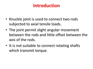
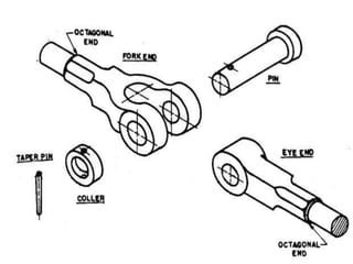
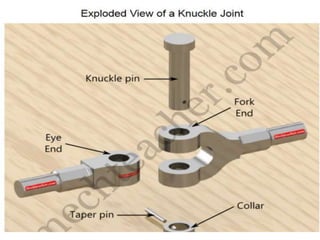
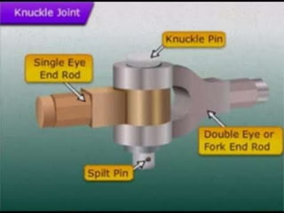
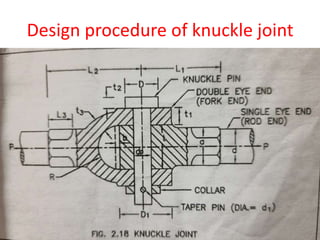
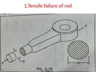
The document summarizes the design of a knuckle joint used to connect two rods subjected to axial tensile loads. It describes the main parts of a knuckle joint including the single eye end, double eye end, knuckle pin, and collar. It then provides the design procedure which involves checking for tensile, shear, crushing, and bending failures. As an example, it provides the design of a knuckle joint to connect two 16mm rods subjected to a tensile load of 12kN, calculating dimensions to ensure it is safe against various failure modes.


![• As shown in fig. The pin may fail in double
shear due to tensile load
• P=2× Л/4×dp
2×[τ]
• Where dp=pin diameter](https://image.slidesharecdn.com/knucklejoint-230425163502-9355b565/85/knuckle-joint-pptx-15-320.jpg)
![• Eye dimension are obtained by taking
proportions.
• D1=2dp; t=1.2 dp
• Checking the eye for tensile failure
• P=( D1 - dp )×t× σt
• If σt˂[ σt] the eye is safe for tensile failure](https://image.slidesharecdn.com/knucklejoint-230425163502-9355b565/85/knuckle-joint-pptx-17-320.jpg)
![• P= dp ×t × σc
• If σc˂[ σc] the eye / pin is safe for crushing
failure](https://image.slidesharecdn.com/knucklejoint-230425163502-9355b565/85/knuckle-joint-pptx-19-320.jpg)
![• P=2(D1- dp )t1× σt
• If σt˂[ σt] the double eye is safe for tensile
failure](https://image.slidesharecdn.com/knucklejoint-230425163502-9355b565/85/knuckle-joint-pptx-23-320.jpg)
![• P=2×[(D1- dp )/2] ×t×τ
• If τ˂[ τ] the double eye end / single eye end is
safe against shear failure.](https://image.slidesharecdn.com/knucklejoint-230425163502-9355b565/85/knuckle-joint-pptx-25-320.jpg)
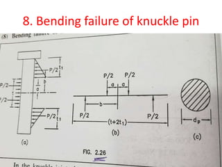
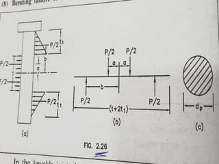
![• Bending moment , Mb =P/2×b - P/2×a
• =P/2 (b-a)
• b = t/2 +t1/3 ; a=t/4
• Mb =P/2[t/2 +t1/3 - t/4]
• =P/2 [t/4 +t1/3]
• Taking , t1 = t/2
•
• Mb= P/2 [t/4 +t/6]
• Mb =5/24 P×t
• σb = Mb/Z
• Z= Л/32 dp
3
• Here , If σb˂[ σb] the pin is safe for bending
•](https://image.slidesharecdn.com/knucklejoint-230425163502-9355b565/85/knuckle-joint-pptx-28-320.jpg)
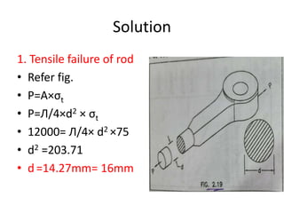
![Problem 1
• Design of knuckle joint to connect two m .s
rods of equal diameter subjected to axial
tensile load of 12kN
• [σt]=75N/mm2; [ σc ] =140 N/mm2; [τ]=55
N/mm2](https://image.slidesharecdn.com/knucklejoint-230425163502-9355b565/85/knuckle-joint-pptx-29-320.jpg)
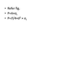
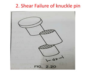
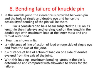
![2.Shear Failure of knuckle pin
• As shown in fig. The pin may fail in double shear due to
tensile load
• P=2× Л/4×dp
2×[τ]
• Where dp=pin diameter
• 12000=2× Л/4×dp
2×55
• dp =11.78
• note : here ,pin is also subjected to bending and hence
possibility of bending is more compared to shear.
Hence the diameter of pin is increased by 25% to 30%
to that obtained for shear failure.
• Generally for safety and simplicity in design , the pin
diameter is taken same as rod diameter.
• dp=d=16mm](https://image.slidesharecdn.com/knucklejoint-230425163502-9355b565/85/knuckle-joint-pptx-31-320.jpg)
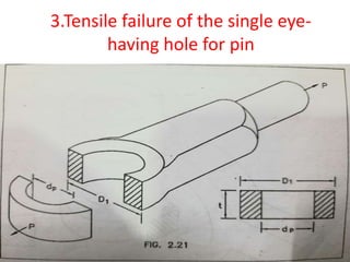
![3.Tensile failure of the single eye-
having hole for pin
• Eye dimension are obtained by taking proportions.
• D1=2dp; t=1.2 dp
• D1 =2×16=32mm
• t =1.2 ×16 =19.2=20mm
• Checking the eye for tensile failure
• P=( D1 - dp )×t× σt
• 12000=( 32 – 16)×20× σt
• σt =37.5 N/mm2
• allowable stress [σt]=75N/mm2
• as σt˂[ σt]
• The eye is safe for tensile failure
•](https://image.slidesharecdn.com/knucklejoint-230425163502-9355b565/85/knuckle-joint-pptx-32-320.jpg)
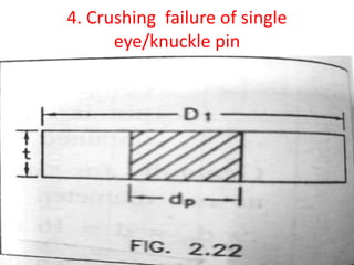
![4.Crushing failure of single
eye/knuckle pin
• P= dp ×t×σc
• 12000= 16 ×20×σc
• σc =37.5 N/mm2
• here, σc˂[ σc] ,
hence the eye / pin is safe for crushing failure
•](https://image.slidesharecdn.com/knucklejoint-230425163502-9355b565/85/knuckle-joint-pptx-33-320.jpg)
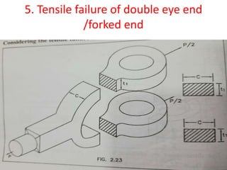
![5.Tensile failure of double eye end
/forked end
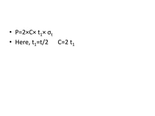
• P=2×C× t1× σt
• Here, t1=t/2 =20/2=10mm ;
C=2t1=2×10=20mm
• 12000=2×20× 10× σt
• σt =30 N/mm2
• here, σt˂[ σt] the double eye is safe for tensile
failure](https://image.slidesharecdn.com/knucklejoint-230425163502-9355b565/85/knuckle-joint-pptx-34-320.jpg)
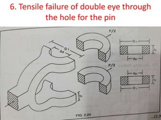
![6.Tensile failure of double eye through
the hole for the pin
• P=2(D1- dp )t1× σt
• 12000=2(32- 16 )10× σt
• σt =37.5 N/mm2
• here,σt˂[ σt],
hence double eye is safe for tensile failure](https://image.slidesharecdn.com/knucklejoint-230425163502-9355b565/85/knuckle-joint-pptx-35-320.jpg)
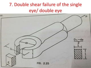
![7.Double shear failure of the single
eye/ double eye
• P=2×[(D1- dp )/2] ×t×τ
• 12000=2×[(32- 16 )/2] ×20×τ
• τ =37.5 N/mm2
• here , τ˂[ τ] ,
• hence the double eye end / single eye end is safe
against shear failure.](https://image.slidesharecdn.com/knucklejoint-230425163502-9355b565/85/knuckle-joint-pptx-36-320.jpg)
![• Bending moment,Mb =P/2×b - P/2×a
• =P/2 (b-a)
• b = t/2 +t1/3 ; a=t/4
• Mb =P/2[t/2 +t1/3 - t/4]
• =P/2 [t/4 +t1/3]
• Taking , t1 = t/2
•
• Mb= P/2 [t/4 +t/6]
• Mb =5/24 P×t
• σb = Mb/Z
• taking [σb ] =1.4 [σt ]
• [σb ]= 1.4×75
• [σb ] =105N/mm2
•
• Z= Л/32 dp
3 = Л/32 ×(16)3
• Z =402.12 mm3](https://image.slidesharecdn.com/knucklejoint-230425163502-9355b565/85/knuckle-joint-pptx-39-320.jpg)
![• Mb =5/24×12000×20
• Mb =50000N.mm
• σb = Mb/Z
• σb =50000/401.92
• σb =124.40 N/ mm2
• Here , σb˃[ σb] the pin is not safe in bending
• Let pin diameter, dp =20mm
• Z= Л/32 ×(20)3
• Z=785.39 mm3
• σb = Mb/Z
• σb = 50000/785.39
• σb =63.66 N/ mm2
• Here , σb˂[ σb] the pin is safe in bending](https://image.slidesharecdn.com/knucklejoint-230425163502-9355b565/85/knuckle-joint-pptx-40-320.jpg)


