Downloaded 563 times


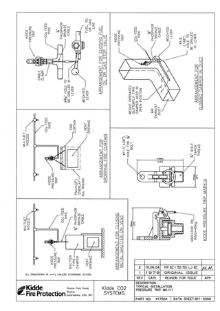
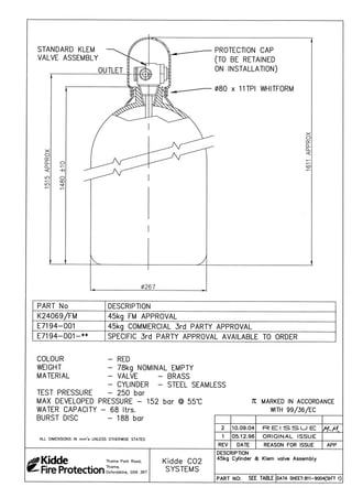
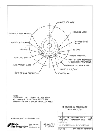
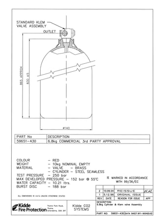
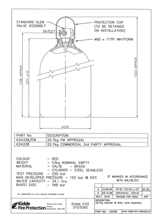
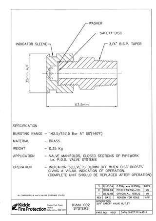
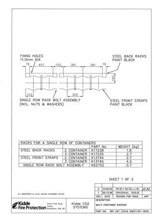
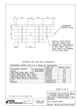
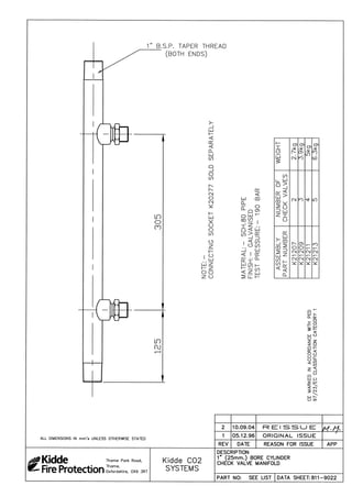
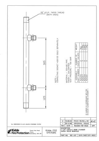
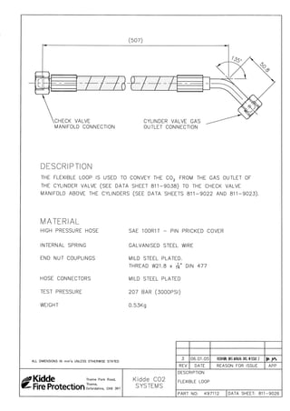
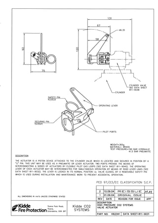
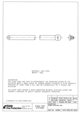
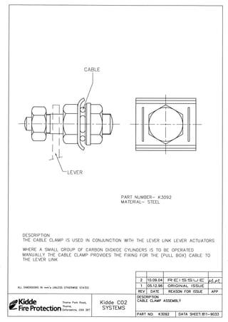
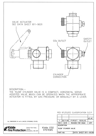
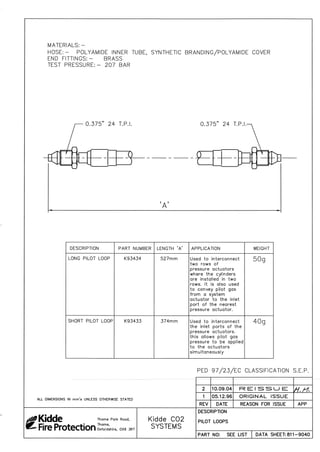
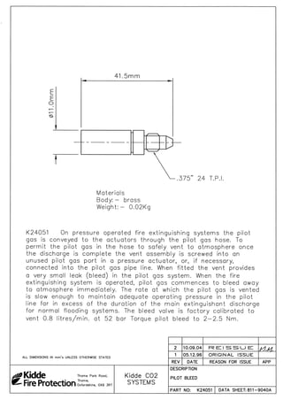
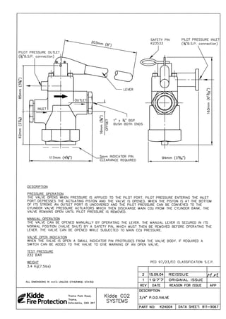
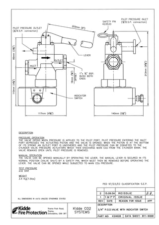
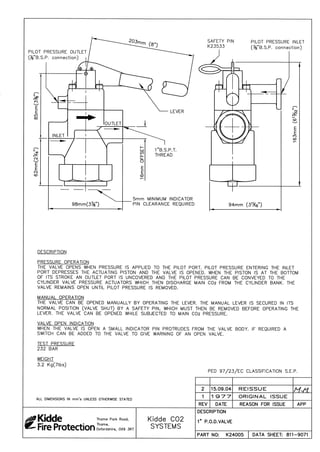
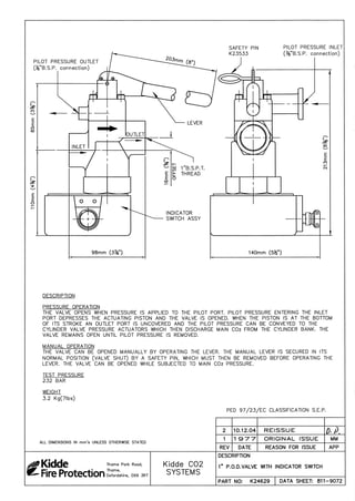
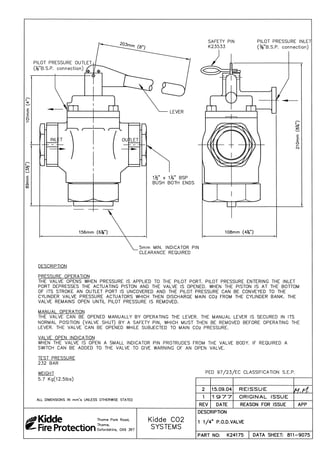
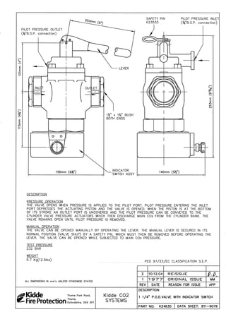
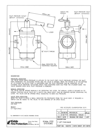
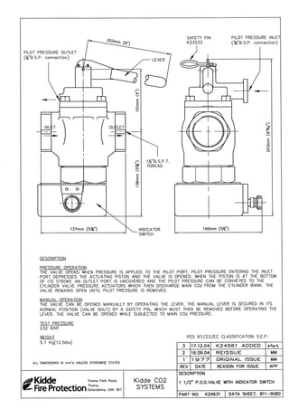
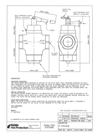
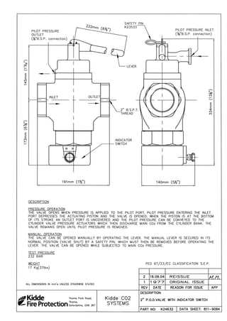
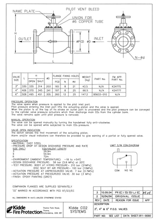
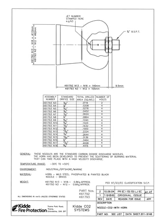
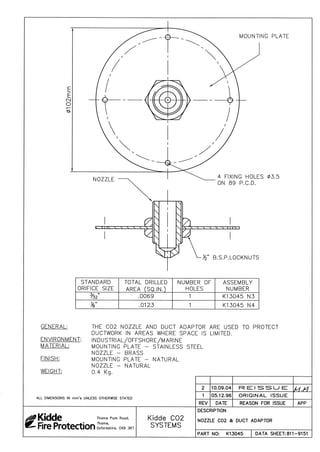
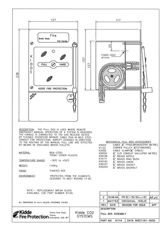
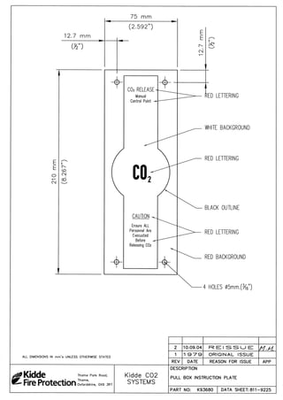
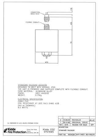
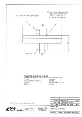
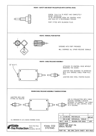
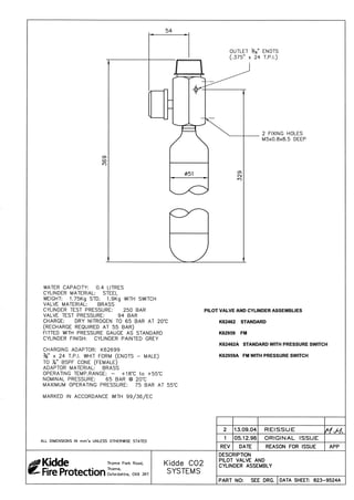
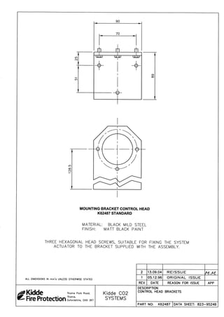
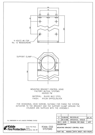
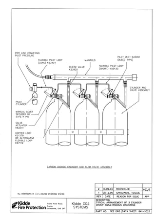
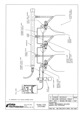
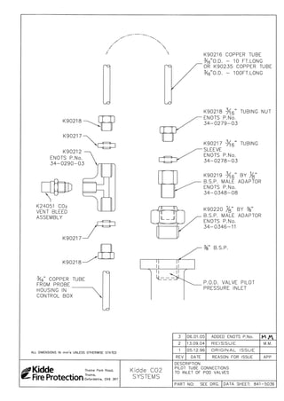

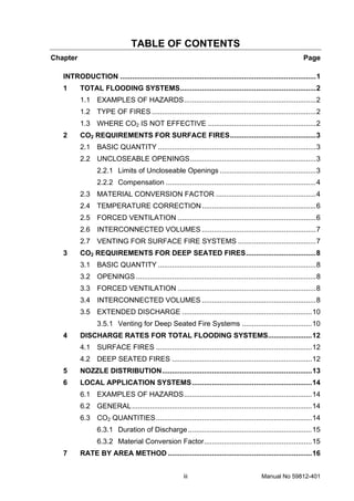
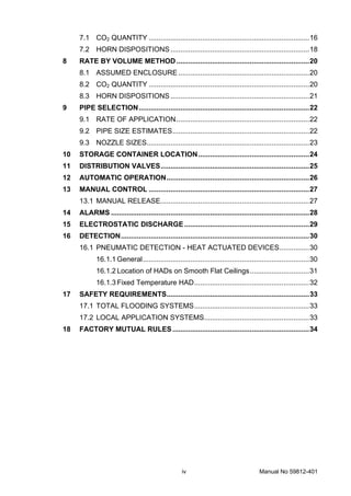


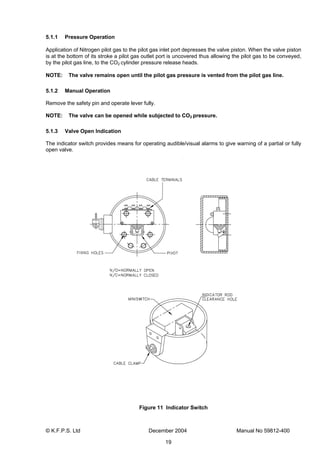
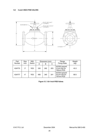
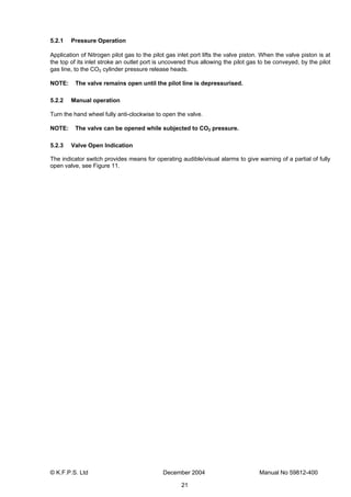
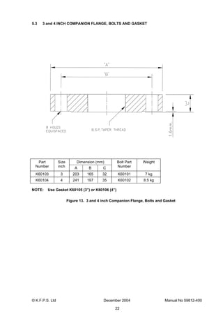
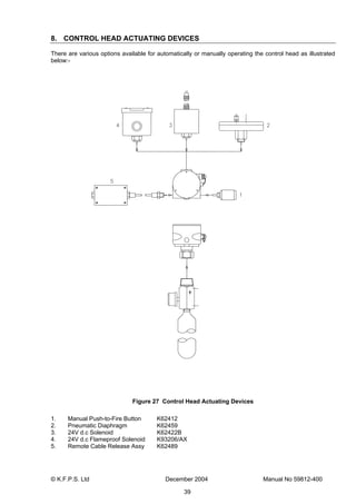
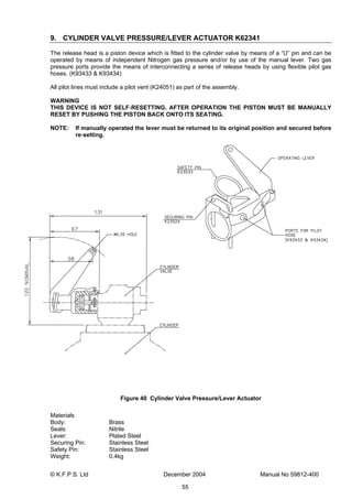
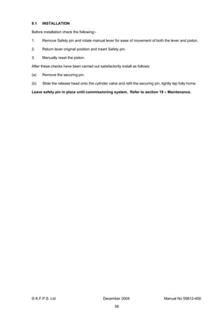
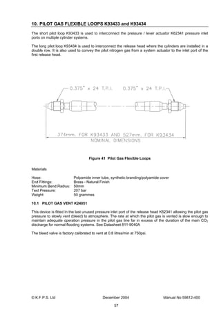
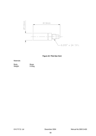

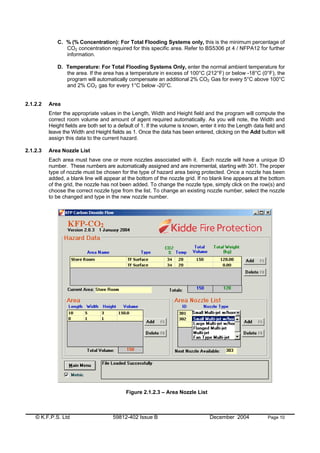
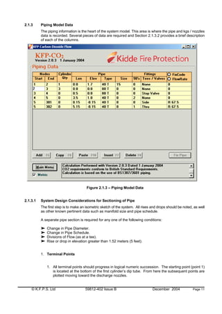
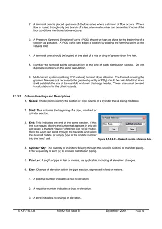
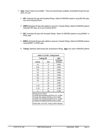
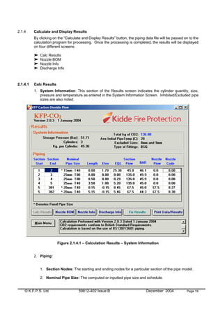
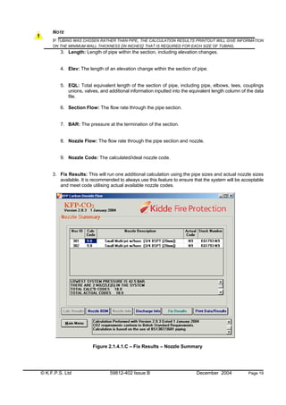
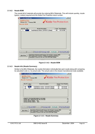
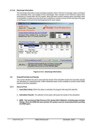
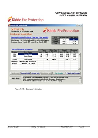
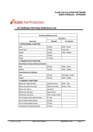


This document contains a product manual for a high pressure carbon dioxide fire suppression system. It includes 10 sections that cover specifications, data sheets, design manuals, installation manuals, software manuals, weight monitoring systems, solenoid valves, owner's manuals, approvals, and information bulletins. The document provides detailed information on the components, design, installation, and operation of Kidde carbon dioxide fire suppression systems.


![Rzeznik.wedliniarz 741[03] z4.02_u](https://cdn.slidesharecdn.com/ss_thumbnails/rzeznik-180314100920-thumbnail.jpg?width=640&height=640&fit=bounds)
![Rzeznik.wedliniarz 741[03] z1.02_u](https://cdn.slidesharecdn.com/ss_thumbnails/rzeznik-180314100835-thumbnail.jpg?width=640&height=640&fit=bounds)
![Temat 7 -_zadania_strazakow_w_zastepie_[prezentacja]](https://cdn.slidesharecdn.com/ss_thumbnails/temat7-zadaniastrazakowwzastepieprezentacja-150306042220-conversion-gate01-thumbnail.jpg?width=640&height=640&fit=bounds)


![Dietetyk 321[11] z2.06_u](https://cdn.slidesharecdn.com/ss_thumbnails/dietetyk32111z2-161022214232-thumbnail.jpg?width=640&height=640&fit=bounds)


![Technik.zywienia.i.gospodarstwa.domowego 321[10] z1.03_u](https://cdn.slidesharecdn.com/ss_thumbnails/technik-180314115439-thumbnail.jpg?width=640&height=640&fit=bounds)


