SlideShare a Scribd company logo
1 of 7
Download to read offline
The Materials That Make the Liquid Fluoride- Thorium Reactor Groundbreaking 
By Justin Carpenter 
Abstract 
This report will discuss some of the materials used in the Liquid Fluoride-Thorium Reactor which makes it unique from other nuclear reactors. The special aspects of the heat exchanger, thorium molten salt fuel, freeze plug, and emergency dump tank will be discussed. 
10/3/14 
ID# TUE71289 
Word count: 1,934
Introduction: 
One of the most extensive and complex scientific subjects is the search for safe and efficient energy. New types of power plants are being thought of and being built every year. On the cusp of nuclear technology are Liquid Fluoride-Thorium Reactor’s (Or LFTR’s). There currently are not any functioning reactors, but one is under construction in Alabama. This means that there currently aren’t any materials for a specific power plant, but there is a good amount of information regarding the new LFTR that is being built .The reactors work as a safer and cleaner alternative to current light-water nuclear reactors. LFTR’s use thorium dissolved in molten-salts, rather than solids, to produce more energy and at faster rate than a typical nuclear reactor. Special materials are needed in specific components of the plants to put up with the high temperatures and radiation. There are 4 specific components for LFTR’s that require special materials to function: the heat exchanger, freeze plug, emergency drop tank, and the molten thorium fuel. 
Heat Exchanger: 
The heat exchanger in the thorium cycle is used as an energy transfer mechanism to transfer energy from the molten-salt core into a gas which powers a turbine9. Heat is provided from the core to heat a gas inside of the exchanger. After the gas has passed through the turbine, it is then cooled and recycled. This means that temperatures of up to 2,400oC can occur in worst case scenarios, while also getting as low as room temperature. 
There are 2 specific types needed materials to withstand the constant change of temperatures. The inner wall of the exchanger is made of fiber-reinforced graphite able to withstand heat fluxes of up to 20MW/m2.5 The fibers form in the carbon-carbon are unidirectional, meaning that they have similar strength bonds in a pattern forming ultra-strong bonds in a lattice form10 as seen in figure 1. 
Figure 1. Lattice Structure of Graphite 
These bonds enable the graphite to withstand constant variations of extreme heat and pressures up to 19 Mpa11. The cycle is also performed without adding external pressure. This means that the pressure created in the heat exchanger is strictly from the reaction itself and not provided externally like traditional light water reactors (LWR’s). The benefit of having a structure that can withstand extreme
temperatures and pressure without the need of external reinforcements makes fiber-reinforced ideal for the base structure of the exchanger. 
The second material used to make the exchanger are a class of specialized alloys that provide strength and conduct heat in and out of the system. While the graphite (graphene) is used as a great structure to withstand the heat and pressure, a heat exchanger is still required to remove and transfer heat. Surrounding the graphite are metallic alloys that are used at heat sinks. These alloys are composed of tungsten, copper, and molybdenum5. These metals are ideal for manufacturing the heat sinks due to their ability to withstand extreme thermo-mechanical loads5. Once heat energy from the thorium core enters the heat exchanger, the energy is transferred through convection through the conductive alloys to another chamber where the gas is heated and used to power a turbine4. The equation for convection is provided below: 
Q*= HcA(Thot-Tcold) 
Equation 1: Heat transfer through conduction. 
Q* represents the total heat transfer, Hc represents the heat transfer coefficient per material, A is the cross-sectional area in contact, Thot is the temperature of the high energy source, and Tcold represents the temperature of the low energy source. While structures like graphene and graphite are ultra-strong and resistant, they lack the thermal conductive attributes needed for a heat exchanger. These alloys allow efficient heat transfer with minimal energy loss and are strong enough to withstand the thermo- mechanical loads12. 
Thorium Fuel: 
LFTR’s are special because they use a special fuel. One of the properties needed in general for an energy reactor is the ability to use as little fuel possible to obtain the maximum amount of energy. The thorium cycle is special because it has the potential for an endless reaction. The reaction starts with Th232, in which a thermal neutron strikes the atom and the Th232 atom “captures” it and transmutes into Th2333. With the half-life of Th233 being only 22 minutes, the atom decays into Protactinium-233 by releasing an electron and an anti neutrino3. After 27 days, the Pa-233 decays into U233 which is then separated from the thorium and protactinium and put back into the core and used as fissile material to provide the initial thermal neutron used in the initial thorium reaction3. The thorium can be “bred” twice and create a limitless reaction3. Only more thorium is needed to be added over time, but the reaction does not need to be stopped and started like most LWR’s. Below is Figure 2 with a detailed infographic regarding the reaction.
Figure 2. Schematic summarizing the f LFTR reaction3 
One of the major benefits of using this fuel is the fact that it is a liquid when mixed with molten salts mostly containing fluorine. Fluorine does not react with the thorium, protactinium, and uranium, which are a part of the main fissile reaction7. When at the temperature that the reaction is taking place at, Fluorine acts as a liquid and can be easily separated from the reactive materials7. This give the reactor an advantage because liquids are much easier to breakdown than a solid3. It takes greater energy to break down a solid due to its rigid molecular structure. When liquid fuels are used, the reaction can happen much faster and does not have to be put under pressure7. 
The salt solution that the thorium and Uranium are dissolved in is composed of mostly Fluorine, some Beryllium and a small amount of Lithium. It is maintained at about 600oC and atmospheric pressure3. It also acts as a coolant for the core, making it safer during operation3. The salt mixture is not consumed by the reaction, meaning that no energy, outside of the heat exchanger, is needed to cool the solution or even provide more salt to cool the solution, as you never lose any3. The reactor also runs at a very high temperature (roughly between 600-900 degrees Celsius), meaning that the thorium fuel solution is far more efficient at producing energy than the typical LWR’s that use solid fuels3. 
Freeze Plug: 
The freeze plug for the LFTR works as the main safety mechanism for the core. For normal LWR’s, zirconium rods are placed into the core of the reactor to act as cooling for the reaction using water as a heat sink7. This method is imperfect because the reaction happening in the core could gain too much heat and cause a meltdown, in which the cooling rods melt and drip onto the walls of the core and create a hole, leaking nuclear material7. Because the LFTR core is a liquid-salt mixture, this enables opportunities for different types of fail-safes. The LFTR utilizes a freeze plug kept at roughly 200 degrees Celsius in solid form. A fan cools the pipe and plug to keep it at a “frozen” temperature.
At the bottom of the tank that is the core, there is a pipe that leads to an emergency drain tank below the surface7. The plug is made out of similar beryllium salts that are constantly cooled7. If the core were to overheat, then 2 things would occur. First, the core would get too hot and automatically shut off the cooling provided by the fan (typically between 600-10000C). The plug would then heat up to critical temperature, melt and drain into an emergency tank under the surface7. This also works as a failsafe for electrical failures. If the core overheating was not the problem, but instead the electrical system for the plant was shut off, then the fan would shut off, preventing the plug from cooling. The plug would then melt, the fuel would drop into the tank, and the fuel would get cooled and have all of the dangerous neutrons absorbed. 
The salts used in the plug are non-reactive, meaning that even if the plug was in liquid form it would not react or create adverse effects with the thorium fuel. This is beneficial due to the fact that if the plug melts and everything drains into the emergency tank, the materials from the plug can be separated and reformed as a plug. 
Emergency Tank: 
The greatest concern about nuclear energy is the safety. Nuclear reactors mostly have negative public opinions. To make an optimum nuclear reactor, it must be safe and not prone to nuclear disasters. Paired with the freeze plug, the emergency tank is the feature which makes the LFTR safer than any reactor. When the electrical systems shut off or the reaction inside of the core gets too hot, the plug melts and the contents of the core flow into the emergency tank9. With the core not being pressurized, the emergency tank does not need to be pressurized either9. Below is a figure for a representation of how the emergency tank is related to the reactor as a whole. 
Figure 3. Relation of emergency tank to reactor4
When an emergency happens, the thorium fuel draining is very hot from the reaction. A perfect tank for this scenario would be made out of materials that handle the hottest that the fuel could get, and cool as quickly as possible without using extra energy3. The tank is made out of non-conductive alloys to retain heat and remain structurally intact when the thorium fuel comes rushing in. There is a system of heat exchangers (similar to the one talked about previously) above the tank that act as cooling rods3. 
Although the thorium fuel is chemically stable, the reaction still needs to be stopped when it drains into the tank. The tank is filled with neutron absorbers in the form of salts. These salts act as a quick damper to the nuclear reaction and turn the fuel into a solid14. The benefit of having the neutron absorbers in the bottom of the tank is not only to stop the reaction, but block the minimal harmful radiation that might come from the byproducts of the reaction14. The fuel is then able to be extracted later and restarted in the core once all problems are fixed14. 
Conclusion: 
Energy is one of the most talked about topics in the engineering world. Even though the first Liquid Fluoride-Thorium Reactor isn’t set to be up and running until 2015, and there isn’t a plethora of technical information, it shows how far nuclear reactor technology has come in the past 30 years. The LFTR creates opportunities for greater energy efficiency, reusable energy, and safer nuclear facilities that have a near negligible chance of melting down by using simple materials such as thorium, alloys, and molten-salts.
References 
1Huntsville Newswire, http://www.huntsvillenewswire.com/2011/09/27/huntsville-company-build- thoriumbased-nuclear-reactors/ 
2Thorium Energy Alliance, http://www.thoriumenergyalliance.com/downloads/TEAC3%20presentations/TEAC3_LeBlanc_David.pdf 
32112 Design Blog, http://www.2112design.com/blog/lftr/ 
4Wordpress.com, http://daryanenergyblog.wordpress.com/ca/part-8-msr-lftr/ 
5Plansee.com, http://www.plansee.com/en/Products-System-components-and-accessories-Nuclear- fusion-791.htm 
6World-Nuclear.org, http://www.world-nuclear.org/info/current-and-future-generation/thorium/ 
7Glerner.com, http://liquidfluoridethoriumreactor.glerner.com/2012-lftrs-have-no-chance-of-nuclear- meltdown/ 
8Triplepundent.com, http://www.triplepundit.com/2012/04/liquid-fluoride-thorium-power-pros-cons/ 
9Thorium Singapore, http://thoriumsingapore.com/content/index.php?option=com_content&view=article&id=50&Itemid=37 
10High Performance Carbon-Carbon composites, Lalit M Manocha, http://www.ias.ac.in/sadhana/Pdf2003Apr/Pe1069.pdf 
11Properties of reinforced Carbon, http://phycomp.technion.ac.il/~talimu/graphite_vacancy.bmp 
12Improved ODS Alloy for Heat Exchanger Tubing, http://www.netl.doe.gov/File%20Library/Events/2002/materials/harper.pdf 
13Tutorvista.com, http://formulas.tutorvista.com/physics/heat-transfer-formula.html 
14 http://lftrsuk.blogspot.com/p/benefits-of-lftrs.html 
Figures not from references above: 
http://www.spmtips.com/uploads/gallery/HOPG-structure-20121016071004.gif

More Related Content

What's hot

Presentation on electric induction furnace by Stead fast engineers Pvt Ltd
Presentation on electric induction furnace by Stead fast engineers Pvt LtdPresentation on electric induction furnace by Stead fast engineers Pvt Ltd
Presentation on electric induction furnace by Stead fast engineers Pvt Ltdsteadfast123
 
Simulation and Results of Static Var Compensator for Electric Arc Furnace No ...
Simulation and Results of Static Var Compensator for Electric Arc Furnace No ...Simulation and Results of Static Var Compensator for Electric Arc Furnace No ...
Simulation and Results of Static Var Compensator for Electric Arc Furnace No ...ijtsrd
 
Nuclear Fission
Nuclear FissionNuclear Fission
Nuclear Fissionstooty s
 
Nuclear reactors to produce electricity
Nuclear reactors to produce electricityNuclear reactors to produce electricity
Nuclear reactors to produce electricityWishal Butt
 
Nuclear power plant
Nuclear power plantNuclear power plant
Nuclear power plantAmol Kokare
 
NPP, Nuclear Power Plant,
NPP, Nuclear Power Plant, NPP, Nuclear Power Plant,
NPP, Nuclear Power Plant, Abha Tripathi
 
Nuclear Power Plant
Nuclear Power PlantNuclear Power Plant
Nuclear Power Plantmaneesh001
 
Types of Nuclear Reactor
Types of Nuclear ReactorTypes of Nuclear Reactor
Types of Nuclear ReactorNishit Desai
 
Nuclear reactors
Nuclear reactorsNuclear reactors
Nuclear reactorsNisarg Shah
 
Nuclear power plant
Nuclear power plantNuclear power plant
Nuclear power plantAakash Gupta
 
Lec-Nuclear-2.pptx
Lec-Nuclear-2.pptxLec-Nuclear-2.pptx
Lec-Nuclear-2.pptxWajidahmdani
 
Presentation presentation1.pptx nuclear_power_plant_me_1472237864_228826
Presentation presentation1.pptx nuclear_power_plant_me_1472237864_228826Presentation presentation1.pptx nuclear_power_plant_me_1472237864_228826
Presentation presentation1.pptx nuclear_power_plant_me_1472237864_228826jaymanek1
 
Nuclear reactor seminar
Nuclear reactor seminarNuclear reactor seminar
Nuclear reactor seminarMahesh Patil
 
Nuclear Fuel Cycle
Nuclear Fuel CycleNuclear Fuel Cycle
Nuclear Fuel CycleAyeman Mazdi
 
Industrial furnace manufacturers – Most popular choice for your industrial ap...
Industrial furnace manufacturers – Most popular choice for your industrial ap...Industrial furnace manufacturers – Most popular choice for your industrial ap...
Industrial furnace manufacturers – Most popular choice for your industrial ap...Shivang Furnace
 
nuclear powerplant ppt
nuclear powerplant pptnuclear powerplant ppt
nuclear powerplant pptRakesh Amanta
 

What's hot (20)

Presentation on electric induction furnace by Stead fast engineers Pvt Ltd
Presentation on electric induction furnace by Stead fast engineers Pvt LtdPresentation on electric induction furnace by Stead fast engineers Pvt Ltd
Presentation on electric induction furnace by Stead fast engineers Pvt Ltd
 
Simulation and Results of Static Var Compensator for Electric Arc Furnace No ...
Simulation and Results of Static Var Compensator for Electric Arc Furnace No ...Simulation and Results of Static Var Compensator for Electric Arc Furnace No ...
Simulation and Results of Static Var Compensator for Electric Arc Furnace No ...
 
Nuclear Fission
Nuclear FissionNuclear Fission
Nuclear Fission
 
Nuclear reactors to produce electricity
Nuclear reactors to produce electricityNuclear reactors to produce electricity
Nuclear reactors to produce electricity
 
Nuclear Materials
Nuclear MaterialsNuclear Materials
Nuclear Materials
 
Nuclear power plant
Nuclear power plantNuclear power plant
Nuclear power plant
 
NPP, Nuclear Power Plant,
NPP, Nuclear Power Plant, NPP, Nuclear Power Plant,
NPP, Nuclear Power Plant,
 
Nuclear Power Plant
Nuclear Power PlantNuclear Power Plant
Nuclear Power Plant
 
Nuclear technology
Nuclear technologyNuclear technology
Nuclear technology
 
Types of Nuclear Reactor
Types of Nuclear ReactorTypes of Nuclear Reactor
Types of Nuclear Reactor
 
Nuclear reactors
Nuclear reactorsNuclear reactors
Nuclear reactors
 
Nuclear power plant
Nuclear power plantNuclear power plant
Nuclear power plant
 
Lec-Nuclear-2.pptx
Lec-Nuclear-2.pptxLec-Nuclear-2.pptx
Lec-Nuclear-2.pptx
 
Nuclear power plant
Nuclear power plant Nuclear power plant
Nuclear power plant
 
Presentation presentation1.pptx nuclear_power_plant_me_1472237864_228826
Presentation presentation1.pptx nuclear_power_plant_me_1472237864_228826Presentation presentation1.pptx nuclear_power_plant_me_1472237864_228826
Presentation presentation1.pptx nuclear_power_plant_me_1472237864_228826
 
Nuclear reactor seminar
Nuclear reactor seminarNuclear reactor seminar
Nuclear reactor seminar
 
Nuclear Power
Nuclear PowerNuclear Power
Nuclear Power
 
Nuclear Fuel Cycle
Nuclear Fuel CycleNuclear Fuel Cycle
Nuclear Fuel Cycle
 
Industrial furnace manufacturers – Most popular choice for your industrial ap...
Industrial furnace manufacturers – Most popular choice for your industrial ap...Industrial furnace manufacturers – Most popular choice for your industrial ap...
Industrial furnace manufacturers – Most popular choice for your industrial ap...
 
nuclear powerplant ppt
nuclear powerplant pptnuclear powerplant ppt
nuclear powerplant ppt
 

Viewers also liked

Viewers also liked (11)

Presentation1
Presentation1Presentation1
Presentation1
 
7+1 myths of the new os
7+1 myths of the new os7+1 myths of the new os
7+1 myths of the new os
 
Resume_Alok
Resume_AlokResume_Alok
Resume_Alok
 
Um Estudo sobre Lógica Modal
Um Estudo sobre Lógica ModalUm Estudo sobre Lógica Modal
Um Estudo sobre Lógica Modal
 
Rpt bm tahun 3 2015
Rpt bm tahun 3 2015Rpt bm tahun 3 2015
Rpt bm tahun 3 2015
 
Sustaining the Knowledge Commons_Morrison et al CASRAI 2014
Sustaining the Knowledge Commons_Morrison et al CASRAI 2014Sustaining the Knowledge Commons_Morrison et al CASRAI 2014
Sustaining the Knowledge Commons_Morrison et al CASRAI 2014
 
Bab1
Bab1Bab1
Bab1
 
Ayie
AyieAyie
Ayie
 
Tablas funciones y gráficos
Tablas funciones y gráficosTablas funciones y gráficos
Tablas funciones y gráficos
 
Grafica12
Grafica12Grafica12
Grafica12
 
Informatica 2
Informatica 2Informatica 2
Informatica 2
 

Similar to JustinCarpenterLFTRMatSci

LMFBR - Superphenix
LMFBR - SuperphenixLMFBR - Superphenix
LMFBR - SuperphenixHossam Zein
 
Nuclear_power_plant.pdf
Nuclear_power_plant.pdfNuclear_power_plant.pdf
Nuclear_power_plant.pdfMemoonaShahid9
 
Sheraz assignment ppt
Sheraz assignment pptSheraz assignment ppt
Sheraz assignment pptumairkhan119
 
ThorCon CEO Explain Design [ICENES 2019]
ThorCon CEO Explain Design [ICENES 2019]ThorCon CEO Explain Design [ICENES 2019]
ThorCon CEO Explain Design [ICENES 2019]Bob Soelaiman Effendi
 
The Fukushima Daiichi Nuclear Plant
The Fukushima Daiichi Nuclear PlantThe Fukushima Daiichi Nuclear Plant
The Fukushima Daiichi Nuclear Plantsirdanielbilbruck
 
178875555 fast-breeder-reactors-pdf
178875555 fast-breeder-reactors-pdf178875555 fast-breeder-reactors-pdf
178875555 fast-breeder-reactors-pdfmanojg1990
 
electric arc furnace
electric arc furnaceelectric arc furnace
electric arc furnaceSanjitDhar
 
Heat transfer applications in oil and gas industry
Heat transfer applications in oil and gas industry Heat transfer applications in oil and gas industry
Heat transfer applications in oil and gas industry abdulsamad alhamawande
 
Overview Of Reactors
Overview Of ReactorsOverview Of Reactors
Overview Of ReactorsPrashant Jain
 
251153278 fast-breeder-reactors
251153278 fast-breeder-reactors251153278 fast-breeder-reactors
251153278 fast-breeder-reactorsmanojg1990
 
Heat Transfer Analysis to Optimize The Water Cooling Scheme For Combustion De...
Heat Transfer Analysis to Optimize The Water Cooling Scheme For Combustion De...Heat Transfer Analysis to Optimize The Water Cooling Scheme For Combustion De...
Heat Transfer Analysis to Optimize The Water Cooling Scheme For Combustion De...IJERA Editor
 

Similar to JustinCarpenterLFTRMatSci (20)

LMFBR - Superphenix
LMFBR - SuperphenixLMFBR - Superphenix
LMFBR - Superphenix
 
Nuclear_power_plant.pdf
Nuclear_power_plant.pdfNuclear_power_plant.pdf
Nuclear_power_plant.pdf
 
Sheraz assignment ppt
Sheraz assignment pptSheraz assignment ppt
Sheraz assignment ppt
 
ThorCon CEO Explain Design [ICENES 2019]
ThorCon CEO Explain Design [ICENES 2019]ThorCon CEO Explain Design [ICENES 2019]
ThorCon CEO Explain Design [ICENES 2019]
 
The Fukushima Daiichi Nuclear Plant
The Fukushima Daiichi Nuclear PlantThe Fukushima Daiichi Nuclear Plant
The Fukushima Daiichi Nuclear Plant
 
Better and faster
Better and fasterBetter and faster
Better and faster
 
Unit-3_PPE.pdf
Unit-3_PPE.pdfUnit-3_PPE.pdf
Unit-3_PPE.pdf
 
178875555 fast-breeder-reactors-pdf
178875555 fast-breeder-reactors-pdf178875555 fast-breeder-reactors-pdf
178875555 fast-breeder-reactors-pdf
 
NUCLEAR FUSION
NUCLEAR FUSIONNUCLEAR FUSION
NUCLEAR FUSION
 
Fusion rector
Fusion rectorFusion rector
Fusion rector
 
electric arc furnace
electric arc furnaceelectric arc furnace
electric arc furnace
 
Heat transfer applications in oil and gas industry
Heat transfer applications in oil and gas industry Heat transfer applications in oil and gas industry
Heat transfer applications in oil and gas industry
 
power1
power1power1
power1
 
Nuclear power plant
Nuclear power plantNuclear power plant
Nuclear power plant
 
Overview Of Reactors
Overview Of ReactorsOverview Of Reactors
Overview Of Reactors
 
251153278 fast-breeder-reactors
251153278 fast-breeder-reactors251153278 fast-breeder-reactors
251153278 fast-breeder-reactors
 
Nuclear power plant
Nuclear power plantNuclear power plant
Nuclear power plant
 
H48076265
H48076265H48076265
H48076265
 
Heat Transfer Analysis to Optimize The Water Cooling Scheme For Combustion De...
Heat Transfer Analysis to Optimize The Water Cooling Scheme For Combustion De...Heat Transfer Analysis to Optimize The Water Cooling Scheme For Combustion De...
Heat Transfer Analysis to Optimize The Water Cooling Scheme For Combustion De...
 
Tho
ThoTho
Tho
 

JustinCarpenterLFTRMatSci

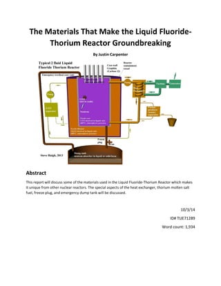
  • 1. The Materials That Make the Liquid Fluoride- Thorium Reactor Groundbreaking By Justin Carpenter Abstract This report will discuss some of the materials used in the Liquid Fluoride-Thorium Reactor which makes it unique from other nuclear reactors. The special aspects of the heat exchanger, thorium molten salt fuel, freeze plug, and emergency dump tank will be discussed. 10/3/14 ID# TUE71289 Word count: 1,934
  • 2. Introduction: One of the most extensive and complex scientific subjects is the search for safe and efficient energy. New types of power plants are being thought of and being built every year. On the cusp of nuclear technology are Liquid Fluoride-Thorium Reactor’s (Or LFTR’s). There currently are not any functioning reactors, but one is under construction in Alabama. This means that there currently aren’t any materials for a specific power plant, but there is a good amount of information regarding the new LFTR that is being built .The reactors work as a safer and cleaner alternative to current light-water nuclear reactors. LFTR’s use thorium dissolved in molten-salts, rather than solids, to produce more energy and at faster rate than a typical nuclear reactor. Special materials are needed in specific components of the plants to put up with the high temperatures and radiation. There are 4 specific components for LFTR’s that require special materials to function: the heat exchanger, freeze plug, emergency drop tank, and the molten thorium fuel. Heat Exchanger: The heat exchanger in the thorium cycle is used as an energy transfer mechanism to transfer energy from the molten-salt core into a gas which powers a turbine9. Heat is provided from the core to heat a gas inside of the exchanger. After the gas has passed through the turbine, it is then cooled and recycled. This means that temperatures of up to 2,400oC can occur in worst case scenarios, while also getting as low as room temperature. There are 2 specific types needed materials to withstand the constant change of temperatures. The inner wall of the exchanger is made of fiber-reinforced graphite able to withstand heat fluxes of up to 20MW/m2.5 The fibers form in the carbon-carbon are unidirectional, meaning that they have similar strength bonds in a pattern forming ultra-strong bonds in a lattice form10 as seen in figure 1. Figure 1. Lattice Structure of Graphite These bonds enable the graphite to withstand constant variations of extreme heat and pressures up to 19 Mpa11. The cycle is also performed without adding external pressure. This means that the pressure created in the heat exchanger is strictly from the reaction itself and not provided externally like traditional light water reactors (LWR’s). The benefit of having a structure that can withstand extreme
  • 3. temperatures and pressure without the need of external reinforcements makes fiber-reinforced ideal for the base structure of the exchanger. The second material used to make the exchanger are a class of specialized alloys that provide strength and conduct heat in and out of the system. While the graphite (graphene) is used as a great structure to withstand the heat and pressure, a heat exchanger is still required to remove and transfer heat. Surrounding the graphite are metallic alloys that are used at heat sinks. These alloys are composed of tungsten, copper, and molybdenum5. These metals are ideal for manufacturing the heat sinks due to their ability to withstand extreme thermo-mechanical loads5. Once heat energy from the thorium core enters the heat exchanger, the energy is transferred through convection through the conductive alloys to another chamber where the gas is heated and used to power a turbine4. The equation for convection is provided below: Q*= HcA(Thot-Tcold) Equation 1: Heat transfer through conduction. Q* represents the total heat transfer, Hc represents the heat transfer coefficient per material, A is the cross-sectional area in contact, Thot is the temperature of the high energy source, and Tcold represents the temperature of the low energy source. While structures like graphene and graphite are ultra-strong and resistant, they lack the thermal conductive attributes needed for a heat exchanger. These alloys allow efficient heat transfer with minimal energy loss and are strong enough to withstand the thermo- mechanical loads12. Thorium Fuel: LFTR’s are special because they use a special fuel. One of the properties needed in general for an energy reactor is the ability to use as little fuel possible to obtain the maximum amount of energy. The thorium cycle is special because it has the potential for an endless reaction. The reaction starts with Th232, in which a thermal neutron strikes the atom and the Th232 atom “captures” it and transmutes into Th2333. With the half-life of Th233 being only 22 minutes, the atom decays into Protactinium-233 by releasing an electron and an anti neutrino3. After 27 days, the Pa-233 decays into U233 which is then separated from the thorium and protactinium and put back into the core and used as fissile material to provide the initial thermal neutron used in the initial thorium reaction3. The thorium can be “bred” twice and create a limitless reaction3. Only more thorium is needed to be added over time, but the reaction does not need to be stopped and started like most LWR’s. Below is Figure 2 with a detailed infographic regarding the reaction.
  • 4. Figure 2. Schematic summarizing the f LFTR reaction3 One of the major benefits of using this fuel is the fact that it is a liquid when mixed with molten salts mostly containing fluorine. Fluorine does not react with the thorium, protactinium, and uranium, which are a part of the main fissile reaction7. When at the temperature that the reaction is taking place at, Fluorine acts as a liquid and can be easily separated from the reactive materials7. This give the reactor an advantage because liquids are much easier to breakdown than a solid3. It takes greater energy to break down a solid due to its rigid molecular structure. When liquid fuels are used, the reaction can happen much faster and does not have to be put under pressure7. The salt solution that the thorium and Uranium are dissolved in is composed of mostly Fluorine, some Beryllium and a small amount of Lithium. It is maintained at about 600oC and atmospheric pressure3. It also acts as a coolant for the core, making it safer during operation3. The salt mixture is not consumed by the reaction, meaning that no energy, outside of the heat exchanger, is needed to cool the solution or even provide more salt to cool the solution, as you never lose any3. The reactor also runs at a very high temperature (roughly between 600-900 degrees Celsius), meaning that the thorium fuel solution is far more efficient at producing energy than the typical LWR’s that use solid fuels3. Freeze Plug: The freeze plug for the LFTR works as the main safety mechanism for the core. For normal LWR’s, zirconium rods are placed into the core of the reactor to act as cooling for the reaction using water as a heat sink7. This method is imperfect because the reaction happening in the core could gain too much heat and cause a meltdown, in which the cooling rods melt and drip onto the walls of the core and create a hole, leaking nuclear material7. Because the LFTR core is a liquid-salt mixture, this enables opportunities for different types of fail-safes. The LFTR utilizes a freeze plug kept at roughly 200 degrees Celsius in solid form. A fan cools the pipe and plug to keep it at a “frozen” temperature.
  • 5. At the bottom of the tank that is the core, there is a pipe that leads to an emergency drain tank below the surface7. The plug is made out of similar beryllium salts that are constantly cooled7. If the core were to overheat, then 2 things would occur. First, the core would get too hot and automatically shut off the cooling provided by the fan (typically between 600-10000C). The plug would then heat up to critical temperature, melt and drain into an emergency tank under the surface7. This also works as a failsafe for electrical failures. If the core overheating was not the problem, but instead the electrical system for the plant was shut off, then the fan would shut off, preventing the plug from cooling. The plug would then melt, the fuel would drop into the tank, and the fuel would get cooled and have all of the dangerous neutrons absorbed. The salts used in the plug are non-reactive, meaning that even if the plug was in liquid form it would not react or create adverse effects with the thorium fuel. This is beneficial due to the fact that if the plug melts and everything drains into the emergency tank, the materials from the plug can be separated and reformed as a plug. Emergency Tank: The greatest concern about nuclear energy is the safety. Nuclear reactors mostly have negative public opinions. To make an optimum nuclear reactor, it must be safe and not prone to nuclear disasters. Paired with the freeze plug, the emergency tank is the feature which makes the LFTR safer than any reactor. When the electrical systems shut off or the reaction inside of the core gets too hot, the plug melts and the contents of the core flow into the emergency tank9. With the core not being pressurized, the emergency tank does not need to be pressurized either9. Below is a figure for a representation of how the emergency tank is related to the reactor as a whole. Figure 3. Relation of emergency tank to reactor4
  • 6. When an emergency happens, the thorium fuel draining is very hot from the reaction. A perfect tank for this scenario would be made out of materials that handle the hottest that the fuel could get, and cool as quickly as possible without using extra energy3. The tank is made out of non-conductive alloys to retain heat and remain structurally intact when the thorium fuel comes rushing in. There is a system of heat exchangers (similar to the one talked about previously) above the tank that act as cooling rods3. Although the thorium fuel is chemically stable, the reaction still needs to be stopped when it drains into the tank. The tank is filled with neutron absorbers in the form of salts. These salts act as a quick damper to the nuclear reaction and turn the fuel into a solid14. The benefit of having the neutron absorbers in the bottom of the tank is not only to stop the reaction, but block the minimal harmful radiation that might come from the byproducts of the reaction14. The fuel is then able to be extracted later and restarted in the core once all problems are fixed14. Conclusion: Energy is one of the most talked about topics in the engineering world. Even though the first Liquid Fluoride-Thorium Reactor isn’t set to be up and running until 2015, and there isn’t a plethora of technical information, it shows how far nuclear reactor technology has come in the past 30 years. The LFTR creates opportunities for greater energy efficiency, reusable energy, and safer nuclear facilities that have a near negligible chance of melting down by using simple materials such as thorium, alloys, and molten-salts.
  • 7. References 1Huntsville Newswire, http://www.huntsvillenewswire.com/2011/09/27/huntsville-company-build- thoriumbased-nuclear-reactors/ 2Thorium Energy Alliance, http://www.thoriumenergyalliance.com/downloads/TEAC3%20presentations/TEAC3_LeBlanc_David.pdf 32112 Design Blog, http://www.2112design.com/blog/lftr/ 4Wordpress.com, http://daryanenergyblog.wordpress.com/ca/part-8-msr-lftr/ 5Plansee.com, http://www.plansee.com/en/Products-System-components-and-accessories-Nuclear- fusion-791.htm 6World-Nuclear.org, http://www.world-nuclear.org/info/current-and-future-generation/thorium/ 7Glerner.com, http://liquidfluoridethoriumreactor.glerner.com/2012-lftrs-have-no-chance-of-nuclear- meltdown/ 8Triplepundent.com, http://www.triplepundit.com/2012/04/liquid-fluoride-thorium-power-pros-cons/ 9Thorium Singapore, http://thoriumsingapore.com/content/index.php?option=com_content&view=article&id=50&Itemid=37 10High Performance Carbon-Carbon composites, Lalit M Manocha, http://www.ias.ac.in/sadhana/Pdf2003Apr/Pe1069.pdf 11Properties of reinforced Carbon, http://phycomp.technion.ac.il/~talimu/graphite_vacancy.bmp 12Improved ODS Alloy for Heat Exchanger Tubing, http://www.netl.doe.gov/File%20Library/Events/2002/materials/harper.pdf 13Tutorvista.com, http://formulas.tutorvista.com/physics/heat-transfer-formula.html 14 http://lftrsuk.blogspot.com/p/benefits-of-lftrs.html Figures not from references above: http://www.spmtips.com/uploads/gallery/HOPG-structure-20121016071004.gif