John deere power tech 2.9l diesel engine diagnostic service repair technical manual (ctm125)
1. CTM125 - PowerTech™ 2.9 LDiesel Engines
Install Valves
Install Valves
1. Apply engine oil to valve stems and guides.
2. Insert valves in head (in same location as found during removal).
NOTE:
Valves must move freely and seat properly.
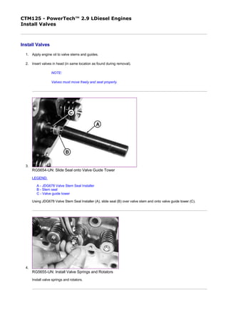
3.
RG5654-UN: Slide Seal onto Valve Guide Tower
LEGEND:
A - JDG678 Valve Stem Seal Installer
B - Stem seal
C - Valve guide tower
Using JDG678 Valve Stem Seal Installer (A), slide seal (B) over valve stem and onto valve guide tower (C).
4.
RG5655-UN: Install Valve Springs and Rotators
Install valve springs and rotators.
1/2
2019/12/27file:///C:/ProgramData/Service%20ADVISOR/Temp/CTM125_09001faa8010...
2. 5. Compress valve springs using JDE138 Valve Spring Compressor and install new keepers on valves.
CD30233-UN: Compress Valve Springs
NOTE:
After having installed the valves, strike end of each valve three times with a soft mallet to ensure
proper positioning of the keepers.
CD,3274,G05,21-19-20010105
2/2
2019/12/27file:///C:/ProgramData/Service%20ADVISOR/Temp/CTM125_09001faa8010...
3. CTM125 - PowerTech™ 2.9 LDiesel Engines
Install Cylinder Head
Install Cylinder Head
RG4718-UN: Install Cylinder Head
CD30693-UN: Cam Follower
1/3
2019/12/27file:///C:/ProgramData/Service%20ADVISOR/Temp/CTM125_09001faa8010...
4. CD30543-UN: Locating Holes
LEGEND:
A - Front of engine
B - Guide stud locations
C - Cam follower
1. Clean tapped holes in cylinder block using JDG680 Tap (or any 1/2-13 UNC-2A tap). Use compressed air to remove
debris or any fluids from cap screw holes.
2. IMPORTANT:
Insure that cam followers (C) are present before cylinder head installation.
Install new cylinder head gasket dry (without sealant)
3. IMPORTANT:
Without guide studs, the Viton O-ring attached to cylinder head gasket (at rocker arm lube oil passage)
could be damaged when repositioning cylinder head on engine block to align cap screw holes.
Install two guide studs in cylinder block at locating holes (B).
4. Position cylinder head over guide studs and lower into place on cylinder block.
5. NOTE:
Always use new cap screws to install cylinder head.
Dip new cap screws entirely in clean engine oil.
6. Remove guide studs and install cap screws in all open bores.
7. Tighten cap screws in sequence to the torque specified, beginning with No. 1, then torque turn to specified angle. Use
JD-307 Torque Wrench Adapter if necessary.
Item Measurement Specification
Cylinder head bolts
1st step Torque 100 N˙m (75 lb-ft)
2/3
2019/12/27file:///C:/ProgramData/Service%20ADVISOR/Temp/CTM125_09001faa8010...
6. CTM125 - PowerTech™ 2.9 LDiesel Engines
Torque Turn Tightening Method
Torque Turn Tightening Method
RG5698-UN: JT05993 Torque Angle Gauge
CD30797-UN: Line Scribe Torque Turn Method
LEGEND:
A - Reference mark
B - 60° mark
After tightening cap screws to 150 N˙m (110 lb-ft), use JT05993 Torque Angle Gauge or the line scribble method below to
tighten each cap screw an additional 60° angle.
1/2
2019/12/27file:///C:/ProgramData/Service%20ADVISOR/Temp/CTM125_09001faa8010...
7. Line scribe method:
1. Make a mark on socket and make a second mark 60° counterclockwise from the first.
2. Make a mark on cylinder head next to each cap screw.
3. Place socket on cap screw so that first mark aligns with mark on cylinder head.
4. Tighten (in sequence) all cap screws until second mark on socket aligns with mark on cylinder head.
NOTE:
The torque turn method eliminates the need to retorque the cylinder head bolts after the first hours of
engine operation. However, valve clearance adjustment is still required.
CD,CTM125,035-19-20000403
2/2
2019/12/27file:///C:/ProgramData/Service%20ADVISOR/Temp/CTM125_09001faa8010...
8. CTM125 - PowerTech™ 2.9 LDiesel Engines
Disassembling and Checking Rocker Arm Shaft
Disassembling and Checking Rocker Arm Shaft
CD30799-UN: Checking rocker arm shaft (1)
CD30800-UN: Checking rocker arm shaft (2)
LEGEND:
A - Rocker arm shaft
B - Support
C - Plug
D - Cap screw
E - Washer
F - Bowed washer
G - Oil supply hole in rocker arm shaft
H - Oil supply hole in cylinder head
1. Remove plugs (C) and bowed washers (F) from rocker arm shaft.
2. Slide springs, rocker arms and supports off rocker arm shaft, identifying their sequence for reassembly in the same
order.
3. Clean all parts with solvent and dry with compressed air.
4. Check all parts for good condition.
1/2
2019/12/27file:///C:/ProgramData/Service%20ADVISOR/Temp/CTM125_09001faa8010...
9. 5. Replace parts as necessary.
NOTE:
If the rocker arm has been damaged by a valve failure, replace it together with the corresponding
push rod, valve rotator and keepers.
Item Measurement Specification
Rocker arm
Shaft Diameter 19.99—20.02 mm (0.787—0.788 in.)
Wear tolerance 19.94 mm (0.785 in.)
Bore Diameter 20.07—20.12 mm (0.790—0.792 in.)
Wear tolerance 20.17 mm (0.784 in.)
Spring Load at 46 mm (1.81 in.)
compressed length
18—27 N (4—6 lb.)
CD,3274,G05,56-19-20010105
2/2
2019/12/27file:///C:/ProgramData/Service%20ADVISOR/Temp/CTM125_09001faa8010...
10. CTM125 - PowerTech™ 2.9 LDiesel Engines
Reassembling Rocker Arm Shaft
Reassembling Rocker Arm Shaft
CD30799-UN: Checking rocker arm shaft (1)
CD30800-UN: Checking rocker arm shaft (2)
LEGEND:
A - Rocker arm shaft
B - Support
C - Plug
D - Cap screw
E - Washer
F - Bowed washer
G - Oil supply hole in rocker arm shaft
H - Oil supply hole in cylinder head
NOTE:
Effective with following engine serial numbers, shaft (A) and cap screw (D) with washer (E) have been
replaced by a new shaft and flanged head cap screws.
-: Engine SN for new rocker arm shaft
Saran engines
1/2
2019/12/27file:///C:/ProgramData/Service%20ADVISOR/Temp/CTM125_09001faa8010...
11. These parts are not interchangeable except when using a conversion kit including shaft (A) + support
(B) + plug (C) + R504813 flanged head cap screws (D). Refer to appropriate Parts Catalog for more
details.
Some engines built after above engine serial numbers may have been assembled with the previous
19H3031 cap screws (non-flanged) and R42729 washers (E). In this case, when re-assembling this
engine, use the R504813 flanged head cap screws (without washer).
1. Lubricate shaft, bores of rocker arms and supports.
2. Slide springs, rocker arms and supports onto shaft. Assemble in the same order in which they were removed during
disassembly.
3. IMPORTANT:
The hole (G) in the shaft must be in line with the oil supply hole (H) of cylinder head.
Install bowed washers (F) and new plugs (C) on shaft.
394179CD (Non-Certified engines)
563950CD (Certified engines
Torreon engines
22965PE
CD03523,00000E4-19-20010108
2/2
2019/12/27file:///C:/ProgramData/Service%20ADVISOR/Temp/CTM125_09001faa8010...
12. Thank you very much for
your reading. Please Click
Here. Then Get COMPLETE
MANUAL. NO WAITING
NOTE:
If there is no response to
click on the link above,
please download the PDF
document first and then
click on it.
13. CTM125 - PowerTech™ 2.9 LDiesel Engines
Install Rocker Arm Assembly
Install Rocker Arm Assembly
CD30694-UN: Install Push Rods
1. Install push rods (A) in same location from which they were removed.
NOTE:
Valve stem tips are specially hardened, wear caps are not required.
2. Position rocker arm assembly on engine.
3. Lubricate the rocker arms with engine oil.
4. Tighten attaching cap screws to specifications.
Item Measurement Specification
Rocker arm support cap screw Torque 50 N˙m (35 lb-ft)
CD,CTM125,033-19-20010108
1/1
2019/12/27file:///C:/ProgramData/Service%20ADVISOR/Temp/CTM125_09001faa8010...
14. CTM125 - PowerTech™ 2.9 LDiesel Engines
Valve Clearance
Valve Clearance
CD30544-UN: Flywheel Turning Tool and Timing Pin
The valve clearance must be adjusted when engine is cold.
Using JDE83 or JDG820 Flywheel Turning Tool (A), rotate engine flywheel in running direction (clockwise viewed from water pump)
until No.1 piston (front) has reached top dead center (TDC) on compression stroke. Insert timing pin JDE81-4 or JDG1571 (B) into
flywheel bore.
NOTE:
When No. 1 piston is at TDC on compression stroke, valve springs of No. 1 cylinder are not under tension.
Adjust valve clearance as directed in the following block.
Item Measurement Specification
Intake Valve Clearance 0.35 mm (0.014 in.)
Exhaust Valve Clearance 0.45 mm (0.018 in.)
CD,CTM125,036-19-20040709
1/1
2019/12/27file:///C:/ProgramData/Service%20ADVISOR/Temp/CTM125_09001faa8010...
16. CD30549-UN: Valve Adjustment
LEGEND:
A - Front of engine
B - Exhaust valve
C - Intake valve
D - No. 1 piston at TDC compression stroke
E - No. 1 piston at TDC exhaust stroke
F - Rocker arm adjustment screw jam nut
1. Adjust valve clearance on No. 1 and 2 exhaust valves and No. 1 and 3 intake valves.
2. Turn crankshaft 360° and reinsert timing pin.
3. Adjust valve clearance on No. 3 exhaust valve and No. 2 intake valve.
Item Measurement Specification
Valve clearance Firing order 1-2-3
Rocker arm adjustment screw jam
nut (Later design)-Torque
30 N·m (25 lb-ft)
CD,CTM125,037-19-20040709
2/2
2019/12/27file:///C:/ProgramData/Service%20ADVISOR/Temp/CTM125_09001faa8010...