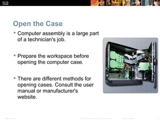
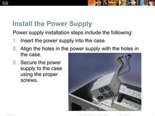
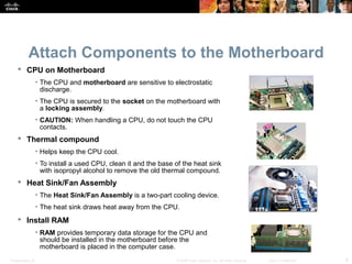
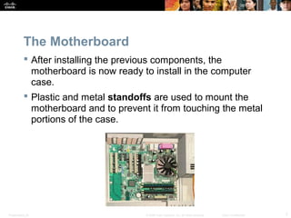
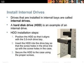
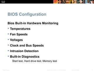
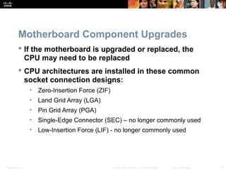
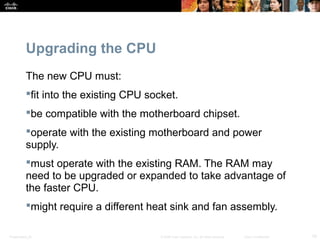
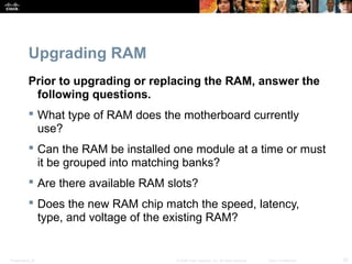
SlideShare a Scribd company logo
© 2008 Cisco Systems, Inc. All rights reserved. Cisco ConfidentialPresentation_ID 1
Chapter 3:
Computer Assembly
IT Essentials 5.0
Presentation_ID 2© 2008 Cisco Systems, Inc. All rights reserved. Cisco Confidential
Chapter 3 Objectives
 3.1.1 Open the case
 3.1.1 Install the power supply
 3.1.2 Attach the components to the motherboard and
install the motherboard
 3.1.3 Install internal drives and drives in external bays
 3.1.4 Install adapter cards
 3.1.5 Install and connect all internal cables
 3.1.5 Re-attach the side panels and connect external
cables to the computer
 3.2.1 Boot the computer for the first time
 3.2.2 Configure BIOS
Presentation_ID 3© 2008 Cisco Systems, Inc. All rights reserved. Cisco Confidential
Chapter 3 Objectives
 3.3 Describe reasons for upgrading computer
components
 3.3.1 Select and install replacement or upgraded
motherboard, CPU, heat sink and fan, and RAM
 3.3.1 Upgrade and configure BIOS
 3.3.2 Select and install replacement or upgraded hard
drives
 3.3.3 Select and install replacement or upgraded input
and output devices
Presentation_ID 4© 2008 Cisco Systems, Inc. All rights reserved. Cisco Confidential
Open the Case
 Computer assembly is a large part
of a technician's job.
 Prepare the workspace before
opening the computer case.
 There are different methods for
opening cases. Consult the user
manual or manufacturer's
website.
Presentation_ID 5© 2008 Cisco Systems, Inc. All rights reserved. Cisco Confidential
Install the Power Supply
Power supply installation steps include the following:
1. Insert the power supply into the case.
2. Align the holes in the power supply with the holes in
the case.
3. Secure the power
supply to the case
using the proper
screws.
Presentation_ID 6© 2008 Cisco Systems, Inc. All rights reserved. Cisco Confidential
Attach Components to the Motherboard
 CPU on Motherboard
• The CPU and motherboard are sensitive to electrostatic
discharge.
• The CPU is secured to the socket on the motherboard with
a locking assembly.
• CAUTION: When handling a CPU, do not touch the CPU
contacts.
 Thermal compound
• Helps keep the CPU cool.
• To install a used CPU, clean it and the base of the heat sink
with isopropyl alcohol to remove the old thermal compound.
 Heat Sink/Fan Assembly
• The Heat Sink/Fan Assembly is a two-part cooling device.
• The heat sink draws heat away from the CPU.
 Install RAM
• RAM provides temporary data storage for the CPU and
should be installed in the motherboard before the
motherboard is placed in the computer case.
Presentation_ID 7© 2008 Cisco Systems, Inc. All rights reserved. Cisco Confidential
The Motherboard
 After installing the previous components, the
motherboard is now ready to install in the computer
case.
 Plastic and metal standoffs are used to mount the
motherboard and to prevent it from touching the metal
portions of the case.
Presentation_ID 8© 2008 Cisco Systems, Inc. All rights reserved. Cisco Confidential
Install Internal Drives
 Drives that are installed in internal bays are called
internal drives.
 A hard disk drive (HDD) is an example of an
internal drive.
 HDD installation steps:
1. Position the HDD so that it aligns
with the 3.5-inch drive bay.
2. Insert the HDD into the drive bay so
that the screw holes in the drive line
up with the screw holes in the case.
3. Secure the HDD to the case using
the proper screws.
Presentation_ID 9© 2008 Cisco Systems, Inc. All rights reserved. Cisco Confidential
Install Drives in External Bays
 Drives in external bays allow access to the
media without opening the case.
 Some devices that are installed in this type
of drive are:
• An optical drive is a storage device
that reads and writes information to
CDs, DVDs, or BDs.
• A floppy disk drive (FDD) is a storage
device that reads and writes
information to a floppy disk.
Presentation_ID 10© 2008 Cisco Systems, Inc. All rights reserved. Cisco Confidential
Install Adapter Cards
 Adapter cards are installed to add functionality to a computer.
 Some examples of these adapters are:
• A Network Interface Card (NIC) which enables a computer to
connect to a network. It uses PCI and PCIe expansion slots on
the motherboard.
• A wireless NIC enables a computer to connect to a wireless
network. Wireless NICs use PCI and PCIe expansion slots on the
motherboard. Some wireless NICs are installed externally with a
USB connector.
• A video adapter card is the interface between a computer and a
display monitor. An upgraded video adapter card can provide
better graphic capabilities for games and graphic programs.
Video adapter cards use PCI, AGP, and PCIe expansion slots on
the motherboard.
Presentation_ID 11© 2008 Cisco Systems, Inc. All rights reserved. Cisco Confidential
Connect Internal Cables
 Power cables are used to distribute electricity from the
power supply to the motherboard and other components.
ATX
AUX BergSATA Molex
Presentation_ID 12© 2008 Cisco Systems, Inc. All rights reserved. Cisco Confidential
Connect Internal Cables
 Data cables transmit data between the motherboard and
storage devices, such as hard drives. Some of examples of
this type of cables are:
• PATA cable
• SATA cable
• Floppy drive data cable
 Additional cables connect the buttons and link lights on the
front of the computer case to the motherboard.
Presentation_ID 13© 2008 Cisco Systems, Inc. All rights reserved. Cisco Confidential
Complete Physical Installation
 Now that all the internal components and the power
supply have been installed and connected to the
motherboard, the following tasks should be
completed:
•Re-Attach the side panels: Most computer cases have
two panels, one on each side. Some computer cases
have one three-sided cover that slides down over the
case frame.
•Connect the External Cables: These cables are
normally connected to the back of the computer. Here are
some common external cable connections: Monitor,
Keyboard, Mouse, USB, Ethernet, Power.
Presentation_ID 14© 2008 Cisco Systems, Inc. All rights reserved. Cisco Confidential
Boot Computer for the First Time
 When the computer is booted, the basic input/output
system (BIOS) will perform a power-on self test (POST)
to check on all of the internal components.
 The BIOS contains a setup program used to configure
settings for hardware devices. The configuration data is
saved to a special memory chip called a
complementary metal-oxide semiconductor (CMOS)
or can be saved in nonvolatile memory which does
not need power to retain settings.
 POST checks to see that all of the hardware in the
computer is operating correctly. If a device is
malfunctioning, an error or a beep code alerts the
technician that there is a problem.
Presentation_ID 15© 2008 Cisco Systems, Inc. All rights reserved. Cisco Confidential
BIOS Configuration
 Technicians use the BIOS information to learn
about installed components:
• CPU – Manufacturer and speed
• RAM - Manufacturer and speed
• Hard Drive - Manufacturer, size, and type
• Optical Drive - manufacturer and type
 Technicians use BIOS to:
• Set Time and Date
• Disable Devices
• Set Boot Order
• Adjust Clock Speed
• Enable Virtualization
Presentation_ID 16© 2008 Cisco Systems, Inc. All rights reserved. Cisco Confidential
BIOS Configuration
 Technicians can set the following BIOS security
features
BIOS passwords
Drive encryption
Trusted Platform Module (TPM)
Lojack
• Lock the computer remotely.
• Display a message so that a lost computer can be returned to
the owner.
• Delete sensitive data on the computer if stolen.
• Locate the computer using geotechnology.
Presentation_ID 17© 2008 Cisco Systems, Inc. All rights reserved. Cisco Confidential
BIOS Configuration
Bios Built-in Hardware Monitoring
 Temperatures
 Fan Speeds
 Voltages
 Clock and Bus Speeds
 Intrusion Detection
 Built-in Diagnostics
Start test, Hard drive test, Memory test
Presentation_ID 18© 2008 Cisco Systems, Inc. All rights reserved. Cisco Confidential
Motherboard Component Upgrades
 If the motherboard is upgraded or replaced, the
CPU may need to be replaced
 CPU architectures are installed in these common
socket connection designs:
• Zero-Insertion Force (ZIF)
• Land Grid Array (LGA)
• Pin Grid Array (PGA)
• Single-Edge Connector (SEC) – no longer commonly used
• Low-Insertion Force (LIF) - no longer commonly used
Presentation_ID 19© 2008 Cisco Systems, Inc. All rights reserved. Cisco Confidential
Upgrading the CPU
The new CPU must:
fit into the existing CPU socket.
be compatible with the motherboard chipset.
operate with the existing motherboard and power
supply.
must operate with the existing RAM. The RAM may
need to be upgraded or expanded to take advantage of
the faster CPU.
might require a different heat sink and fan assembly.
Presentation_ID 20© 2008 Cisco Systems, Inc. All rights reserved. Cisco Confidential
Upgrading RAM
Prior to upgrading or replacing the RAM, answer the
following questions.
 What type of RAM does the motherboard currently
use?
 Can the RAM be installed one module at a time or must
it be grouped into matching banks?
 Are there available RAM slots?
 Does the new RAM chip match the speed, latency,
type, and voltage of the existing RAM?
Presentation_ID 21© 2008 Cisco Systems, Inc. All rights reserved. Cisco Confidential
BIOS
 Motherboard manufacturers periodically release
updates for their BIOS.
 Modern BIOS chips are EEPROM, or flash memory,
which can be upgraded by the user without opening the
computer case. This process is called flashing the
BIOS.
 Flash the BIOS through a command prompt.
 Several motherboard manufacturers provide software
that allow a user to flash the BIOS from within
Windows.
Presentation_ID 22© 2008 Cisco Systems, Inc. All rights reserved. Cisco Confidential
Storage Devices
Reasons for installing an additional drive:
• Install a second operating system
• Provide additional storage space
• Provide a faster hard drive
• Hold the system swap file
• Back up the original hard drive
• Increase fault tolerance
 When two PATA hard drives are connected to same
data cable, one drive must be jumpered as the master,
other drive must be jumpered as the slave drive.
 Each SATA hard drive has its own data cable, therefore,
there is no master-slave relationship between drives
Presentation_ID 23© 2008 Cisco Systems, Inc. All rights reserved. Cisco Confidential
RAID
 A Redundant Array of Independent Disks (RAID)
installation can provide data protection or increased
performance when connecting multiple hard drive.
Presentation_ID 24© 2008 Cisco Systems, Inc. All rights reserved. Cisco Confidential
Input and Output Devices
 Replacement and/ or upgrade examples:
•Change to an Ergonomic keyboard or mouse
•Add privacy and antiglare filters to a monitor
•Add additional monitors
 Use the existing expansion slots or sockets.
 May use a USB connection.
 Add USB connections by installing a USB adapter card
or add a USB hub.
 Install drivers if necessary.
Presentation_ID 25© 2008 Cisco Systems, Inc. All rights reserved. Cisco Confidential
Chapter 3 Summary
Computer Assembly
 Installation of all computer components
 Connection of all cables
 Description and configuration of BIOS
 Description of POST
Upgrading and Configuring a PC
 Motherboard and Related Components
 Storage Devices
 Input and Output devices
Presentation_ID 26© 2008 Cisco Systems, Inc. All rights reserved. Cisco Confidential

More Related Content

What's hot

POLITEKNIK MALAYSIA
POLITEKNIK MALAYSIAPOLITEKNIK MALAYSIA
POLITEKNIK MALAYSIA
Aiman Hud
 
Chipsets amd
Chipsets amdChipsets amd
Chipsets amd
abinegrete
 
Yashi dealer meeting settembre 2016 tecnologie xeon intel italia
Yashi dealer meeting settembre 2016 tecnologie xeon intel italiaYashi dealer meeting settembre 2016 tecnologie xeon intel italia
Yashi dealer meeting settembre 2016 tecnologie xeon intel italia
Yashi Italia
 
Ite v5.0 chapter1
Ite v5.0 chapter1Ite v5.0 chapter1
Ite v5.0 chapter1
Kazi Rafsun Shaanto
 
It Essentials (Version 7.0) A+ Cert Practice Exam 1 Answers
It Essentials (Version 7.0) A+ Cert Practice Exam 1 AnswersIt Essentials (Version 7.0) A+ Cert Practice Exam 1 Answers
It Essentials (Version 7.0) A+ Cert Practice Exam 1 Answers
ITExamAnswers.net
 
Dell Latitude E6430 Laptops Trần Phát
Dell Latitude E6430 Laptops Trần PhátDell Latitude E6430 Laptops Trần Phát
Dell Latitude E6430 Laptops Trần Phát
LAPTOP TRẦN PHÁT
 
IBM Redbooks Product Guide: IBM BladeCenter HS23E
IBM Redbooks Product Guide: IBM BladeCenter HS23EIBM Redbooks Product Guide: IBM BladeCenter HS23E
IBM Redbooks Product Guide: IBM BladeCenter HS23E
IBM India Smarter Computing
 
Gigabyte mb manual ga-q77m-d2h_e
Gigabyte mb manual ga-q77m-d2h_eGigabyte mb manual ga-q77m-d2h_e
Gigabyte mb manual ga-q77m-d2h_e
Anthony Wu
 
Ite v5.0 chapter4
Ite v5.0 chapter4Ite v5.0 chapter4
Ite v5.0 chapter4
Kazi Rafsun Shaanto
 
Ite pc v40_chapter1
Ite pc v40_chapter1Ite pc v40_chapter1
Ite pc v40_chapter1
paulinagonzapyl
 
Hp envy 13 2021 Laptops Trần Phát
Hp envy 13 2021 Laptops Trần PhátHp envy 13 2021 Laptops Trần Phát
Hp envy 13 2021 Laptops Trần Phát
LAPTOP TRẦN PHÁT
 
Ite pc v40_chapter2
Ite pc v40_chapter2Ite pc v40_chapter2
Ite pc v40_chapter2
paulinagonzapyl
 
Css grade 11 week 4
Css grade 11 week 4Css grade 11 week 4
Css grade 11 week 4
Danilo Anos
 
Fred server
Fred serverFred server
Fred server
Yansi Keim
 
Project on computer assembling
Project on computer assemblingProject on computer assembling
Project on computer assembling
Subhojit Paul
 
System configuration
System configurationSystem configuration
System configuration
Ayubu Churi
 
Mount Adams Lar
Mount Adams LarMount Adams Lar
Mount Adams Lar
guestdbf0cb
 
Dell XPS 9305: Ultrabook 13 inch mới nhất của Dell
Dell XPS 9305: Ultrabook 13 inch mới nhất của Dell Dell XPS 9305: Ultrabook 13 inch mới nhất của Dell
Dell XPS 9305: Ultrabook 13 inch mới nhất của Dell
LAPTOP TRẦN PHÁT
 

What's hot (18)

POLITEKNIK MALAYSIA
POLITEKNIK MALAYSIAPOLITEKNIK MALAYSIA
POLITEKNIK MALAYSIA
 
Chipsets amd
Chipsets amdChipsets amd
Chipsets amd
 
Yashi dealer meeting settembre 2016 tecnologie xeon intel italia
Yashi dealer meeting settembre 2016 tecnologie xeon intel italiaYashi dealer meeting settembre 2016 tecnologie xeon intel italia
Yashi dealer meeting settembre 2016 tecnologie xeon intel italia
 
Ite v5.0 chapter1
Ite v5.0 chapter1Ite v5.0 chapter1
Ite v5.0 chapter1
 
It Essentials (Version 7.0) A+ Cert Practice Exam 1 Answers
It Essentials (Version 7.0) A+ Cert Practice Exam 1 AnswersIt Essentials (Version 7.0) A+ Cert Practice Exam 1 Answers
It Essentials (Version 7.0) A+ Cert Practice Exam 1 Answers
 
Dell Latitude E6430 Laptops Trần Phát
Dell Latitude E6430 Laptops Trần PhátDell Latitude E6430 Laptops Trần Phát
Dell Latitude E6430 Laptops Trần Phát
 
IBM Redbooks Product Guide: IBM BladeCenter HS23E
IBM Redbooks Product Guide: IBM BladeCenter HS23EIBM Redbooks Product Guide: IBM BladeCenter HS23E
IBM Redbooks Product Guide: IBM BladeCenter HS23E
 
Gigabyte mb manual ga-q77m-d2h_e
Gigabyte mb manual ga-q77m-d2h_eGigabyte mb manual ga-q77m-d2h_e
Gigabyte mb manual ga-q77m-d2h_e
 
Ite v5.0 chapter4
Ite v5.0 chapter4Ite v5.0 chapter4
Ite v5.0 chapter4
 
Ite pc v40_chapter1
Ite pc v40_chapter1Ite pc v40_chapter1
Ite pc v40_chapter1
 
Hp envy 13 2021 Laptops Trần Phát
Hp envy 13 2021 Laptops Trần PhátHp envy 13 2021 Laptops Trần Phát
Hp envy 13 2021 Laptops Trần Phát
 
Ite pc v40_chapter2
Ite pc v40_chapter2Ite pc v40_chapter2
Ite pc v40_chapter2
 
Css grade 11 week 4
Css grade 11 week 4Css grade 11 week 4
Css grade 11 week 4
 
Fred server
Fred serverFred server
Fred server
 
Project on computer assembling
Project on computer assemblingProject on computer assembling
Project on computer assembling
 
System configuration
System configurationSystem configuration
System configuration
 
Mount Adams Lar
Mount Adams LarMount Adams Lar
Mount Adams Lar
 
Dell XPS 9305: Ultrabook 13 inch mới nhất của Dell
Dell XPS 9305: Ultrabook 13 inch mới nhất của Dell Dell XPS 9305: Ultrabook 13 inch mới nhất của Dell
Dell XPS 9305: Ultrabook 13 inch mới nhất của Dell
 

Similar to Ite v5.0 chapter3

ITE v5.0 - Chapter 3
ITE v5.0 - Chapter 3ITE v5.0 - Chapter 3
ITE v5.0 - Chapter 3
Irsandi Hasan
 
Introduction to Personal Computer Hardware
Introduction to Personal Computer HardwareIntroduction to Personal Computer Hardware
Introduction to Personal Computer Hardware
RandyRosales12
 
ITE7_Chp2.pptx
ITE7_Chp2.pptxITE7_Chp2.pptx
ITE7_Chp2.pptx
MuhammadYasirKhan36
 
ITE7_Chapter 01: Introduction to Personal Computer Hardware
ITE7_Chapter 01: Introduction to Personal Computer HardwareITE7_Chapter 01: Introduction to Personal Computer Hardware
ITE7_Chapter 01: Introduction to Personal Computer Hardware
Regional Polytechnic Institute Techo Sen Takeo
 
IT Essentials version 5.0 Presentation Lectures
IT Essentials version 5.0 Presentation LecturesIT Essentials version 5.0 Presentation Lectures
IT Essentials version 5.0 Presentation Lectures
crestjin03
 
ITE7_Chp2.pptx
ITE7_Chp2.pptxITE7_Chp2.pptx
ITE7_Chp2.pptx
kefiyalewkunta1
 
ITE7_Chp1 (1).pptx
ITE7_Chp1 (1).pptxITE7_Chp1 (1).pptx
ITE7_Chp1 (1).pptx
serieux1
 
ITE7_Chp1 (1).pptx
ITE7_Chp1 (1).pptxITE7_Chp1 (1).pptx
ITE7_Chp1 (1).pptx
serieux1
 
Ite pc v40_chapter3
Ite pc v40_chapter3Ite pc v40_chapter3
Ite pc v40_chapter3
paulinagonzapyl
 
IT Essentials (Version 7.0) - ITE Final Exam Answers
IT Essentials (Version 7.0) - ITE Final Exam AnswersIT Essentials (Version 7.0) - ITE Final Exam Answers
IT Essentials (Version 7.0) - ITE Final Exam Answers
ITExamAnswers.net
 
ITE7_Chp1.pptx
ITE7_Chp1.pptxITE7_Chp1.pptx
ITE7_Chp1.pptx
MuhammadYasirKhan36
 
ITE v5.0 - Chapter 1
ITE v5.0 - Chapter 1ITE v5.0 - Chapter 1
ITE v5.0 - Chapter 1
Irsandi Hasan
 
Assembling the computer
Assembling the computerAssembling the computer
Assembling the computer
Santosh Kulkarni
 
Motherboard
MotherboardMotherboard
Motherboard
BarojReal
 
Assembling
AssemblingAssembling
Assembling
Magline Pereira
 
IT Essentials (Version 7.0) - ITE Chapter 3 Exam Answers
IT Essentials (Version 7.0) - ITE Chapter 3 Exam AnswersIT Essentials (Version 7.0) - ITE Chapter 3 Exam Answers
IT Essentials (Version 7.0) - ITE Chapter 3 Exam Answers
ITExamAnswers.net
 
Computer Hardware & Software Lab Manual 2
Computer Hardware & Software Lab Manual 2Computer Hardware & Software Lab Manual 2
Computer Hardware & Software Lab Manual 2
senayteklay
 
Hardware Book BTI.pdf
Hardware Book BTI.pdfHardware Book BTI.pdf
Hardware Book BTI.pdf
Mohamoud Saed Mohamed
 
system unit and Motherboard
system unit and Motherboardsystem unit and Motherboard
system unit and Motherboard
romeodait
 
Joshua Sirias PC Manual
Joshua Sirias PC ManualJoshua Sirias PC Manual
Joshua Sirias PC Manual
Joshua Sirias
 

Similar to Ite v5.0 chapter3 (20)

ITE v5.0 - Chapter 3
ITE v5.0 - Chapter 3ITE v5.0 - Chapter 3
ITE v5.0 - Chapter 3
 
Introduction to Personal Computer Hardware
Introduction to Personal Computer HardwareIntroduction to Personal Computer Hardware
Introduction to Personal Computer Hardware
 
ITE7_Chp2.pptx
ITE7_Chp2.pptxITE7_Chp2.pptx
ITE7_Chp2.pptx
 
ITE7_Chapter 01: Introduction to Personal Computer Hardware
ITE7_Chapter 01: Introduction to Personal Computer HardwareITE7_Chapter 01: Introduction to Personal Computer Hardware
ITE7_Chapter 01: Introduction to Personal Computer Hardware
 
IT Essentials version 5.0 Presentation Lectures
IT Essentials version 5.0 Presentation LecturesIT Essentials version 5.0 Presentation Lectures
IT Essentials version 5.0 Presentation Lectures
 
ITE7_Chp2.pptx
ITE7_Chp2.pptxITE7_Chp2.pptx
ITE7_Chp2.pptx
 
ITE7_Chp1 (1).pptx
ITE7_Chp1 (1).pptxITE7_Chp1 (1).pptx
ITE7_Chp1 (1).pptx
 
ITE7_Chp1 (1).pptx
ITE7_Chp1 (1).pptxITE7_Chp1 (1).pptx
ITE7_Chp1 (1).pptx
 
Ite pc v40_chapter3
Ite pc v40_chapter3Ite pc v40_chapter3
Ite pc v40_chapter3
 
IT Essentials (Version 7.0) - ITE Final Exam Answers
IT Essentials (Version 7.0) - ITE Final Exam AnswersIT Essentials (Version 7.0) - ITE Final Exam Answers
IT Essentials (Version 7.0) - ITE Final Exam Answers
 
ITE7_Chp1.pptx
ITE7_Chp1.pptxITE7_Chp1.pptx
ITE7_Chp1.pptx
 
ITE v5.0 - Chapter 1
ITE v5.0 - Chapter 1ITE v5.0 - Chapter 1
ITE v5.0 - Chapter 1
 
Assembling the computer
Assembling the computerAssembling the computer
Assembling the computer
 
Motherboard
MotherboardMotherboard
Motherboard
 
Assembling
AssemblingAssembling
Assembling
 
IT Essentials (Version 7.0) - ITE Chapter 3 Exam Answers
IT Essentials (Version 7.0) - ITE Chapter 3 Exam AnswersIT Essentials (Version 7.0) - ITE Chapter 3 Exam Answers
IT Essentials (Version 7.0) - ITE Chapter 3 Exam Answers
 
Computer Hardware & Software Lab Manual 2
Computer Hardware & Software Lab Manual 2Computer Hardware & Software Lab Manual 2
Computer Hardware & Software Lab Manual 2
 
Hardware Book BTI.pdf
Hardware Book BTI.pdfHardware Book BTI.pdf
Hardware Book BTI.pdf
 
system unit and Motherboard
system unit and Motherboardsystem unit and Motherboard
system unit and Motherboard
 
Joshua Sirias PC Manual
Joshua Sirias PC ManualJoshua Sirias PC Manual
Joshua Sirias PC Manual
 

Recently uploaded

Reimagining Your Library Space: How to Increase the Vibes in Your Library No ...
Reimagining Your Library Space: How to Increase the Vibes in Your Library No ...Reimagining Your Library Space: How to Increase the Vibes in Your Library No ...
Reimagining Your Library Space: How to Increase the Vibes in Your Library No ...
Diana Rendina
 
Chapter 4 - Islamic Financial Institutions in Malaysia.pptx
Chapter 4 - Islamic Financial Institutions in Malaysia.pptxChapter 4 - Islamic Financial Institutions in Malaysia.pptx
Chapter 4 - Islamic Financial Institutions in Malaysia.pptx
Mohd Adib Abd Muin, Senior Lecturer at Universiti Utara Malaysia
 
ISO/IEC 27001, ISO/IEC 42001, and GDPR: Best Practices for Implementation and...
ISO/IEC 27001, ISO/IEC 42001, and GDPR: Best Practices for Implementation and...ISO/IEC 27001, ISO/IEC 42001, and GDPR: Best Practices for Implementation and...
ISO/IEC 27001, ISO/IEC 42001, and GDPR: Best Practices for Implementation and...
PECB
 
BÀI TẬP DẠY THÊM TIẾNG ANH LỚP 7 CẢ NĂM FRIENDS PLUS SÁCH CHÂN TRỜI SÁNG TẠO ...
BÀI TẬP DẠY THÊM TIẾNG ANH LỚP 7 CẢ NĂM FRIENDS PLUS SÁCH CHÂN TRỜI SÁNG TẠO ...BÀI TẬP DẠY THÊM TIẾNG ANH LỚP 7 CẢ NĂM FRIENDS PLUS SÁCH CHÂN TRỜI SÁNG TẠO ...
BÀI TẬP DẠY THÊM TIẾNG ANH LỚP 7 CẢ NĂM FRIENDS PLUS SÁCH CHÂN TRỜI SÁNG TẠO ...
Nguyen Thanh Tu Collection
 
Beyond Degrees - Empowering the Workforce in the Context of Skills-First.pptx
Beyond Degrees - Empowering the Workforce in the Context of Skills-First.pptxBeyond Degrees - Empowering the Workforce in the Context of Skills-First.pptx
Beyond Degrees - Empowering the Workforce in the Context of Skills-First.pptx
EduSkills OECD
 
Main Java[All of the Base Concepts}.docx
Main Java[All of the Base Concepts}.docxMain Java[All of the Base Concepts}.docx
Main Java[All of the Base Concepts}.docx
adhitya5119
 
spot a liar (Haiqa 146).pptx Technical writhing and presentation skills
spot a liar (Haiqa 146).pptx Technical writhing and presentation skillsspot a liar (Haiqa 146).pptx Technical writhing and presentation skills
spot a liar (Haiqa 146).pptx Technical writhing and presentation skills
haiqairshad
 
คำศัพท์ คำพื้นฐานการอ่าน ภาษาอังกฤษ ระดับชั้น ม.1
คำศัพท์ คำพื้นฐานการอ่าน ภาษาอังกฤษ ระดับชั้น ม.1คำศัพท์ คำพื้นฐานการอ่าน ภาษาอังกฤษ ระดับชั้น ม.1
คำศัพท์ คำพื้นฐานการอ่าน ภาษาอังกฤษ ระดับชั้น ม.1
สมใจ จันสุกสี
 
writing about opinions about Australia the movie
writing about opinions about Australia the moviewriting about opinions about Australia the movie
writing about opinions about Australia the movie
Nicholas Montgomery
 
Cognitive Development Adolescence Psychology
Cognitive Development Adolescence PsychologyCognitive Development Adolescence Psychology
Cognitive Development Adolescence Psychology
paigestewart1632
 
Advanced Java[Extra Concepts, Not Difficult].docx
Advanced Java[Extra Concepts, Not Difficult].docxAdvanced Java[Extra Concepts, Not Difficult].docx
Advanced Java[Extra Concepts, Not Difficult].docx
adhitya5119
 
How to Create a More Engaging and Human Online Learning Experience
How to Create a More Engaging and Human Online Learning Experience How to Create a More Engaging and Human Online Learning Experience
How to Create a More Engaging and Human Online Learning Experience
Wahiba Chair Training & Consulting
 
Liberal Approach to the Study of Indian Politics.pdf
Liberal Approach to the Study of Indian Politics.pdfLiberal Approach to the Study of Indian Politics.pdf
Liberal Approach to the Study of Indian Politics.pdf
WaniBasim
 
Digital Artefact 1 - Tiny Home Environmental Design
Digital Artefact 1 - Tiny Home Environmental DesignDigital Artefact 1 - Tiny Home Environmental Design
Digital Artefact 1 - Tiny Home Environmental Design
amberjdewit93
 
BÀI TẬP BỔ TRỢ TIẾNG ANH 8 CẢ NĂM - GLOBAL SUCCESS - NĂM HỌC 2023-2024 (CÓ FI...
BÀI TẬP BỔ TRỢ TIẾNG ANH 8 CẢ NĂM - GLOBAL SUCCESS - NĂM HỌC 2023-2024 (CÓ FI...BÀI TẬP BỔ TRỢ TIẾNG ANH 8 CẢ NĂM - GLOBAL SUCCESS - NĂM HỌC 2023-2024 (CÓ FI...
BÀI TẬP BỔ TRỢ TIẾNG ANH 8 CẢ NĂM - GLOBAL SUCCESS - NĂM HỌC 2023-2024 (CÓ FI...
Nguyen Thanh Tu Collection
 
ANATOMY AND BIOMECHANICS OF HIP JOINT.pdf
ANATOMY AND BIOMECHANICS OF HIP JOINT.pdfANATOMY AND BIOMECHANICS OF HIP JOINT.pdf
ANATOMY AND BIOMECHANICS OF HIP JOINT.pdf
Priyankaranawat4
 
UGC NET Exam Paper 1- Unit 1:Teaching Aptitude
UGC NET Exam Paper 1- Unit 1:Teaching AptitudeUGC NET Exam Paper 1- Unit 1:Teaching Aptitude
UGC NET Exam Paper 1- Unit 1:Teaching Aptitude
S. Raj Kumar
 
Walmart Business+ and Spark Good for Nonprofits.pdf
Walmart Business+ and Spark Good for Nonprofits.pdfWalmart Business+ and Spark Good for Nonprofits.pdf
Walmart Business+ and Spark Good for Nonprofits.pdf
TechSoup
 
Wound healing PPT
Wound healing PPTWound healing PPT
Wound healing PPT
Jyoti Chand
 
C1 Rubenstein AP HuG xxxxxxxxxxxxxx.pptx
C1 Rubenstein AP HuG xxxxxxxxxxxxxx.pptxC1 Rubenstein AP HuG xxxxxxxxxxxxxx.pptx
C1 Rubenstein AP HuG xxxxxxxxxxxxxx.pptx
mulvey2
 

Recently uploaded (20)

Reimagining Your Library Space: How to Increase the Vibes in Your Library No ...
Reimagining Your Library Space: How to Increase the Vibes in Your Library No ...Reimagining Your Library Space: How to Increase the Vibes in Your Library No ...
Reimagining Your Library Space: How to Increase the Vibes in Your Library No ...
 
Chapter 4 - Islamic Financial Institutions in Malaysia.pptx
Chapter 4 - Islamic Financial Institutions in Malaysia.pptxChapter 4 - Islamic Financial Institutions in Malaysia.pptx
Chapter 4 - Islamic Financial Institutions in Malaysia.pptx
 
ISO/IEC 27001, ISO/IEC 42001, and GDPR: Best Practices for Implementation and...
ISO/IEC 27001, ISO/IEC 42001, and GDPR: Best Practices for Implementation and...ISO/IEC 27001, ISO/IEC 42001, and GDPR: Best Practices for Implementation and...
ISO/IEC 27001, ISO/IEC 42001, and GDPR: Best Practices for Implementation and...
 
BÀI TẬP DẠY THÊM TIẾNG ANH LỚP 7 CẢ NĂM FRIENDS PLUS SÁCH CHÂN TRỜI SÁNG TẠO ...
BÀI TẬP DẠY THÊM TIẾNG ANH LỚP 7 CẢ NĂM FRIENDS PLUS SÁCH CHÂN TRỜI SÁNG TẠO ...BÀI TẬP DẠY THÊM TIẾNG ANH LỚP 7 CẢ NĂM FRIENDS PLUS SÁCH CHÂN TRỜI SÁNG TẠO ...
BÀI TẬP DẠY THÊM TIẾNG ANH LỚP 7 CẢ NĂM FRIENDS PLUS SÁCH CHÂN TRỜI SÁNG TẠO ...
 
Beyond Degrees - Empowering the Workforce in the Context of Skills-First.pptx
Beyond Degrees - Empowering the Workforce in the Context of Skills-First.pptxBeyond Degrees - Empowering the Workforce in the Context of Skills-First.pptx
Beyond Degrees - Empowering the Workforce in the Context of Skills-First.pptx
 
Main Java[All of the Base Concepts}.docx
Main Java[All of the Base Concepts}.docxMain Java[All of the Base Concepts}.docx
Main Java[All of the Base Concepts}.docx
 
spot a liar (Haiqa 146).pptx Technical writhing and presentation skills
spot a liar (Haiqa 146).pptx Technical writhing and presentation skillsspot a liar (Haiqa 146).pptx Technical writhing and presentation skills
spot a liar (Haiqa 146).pptx Technical writhing and presentation skills
 
คำศัพท์ คำพื้นฐานการอ่าน ภาษาอังกฤษ ระดับชั้น ม.1
คำศัพท์ คำพื้นฐานการอ่าน ภาษาอังกฤษ ระดับชั้น ม.1คำศัพท์ คำพื้นฐานการอ่าน ภาษาอังกฤษ ระดับชั้น ม.1
คำศัพท์ คำพื้นฐานการอ่าน ภาษาอังกฤษ ระดับชั้น ม.1
 
writing about opinions about Australia the movie
writing about opinions about Australia the moviewriting about opinions about Australia the movie
writing about opinions about Australia the movie
 
Cognitive Development Adolescence Psychology
Cognitive Development Adolescence PsychologyCognitive Development Adolescence Psychology
Cognitive Development Adolescence Psychology
 
Advanced Java[Extra Concepts, Not Difficult].docx
Advanced Java[Extra Concepts, Not Difficult].docxAdvanced Java[Extra Concepts, Not Difficult].docx
Advanced Java[Extra Concepts, Not Difficult].docx
 
How to Create a More Engaging and Human Online Learning Experience
How to Create a More Engaging and Human Online Learning Experience How to Create a More Engaging and Human Online Learning Experience
How to Create a More Engaging and Human Online Learning Experience
 
Liberal Approach to the Study of Indian Politics.pdf
Liberal Approach to the Study of Indian Politics.pdfLiberal Approach to the Study of Indian Politics.pdf
Liberal Approach to the Study of Indian Politics.pdf
 
Digital Artefact 1 - Tiny Home Environmental Design
Digital Artefact 1 - Tiny Home Environmental DesignDigital Artefact 1 - Tiny Home Environmental Design
Digital Artefact 1 - Tiny Home Environmental Design
 
BÀI TẬP BỔ TRỢ TIẾNG ANH 8 CẢ NĂM - GLOBAL SUCCESS - NĂM HỌC 2023-2024 (CÓ FI...
BÀI TẬP BỔ TRỢ TIẾNG ANH 8 CẢ NĂM - GLOBAL SUCCESS - NĂM HỌC 2023-2024 (CÓ FI...BÀI TẬP BỔ TRỢ TIẾNG ANH 8 CẢ NĂM - GLOBAL SUCCESS - NĂM HỌC 2023-2024 (CÓ FI...
BÀI TẬP BỔ TRỢ TIẾNG ANH 8 CẢ NĂM - GLOBAL SUCCESS - NĂM HỌC 2023-2024 (CÓ FI...
 
ANATOMY AND BIOMECHANICS OF HIP JOINT.pdf
ANATOMY AND BIOMECHANICS OF HIP JOINT.pdfANATOMY AND BIOMECHANICS OF HIP JOINT.pdf
ANATOMY AND BIOMECHANICS OF HIP JOINT.pdf
 
UGC NET Exam Paper 1- Unit 1:Teaching Aptitude
UGC NET Exam Paper 1- Unit 1:Teaching AptitudeUGC NET Exam Paper 1- Unit 1:Teaching Aptitude
UGC NET Exam Paper 1- Unit 1:Teaching Aptitude
 
Walmart Business+ and Spark Good for Nonprofits.pdf
Walmart Business+ and Spark Good for Nonprofits.pdfWalmart Business+ and Spark Good for Nonprofits.pdf
Walmart Business+ and Spark Good for Nonprofits.pdf
 
Wound healing PPT
Wound healing PPTWound healing PPT
Wound healing PPT
 
C1 Rubenstein AP HuG xxxxxxxxxxxxxx.pptx
C1 Rubenstein AP HuG xxxxxxxxxxxxxx.pptxC1 Rubenstein AP HuG xxxxxxxxxxxxxx.pptx
C1 Rubenstein AP HuG xxxxxxxxxxxxxx.pptx
 

Ite v5.0 chapter3

  • 1. © 2008 Cisco Systems, Inc. All rights reserved. Cisco ConfidentialPresentation_ID 1 Chapter 3: Computer Assembly IT Essentials 5.0
  • 2. Presentation_ID 2© 2008 Cisco Systems, Inc. All rights reserved. Cisco Confidential Chapter 3 Objectives  3.1.1 Open the case  3.1.1 Install the power supply  3.1.2 Attach the components to the motherboard and install the motherboard  3.1.3 Install internal drives and drives in external bays  3.1.4 Install adapter cards  3.1.5 Install and connect all internal cables  3.1.5 Re-attach the side panels and connect external cables to the computer  3.2.1 Boot the computer for the first time  3.2.2 Configure BIOS
  • 3. Presentation_ID 3© 2008 Cisco Systems, Inc. All rights reserved. Cisco Confidential Chapter 3 Objectives  3.3 Describe reasons for upgrading computer components  3.3.1 Select and install replacement or upgraded motherboard, CPU, heat sink and fan, and RAM  3.3.1 Upgrade and configure BIOS  3.3.2 Select and install replacement or upgraded hard drives  3.3.3 Select and install replacement or upgraded input and output devices
  • 4. Presentation_ID 4© 2008 Cisco Systems, Inc. All rights reserved. Cisco Confidential Open the Case  Computer assembly is a large part of a technician's job.  Prepare the workspace before opening the computer case.  There are different methods for opening cases. Consult the user manual or manufacturer's website.
  • 5. Presentation_ID 5© 2008 Cisco Systems, Inc. All rights reserved. Cisco Confidential Install the Power Supply Power supply installation steps include the following: 1. Insert the power supply into the case. 2. Align the holes in the power supply with the holes in the case. 3. Secure the power supply to the case using the proper screws.
  • 6. Presentation_ID 6© 2008 Cisco Systems, Inc. All rights reserved. Cisco Confidential Attach Components to the Motherboard  CPU on Motherboard • The CPU and motherboard are sensitive to electrostatic discharge. • The CPU is secured to the socket on the motherboard with a locking assembly. • CAUTION: When handling a CPU, do not touch the CPU contacts.  Thermal compound • Helps keep the CPU cool. • To install a used CPU, clean it and the base of the heat sink with isopropyl alcohol to remove the old thermal compound.  Heat Sink/Fan Assembly • The Heat Sink/Fan Assembly is a two-part cooling device. • The heat sink draws heat away from the CPU.  Install RAM • RAM provides temporary data storage for the CPU and should be installed in the motherboard before the motherboard is placed in the computer case.
  • 7. Presentation_ID 7© 2008 Cisco Systems, Inc. All rights reserved. Cisco Confidential The Motherboard  After installing the previous components, the motherboard is now ready to install in the computer case.  Plastic and metal standoffs are used to mount the motherboard and to prevent it from touching the metal portions of the case.
  • 8. Presentation_ID 8© 2008 Cisco Systems, Inc. All rights reserved. Cisco Confidential Install Internal Drives  Drives that are installed in internal bays are called internal drives.  A hard disk drive (HDD) is an example of an internal drive.  HDD installation steps: 1. Position the HDD so that it aligns with the 3.5-inch drive bay. 2. Insert the HDD into the drive bay so that the screw holes in the drive line up with the screw holes in the case. 3. Secure the HDD to the case using the proper screws.
  • 9. Presentation_ID 9© 2008 Cisco Systems, Inc. All rights reserved. Cisco Confidential Install Drives in External Bays  Drives in external bays allow access to the media without opening the case.  Some devices that are installed in this type of drive are: • An optical drive is a storage device that reads and writes information to CDs, DVDs, or BDs. • A floppy disk drive (FDD) is a storage device that reads and writes information to a floppy disk.
  • 10. Presentation_ID 10© 2008 Cisco Systems, Inc. All rights reserved. Cisco Confidential Install Adapter Cards  Adapter cards are installed to add functionality to a computer.  Some examples of these adapters are: • A Network Interface Card (NIC) which enables a computer to connect to a network. It uses PCI and PCIe expansion slots on the motherboard. • A wireless NIC enables a computer to connect to a wireless network. Wireless NICs use PCI and PCIe expansion slots on the motherboard. Some wireless NICs are installed externally with a USB connector. • A video adapter card is the interface between a computer and a display monitor. An upgraded video adapter card can provide better graphic capabilities for games and graphic programs. Video adapter cards use PCI, AGP, and PCIe expansion slots on the motherboard.
  • 11. Presentation_ID 11© 2008 Cisco Systems, Inc. All rights reserved. Cisco Confidential Connect Internal Cables  Power cables are used to distribute electricity from the power supply to the motherboard and other components. ATX AUX BergSATA Molex
  • 12. Presentation_ID 12© 2008 Cisco Systems, Inc. All rights reserved. Cisco Confidential Connect Internal Cables  Data cables transmit data between the motherboard and storage devices, such as hard drives. Some of examples of this type of cables are: • PATA cable • SATA cable • Floppy drive data cable  Additional cables connect the buttons and link lights on the front of the computer case to the motherboard.
  • 13. Presentation_ID 13© 2008 Cisco Systems, Inc. All rights reserved. Cisco Confidential Complete Physical Installation  Now that all the internal components and the power supply have been installed and connected to the motherboard, the following tasks should be completed: •Re-Attach the side panels: Most computer cases have two panels, one on each side. Some computer cases have one three-sided cover that slides down over the case frame. •Connect the External Cables: These cables are normally connected to the back of the computer. Here are some common external cable connections: Monitor, Keyboard, Mouse, USB, Ethernet, Power.
  • 14. Presentation_ID 14© 2008 Cisco Systems, Inc. All rights reserved. Cisco Confidential Boot Computer for the First Time  When the computer is booted, the basic input/output system (BIOS) will perform a power-on self test (POST) to check on all of the internal components.  The BIOS contains a setup program used to configure settings for hardware devices. The configuration data is saved to a special memory chip called a complementary metal-oxide semiconductor (CMOS) or can be saved in nonvolatile memory which does not need power to retain settings.  POST checks to see that all of the hardware in the computer is operating correctly. If a device is malfunctioning, an error or a beep code alerts the technician that there is a problem.
  • 15. Presentation_ID 15© 2008 Cisco Systems, Inc. All rights reserved. Cisco Confidential BIOS Configuration  Technicians use the BIOS information to learn about installed components: • CPU – Manufacturer and speed • RAM - Manufacturer and speed • Hard Drive - Manufacturer, size, and type • Optical Drive - manufacturer and type  Technicians use BIOS to: • Set Time and Date • Disable Devices • Set Boot Order • Adjust Clock Speed • Enable Virtualization
  • 16. Presentation_ID 16© 2008 Cisco Systems, Inc. All rights reserved. Cisco Confidential BIOS Configuration  Technicians can set the following BIOS security features BIOS passwords Drive encryption Trusted Platform Module (TPM) Lojack • Lock the computer remotely. • Display a message so that a lost computer can be returned to the owner. • Delete sensitive data on the computer if stolen. • Locate the computer using geotechnology.
  • 17. Presentation_ID 17© 2008 Cisco Systems, Inc. All rights reserved. Cisco Confidential BIOS Configuration Bios Built-in Hardware Monitoring  Temperatures  Fan Speeds  Voltages  Clock and Bus Speeds  Intrusion Detection  Built-in Diagnostics Start test, Hard drive test, Memory test
  • 18. Presentation_ID 18© 2008 Cisco Systems, Inc. All rights reserved. Cisco Confidential Motherboard Component Upgrades  If the motherboard is upgraded or replaced, the CPU may need to be replaced  CPU architectures are installed in these common socket connection designs: • Zero-Insertion Force (ZIF) • Land Grid Array (LGA) • Pin Grid Array (PGA) • Single-Edge Connector (SEC) – no longer commonly used • Low-Insertion Force (LIF) - no longer commonly used
  • 19. Presentation_ID 19© 2008 Cisco Systems, Inc. All rights reserved. Cisco Confidential Upgrading the CPU The new CPU must: fit into the existing CPU socket. be compatible with the motherboard chipset. operate with the existing motherboard and power supply. must operate with the existing RAM. The RAM may need to be upgraded or expanded to take advantage of the faster CPU. might require a different heat sink and fan assembly.
  • 20. Presentation_ID 20© 2008 Cisco Systems, Inc. All rights reserved. Cisco Confidential Upgrading RAM Prior to upgrading or replacing the RAM, answer the following questions.  What type of RAM does the motherboard currently use?  Can the RAM be installed one module at a time or must it be grouped into matching banks?  Are there available RAM slots?  Does the new RAM chip match the speed, latency, type, and voltage of the existing RAM?
  • 21. Presentation_ID 21© 2008 Cisco Systems, Inc. All rights reserved. Cisco Confidential BIOS  Motherboard manufacturers periodically release updates for their BIOS.  Modern BIOS chips are EEPROM, or flash memory, which can be upgraded by the user without opening the computer case. This process is called flashing the BIOS.  Flash the BIOS through a command prompt.  Several motherboard manufacturers provide software that allow a user to flash the BIOS from within Windows.
  • 22. Presentation_ID 22© 2008 Cisco Systems, Inc. All rights reserved. Cisco Confidential Storage Devices Reasons for installing an additional drive: • Install a second operating system • Provide additional storage space • Provide a faster hard drive • Hold the system swap file • Back up the original hard drive • Increase fault tolerance  When two PATA hard drives are connected to same data cable, one drive must be jumpered as the master, other drive must be jumpered as the slave drive.  Each SATA hard drive has its own data cable, therefore, there is no master-slave relationship between drives
  • 23. Presentation_ID 23© 2008 Cisco Systems, Inc. All rights reserved. Cisco Confidential RAID  A Redundant Array of Independent Disks (RAID) installation can provide data protection or increased performance when connecting multiple hard drive.
  • 24. Presentation_ID 24© 2008 Cisco Systems, Inc. All rights reserved. Cisco Confidential Input and Output Devices  Replacement and/ or upgrade examples: •Change to an Ergonomic keyboard or mouse •Add privacy and antiglare filters to a monitor •Add additional monitors  Use the existing expansion slots or sockets.  May use a USB connection.  Add USB connections by installing a USB adapter card or add a USB hub.  Install drivers if necessary.
  • 25. Presentation_ID 25© 2008 Cisco Systems, Inc. All rights reserved. Cisco Confidential Chapter 3 Summary Computer Assembly  Installation of all computer components  Connection of all cables  Description and configuration of BIOS  Description of POST Upgrading and Configuring a PC  Motherboard and Related Components  Storage Devices  Input and Output devices
  • 26. Presentation_ID 26© 2008 Cisco Systems, Inc. All rights reserved. Cisco Confidential

Editor's Notes

  1. Cisco Networking Academy Program IT Essentials 5.0 Chapter 3: Computer Assembly
  2. Chapter 3 Objectives The purpose of this chapter is to provide computer assembly instructions step-by-step. 3.1.1 Open the case 3.1.1 Install the power supply 3.1.2 Attach the components to the motherboard and install the motherboard 3.1.3 Install internal drives and drives in external bays 3.1.4 Install adapter cards 3.1.5 Install and connect all internal cables 3.1.5 Re-attach the side panels and connect external cables to the computer 3.2.1 Boot the computer for the first time 3.2.2 Configure BIOS
  3. Chapter 3 Objectives 3.3 Describe reasons for upgrading computer components 3.3.1 Select and install replacement or upgraded Motherboard, CPU, Heat Sink and Fan, and RAM 3.3.1 Upgrade and configure BIOS 3.3.2 Select and Install replacement or upgraded Hard Drives 3.3.3 Select and Install replacement or upgraded Input and output devices
  4. 3.0.1 Introduction Computer assembly is a large part of a technician's job. Work in a logical, methodical manner when working with computer components Improve computer assembly skills dramatically with practice 3.1.1 Open the case Computer cases are produced in a variety of form factors. Form factors refer to the size and shape of the case. Prepare the workspace before opening the computer case: There should be adequate lighting, good ventilation, and a comfortable room temperature. The workbench or table should be accessible from all sides. Avoid cluttering the surface with tools and computer components. An antistatic mat on the table will help prevent physical and ESD damage to equipment. Small containers can be used to hold screws and other small parts as they are being removed. There are different methods for opening cases. To learn how, consult the user manual or manufacturer's website. Some of the methods include the following: The computer case cover may be removed as one piece. The top and side panels of the case may be removed. The top of the case may need to be removed before the side panels can be removed.
  5. 3.1.1.2 Install the power supply A technician may be required to replace or install a power supply. Most power supplies can only fit one way in the computer case. Power supplies have fans that can vibrate and loosen screws that are not secured. Student Activity 3.1.1.3 Lab-Install the Power Supply: To complete this lab, students will install a power supply in a computer case. Virtual Desktop Activity: The student course content includes the optional activity, Virtual Desktop Power Supply. To complete this lab, students will complete the power supply layer in the virtual desktop. System requirements for the virtual desktop include a minimum of 512MB RAM.
  6. 3.1.2 Attach the components to the motherboard and install the motherboard As part of an upgrade or repair, you may need to install components on the motherboard, and then install the motherboard into the computer case. 3.1.2.1 Install a CPU and a heat sink/fan assembly The CPU and the heat sink/fan assembly may be installed on the motherboard before the motherboard is placed in the computer case. When handling a CPU or motherboard, make sure that you place them on a grounded antistatic mat. You should also wear an antistatic wrist strap. The CPU is secured to the socket on the motherboard with a locking assembly. The CPU sockets today are ZIF sockets. You should be familiar with the locking assembly before attempting to install a CPU into the socket on the motherboard. Thermal Compound It is a substance that increases the transfer of heat from the CPU to the heat sink, where it can be dissipated. Follow manufacturer’s recommendations about applying the thermal compound. Install a CPU and a heat sink/fan assembly The fan moves the heat away from the heat sink. The heat sink/fan assembly usually has a 3-pin power connector. To install the CPU and heat sink/fan assembly: Align the CPU so that the Connection 1 indicator is lined up with Pin 1 on the CPU socket. Place the CPU gently into the socket. Close the CPU load plate and secure it by closing the load lever and moving it under the load lever retention tab. Apply a small amount of thermal compound to the CPU and spread it evenly. Follow the application instructions provided by the manufacturer. Line up the heat sink/fan assembly retainers to the holes on the motherboard. Place the heat sink/fan assembly onto the CPU socket, being careful not to pinch the CPU fan wires Tighten the heat sink/fan assembly retainers to secure the assembly in place Connect the heat sink/fan assembly power cable to the header on the motherboard 3.1.2.2 Install the RAM RAM is volatile memory and the contents are lost when the computer is shut down. Typically, adding more RAM will enhance the performance of your computer. Before you install a stick of RAM, consult the motherboard documentation or website of the manufacturer to ensure that the RAM is compatible with the motherboard. The following are RAM installation steps: Align the notches on the RAM module to the keys in the slot and press down until the side tabs click into place. Make sure that the side tabs have locked the RAM module and visually check for exposed contacts. Repeat these steps for additional RAM modules.
  7. 3.1.2.3 Install the motherboard The motherboard is now ready to install in the computer case. You should install only the standoffs that align with the holes in the motherboard. Installing any additional standoffs may prevent the motherboard from being seated properly in the computer case. The following are motherboard installation steps: Install standoffs in the computer case. Align the I/O connectors on the back of the motherboard with the openings in the back of the case. Align the screw holes of the motherboard with the standoffs. Insert all of the motherboard screws. Tighten all of the motherboard screws. Student Activity: 3.1.2.4 Lab - Install the Motherboard: To complete this lab, students will install a CPU, a heat sink/fan assembly, and a RAM module on the motherboard. Install the motherboard in the computer case. Virtual Desktop Activity: The student course content includes the optional activity, Virtual Desktop Motherboard. To complete this lab, students will install the motherboard assembly in the virtual desktop motherboard layer. System requirements for the virtual desktop include a minimum of 512MB.
  8. 3.1.3.1 Install internal drives Drives that are installed in internal bays are called internal drives. A hard disk drive (HDD) is an example of an internal drive. The following are HDD installation steps: Position the HDD so that it aligns with the 3.5-inch drive bay. Insert the HDD into the drive bay so that the screw holes in the drive line up with the screw holes in the case. Secure the HDD to the case using the proper screws. Virtual Desktop Activity: The student course content includes the optional activity, Virtual Desktop Internal Drives. To complete this lab, students will install the hard drive in the virtual desktop internal drive layer. System requirements for the virtual desktop include a minimum of 512MB RAM.
  9. 3.1.3 Install drives in external bays Drives, such as optical drives (CD, DVD, BD) and floppy drives, are installed in drive bays that are accessed from the front of the case. Optical drives and floppy drives store data on removable media 3.1.3.2 Install the optical drive An optical drive is a storage device that reads and writes information to CDs, DVDs, or BDs. A Molex power connector provides the optical drive with power from the power supply. A PATA cable is used to connect the optical drive to the motherboard. The following are optical drive installation steps: Position the optical drive so that it aligns with the 5.25 inch drive bay. Insert the optical drive into the drive bay so that the optical drive screw holes align with the screw holes in the case. Secure the optical drive to the case using the proper screws. 3.1.3.3 Install the floppy drive A floppy disk drive (FDD) is a storage device that reads and writes information to a floppy disk. A Berg power connector provides the FDD with power from the power supply. A floppy data cable is used to connect the FDD to the motherboard. A floppy disk drive fits into the 3.5 inch bay on the front of the computer case. The following are FDD installation steps: Position the FDD so that it aligns with the 3.5 inch drive bay. Insert the FDD into the drive bay so that the FDD screw holes align with the screw holes in the case. Secure the FDD to the case using the proper screws. Student Activity 3.1.3.4 Lab - Install the Drives: To complete this lab, students will install the hard disk drive, the optical drive, and the floppy drive. Virtual Desktop Activity: The student course content includes the optional activity, Virtual Desktop External Bay Drives. To complete this lab, students will install the drive in the virtual desktop external bay drive layer. System requirements for the virtual desktop include a minimum of 512MB RAM.
  10. 3.1.4 Install adapter cards Adapter cards are installed to add functionality to a computer. Adapter cards must be compatible with the expansion slot. This section will focus on the installation of three types of adapter cards. PCIe x1 NIC PCI Wireless NIC PCIe x16 video adapter card After completing this section, students will meet these objectives: Install the NIC Install the wireless NIC Install the video adapter card 3.1.4.2 Install a NIC A Network Interface Card (NIC) enables a computer to connect to a network. NICs use PCI and PCIe expansion slots on the motherboard. The following are NIC installation steps: Align the NIC to the appropriate slot on the motherboard. Press down gently on the NIC until the card is seated. Secure the NIC PC mounting bracket to the case with the appropriate screw. 3.1.4.3 Install a wireless NIC You should handle a wireless NIC the same way that you handle an NIC. Make sure that you are using an antistatic wrist strap to prevent damage to the card. Always hold the card by the edges so that you do not damage components or leave moisture on the card. The following are wireless NIC installation steps: Align the wireless NIC to the appropriate expansion slot on the motherboard. Press down gently on the wireless NIC until the card is fully seated. Secure the wireless NIC PC mounting bracket to the case with the appropriate screw. 3.1.4.4 Install a video adapter card The following are video adapter card installation steps: Align the video adapter card to the appropriate expansion slot on the motherboard. Press down gently on the video adapter card until the card is fully seated. Secure the video adapter card PC mounting bracket to the case with the appropriate screw. Student Activity 3.1.4.5 Lab - Install Adapter Cards: To complete this lab, students will install a NIC, a wireless NIC, and a video adapter card. Virtual Desktop Activity: The student course content includes the optional activity, Virtual Desktop Adapter Card. To complete this lab, students will install the adapter card in the virtual desktop adapter card layer. System requirements for the virtual desktop include a minimum of 512MB RAM.
  11. 3.1.5 Install the Cables 3.1.5.1 Connect the Internal power cables Just like other components, motherboards require power to operate. The Advanced Technology Extended (ATX) main power connector will have either 20 or 24 pins. The power supply may also have a 4-pin or 6-pin Auxiliary (AUX) power connector that connects to the motherboard. A 20-pin connector will work in a motherboard with a 24-pin socket. The following are motherboard power cable installation steps: Align the 20-pin ATX power connector to the socket on the motherboard. Gently press down on the connector until the clip clicks into place. Align the 4-pin AUX power connector to the socket on the motherboard. Gently press down on the connector until the clip clicks into place. SATA power connectors use a 15-pin connector. SATA power connectors are used to connect to hard disk drives, optical drives, or any devices that have a SATA power socket. Molex Power Connectors are used by hard disk drives and optical drives that do not have SATA power sockets. CAUTION: Do not use a Molex connector and a SATA power connector on the same drive at the same time. 4-pin Berg Power Connector supplies power to a floppy drive. The following are power connector installation steps: Plug the SATA power connector into the HDD. Plug the Molex power connector into the optical drive. Plug the 4-pin Berg power connector into the FDD. Connect the 3-pin fan power connector into the appropriate fan header on the motherboard, according to the motherboard manual. Plug the additional cables from the case into the appropriate connectors according to the motherboard manual.
  12. 3.1.5.2 Install the Internal Data Cables Drives connect to the motherboard using data cables. Types of data cables are PATA, SATA, and floppy disk. The PATA cable is sometimes called a ribbon cable because it is wide and flat. The PATA cable can have either 40 or 80 conductors. A PATA cable usually has three 40-pin connectors. One connector at the end of the cable connects to the motherboard. The other two connectors connect to drives. If multiple hard drives are installed, the master drive will connect to the end connector. The slave drive will connect to the middle connector. A stripe on the data cable will denote Pin 1. Plug the PATA cable into the drive with the pin 1 indicator on the cable aligned to the pin 1 indicator on the drive connector. The pin 1 indicator on the drive connector is usually closest to the power connector on the drive. Many motherboards have two PATA drive controllers. This provides support for a maximum of four PATA drives. The SATA data cable has a 7-pin connector. One end of the cable is connected to the motherboard. The other end is connected to any drive that has a SATA data connector. The floppy drive data cable has a 34-pin connector. Like the PATA data cable, the floppy drive data cable has a stripe to denote the location of pin 1. A floppy drive cable usually has three 34-pin connectors. One connector at the end of the cable connects to the motherboard. The other two connectors connect to drives. If multiple floppy drives are installed, the A: drive will connect to the end connector. The B: drive will connect to the middle connector. Plug the floppy drive data cable into the drive with the pin 1 indicator on the cable aligned to the pin 1 indicator on the drive connector. Motherboards have one floppy drive controller which provides support for a maximum of two floppy drives. NOTE: If pin 1 on the floppy drive data cable is not aligned with pin 1 on the drive connector, the floppy drive will not function. This will not damage the drive, but the drive activity light will display continuously. To fix this problem, turn off the computer and re-connect the data cable so that the pin 1 on the cable and the pin 1 on the connector are aligned. Reboot the computer. The following are data cable installation steps: Plug the motherboard end of the PATA cable into the motherboard socket. Plug the connector at the far end of the PATA cable into the optical drive. Plug one end of the SATA cable into the motherboard socket. Plug the other end of the SATA cable into the HDD. Plug the motherboard end of the FDD cable into the motherboard socket. Plug the connector at the far end of the FDD cable into the floppy drive. Student Activity 3.1.5.3 Lab – Install Internal Cables: To complete this lab, students will install the internal power and data cables in the computer. Virtual Desktop Activity: The student course content includes the optional activity, Virtual Desktop Internal Cables. To complete this lab, students will install the internal cable in the virtual desktop internal cable layer. System requirements for the virtual desktop include a minimum of 512MB RAM. 3.1.5.4 Install Front Panel Cables Student Activity 3.1.5.5 Lab – Install Front Panel Cables
  13. 3.1.5.6 Re-attach the side panels and connect external cables to the computer Now that all the internal components have been installed and connected to the motherboard and power supply, the side panels are re-attached to the computer case. The next step is to connect the cables for all computer peripherals and the power cable. Re-attach the side panels Once the cover is in place, make sure that it is secured at all screw locations. Some computer cases use screws that are inserted with a screwdriver. Other cases have knob-type screws that can be tightened by hand. Refer to the documentation or website of the manufacturer for more information if you are unsure about how to remove or replace the computer case CAUTION: Handle case parts with care. Some computer case covers have sharp or jagged edges. 3.1.5.7 Connect the external cables When attaching cables, ensure that they are connected to the correct locations on the computer. For example, some mouse and keyboard cables use the same type of PS/2 connector. CAUTION: When attaching cables, never force a connection. NOTE: Plug in the power cable after you have connected all other cables. The following are external cable installation steps: Attach the monitor cable to the video port. Secure the cable by tightening the screws on the connector. Plug the keyboard cable into the PS/2 keyboard port. Plug the mouse cable into the PS/2 mouse port. Plug the USB cable into a USB port. Plug the network cable into the network port. Connect the wireless antenna to the antenna connector. Plug the power cable into the power supply. Student Activity 3.1.5.8 Lab - Complete the Computer Assembly: To complete this lab, students will install the side panels and connect the external cables on the computer. Optional Student Activity: The student course content includes the optional activity, Virtual Desktop External Cables. To complete this lab, students will install the external cable in the virtual desktop external cable layer. System requirements for the virtual desktop include a minimum of 512MB RAM.
  14. 3.2.1 Boot the computer for the first time 3.2.1.1 POST When the computer is booted, the basic input/output system (BIOS) will perform a check on all of the internal components. This check is called a power-on self test (POST). The BIOS is a set of instructions stored in a nonvolatile memory chip. Nonvolatile means that the memory retains its contents even if the power is disconnected. A special key or combination of keys on the keyboard is used to enter the BIOS setup program. Most computers use the DEL key. Your computer may use another key or combination of keys. The BIOS setup program displays information about all of the components in the computer. The BIOS setup program is used to configure any settings that the computer components may have. The BIOS setup will allow you to modify settings that control how the computer will boot. 3.2.1.1 Beep codes Typically, a single beep denotes that the computer is functioning properly. If there is a hardware problem, the computer may emit a series of beeps. Each BIOS manufacturer uses different codes to indicate hardware problems. Consult the motherboard documentation to view beep codes for your computer. 3.2.1.2 Describe BIOS setup CMOS is maintained by the battery in the computer. If this battery dies, all BIOS setup configuration data will be lost. Replace the battery and reconfigure the BIOS settings. Many modern motherboards use nonvolatile memory to store BIOS configuration settings. This type of memory does not need power to retain the settings. BIOS settings are configured in the BIOS setup program. To enter this program, you must press the proper key or key sequence during POST. Most computers use the DEL key. Your computer may use another key or combination of keys. Here are some common BIOS setup menu options: Main - System time, date, HDD type, etc. Advanced - Infrared port settings, parallel port settings, etc. Security - Password settings to setup utility Others - Low battery alarm, system beep, etc. Boot - Sets the boot order of the computer Exit - Exits the setup utility Student Activity 3.2.2.5 Lab – Boot the Computer:To complete this lab, students will boot the computer for the first time, explore the BIOS setup program, and change the boot order sequence.
  15. 3.2.2.1 BIOS Component Information 3.2.2.2 BIOS Configurations
  16. 3.2.2.3 BIOS Security Configurations
  17. 3.2.2.4 BIOS Hardware Diagnostics and Monitoring Student Activity 3.2.2.5 Lab – Boot the Computer
  18. 3.3.1 Upgrading and Configuring a PC 3.3.1.1 Motherboard Component Upgrades CPU socket connection types A CMOS battery might need to be replaced after several years. If the computer does not keep the correct time and date or loses configuration settings between shutdowns, the battery is most likely dead. Make sure that the new battery matches the model required by the motherboard. 3.3.1.2 Upgrades Motherboard Replace the old I/O shield if the new motherboard has different I/O ports or if the ports are in different locations. Make sure that you use the correct screws. Using the wrong screw can also produce metal shavings that can cause short circuits. Refer to the motherboard documentation for the layout of these connections. Install and secure the expansion cards. It is now time to check your work. Make sure that there are no loose parts or leftover wires. BIOS Updates The firmware encoded in the motherboard CMOS chip might need to be updated so that the motherboard can support newer hardware. Updating the firmware can be risky. Before updating motherboard firmware, record the manufacturer of the BIOS and the motherboard and the motherboard model. You need this information when you go to the motherboard manufacturer’s site to get the correct installation software and BIOS firmware. Only update the firmware if there are problems with the system hardware or to add functionality to the system.
  19. 3.3.1.3 Upgrading the CPU and Heat Sink and Fan Assembly
  20. 3.3.1.4 Upgrading RAM Increasing the amount of system RAM almost always improves overall system performance.
  21. 3.3.1.5 BIOS Student Activity 3.3.1.6 Lab – BIOS File Search
  22. 3.3.2 Storage Devices
  23. 3.3.2.1 Hard Drives and RAID
  24. 3.3.3 Input and Output Devices Student Activity 3.3.3.2 Worksheet – Upgrade Hardware
  25. Chapter 3 Summary Some of the important concepts to remember from this chapter:  Cases come in a variety of sizes and configurations. Many of the components of the computer must match the form factor of the case. The power supply changes AC voltage into DC voltage for the computer components to use. The CPU is installed on the motherboard with a heat sink/fan assembly. RAM is installed in RAM slots found on the motherboard. Adapter cards are installed in PCI and PCIe expansion slots found on the motherboard. Hard disk drives are installed in 3.5 inch drive bays located inside the case. Optical drives are installed in 5.25 inch drive bays that can be accessed from outside the case. Floppy drives are installed in 3.5 inch drive bays that can be accessed from outside the case. Power supply cables are connected to all drives and the motherboard. Internal data cables transfer data to all drives. External cables connect peripheral devices to the computer. Beep codes signify when hardware malfunctions. The BIOS setup program is used to display information about the computer components and allow the user to change system settings.