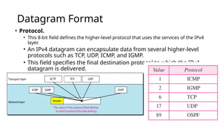
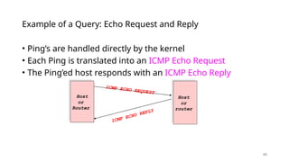
IPV4 Datagram
structure, ICMP,
DHCP and NAT
Nalinadevi Kadiresan
Lecture 9: 2-8-05 2
Internet Protocol --- Important
Concepts
• IP forwarding  global addressing, alternatives, lookup
tables
• IP addressing  hierarchical, CIDR, (taught last class and
worksheet supplied)
• IP service  best effort, simplicity of routers
• IP packets  header fields, fragmentation, ICMP
IP Service Model
• Low-level communication model
provided by Internet
• Datagram
• Each packet self-contained
• All information needed to
get to destination
• No advance setup or
connection maintenance
• Analogous to letter or telegram
3
Datagram Format
 Header length (HLEN).
 This 4-bit field defines the total length of the datagram header in 4-byte words.
 This field is needed because the header’s length is variable (between 20 and 60
bytes).
 Services.
 IETF has changed the interpretation and name of this 8-bit field.
 This field, previously called service type, is now called differentiated services.
Service Type
 In this interpretation, the first 3 bits are called precedence bits.
 The next 4 bits are called type of service (TOS) bits, and the last bit is not used.
 Precedence is a 3-bit subfield ranging from 0 (000 in binary) to 7 (111 in binary).
 The precedence defines the priority of the datagram in issues such as congestion.
 If a router is congested and needs to discard some datagrams, those
datagrams with lowest precedence are discarded first.
Service type or differentiated services
 In differentiated services, according to Table,
When the 3 rightmost bits are not all 0’s, the 6
bits define 64 services based on the priority
assignment by the Internet or local authorities.
 TOS bits is a 4-bit subfield with each bit
having a special meaning.
 Although a bit can be either 0 or 1, one
and only one of the bits can have the value
of 1 in each datagram.
Default TOS Values for
codepoints
Datagram Format
• Total length. This is a 16-bit field that defines the total length (header plus data) of
the IPv4 datagram in bytes.
• To find the length of the data coming from the upper layer, subtract the header length
from the total length.
• The total length field defines the total length of the datagram including the header.
• The header length can be found by multiplying the value in the HLEN field by 4.
• Length of data =total length - header length
• Since the field length is 16 bits, the total length of the IPv4 datagram is limited to
65,535 (2^16 - 1) bytes, of which 20 to 60 bytes are the header and the rest is data
from the upper layer.
Encapsulation of a small datagram in
an Ethernet frame
Datagram Format
 Identification. This field is used in fragmentation.
 Flags. This field is used in fragmentation.
 Fragmentation offset. This field is used in fragmentation.
 Time to live. A datagram has a limited lifetime in its travel through
the internet.
 This field was originally designed to hold a timestamp, where each visited
router decreases the value. The datagram was discarded when the value
became zero.
Datagram Format
• Protocol.
• This 8-bit field defines the higher-level protocol that uses the services of the IPv4
layer.
• An IPv4 datagram can encapsulate data from several higher-level
protocols such as TCP, UDP, ICMP, and IGMP.
• This field specifies the final destination protocol to which the IPv4
datagram is delivered.
Datagram Format
 Checksum.
 Source address. This 32-bit field defines the IPv4 address of the
source. This field must remain unchanged during the time the IPv4
datagram travels from the source host to the destination host.
 Destination address. This 32-bit field defines the IPv4 address of
the destination. This field must remain unchanged during the time
the IPv4 datagram travels from the source host to the destination
host
20.12
An IPv4 packet has arrived with the first 8 bits as shown:
01000010
The receiver discards the packet. Why?
Solution
There is an error in this packet. The 4 leftmost bits (0100)
show the version, which is correct. The next 4 bits (0010)
show an invalid header length (2 × 4 = 8). The minimum
number of bytes in the header must be 20. The packet has
been corrupted in transmission.
Example
20.13
In an IPv4 packet, the value of HLEN is 1000 in binary.
How many bytes of options are being carried by this
packet?
Solution
The HLEN value is 8, which means the total number of
bytes in the header is 8 × 4, or 32 bytes. The first 20 bytes
are the base header, the next 12 bytes are the options.
Example
Fragmentation
• Data field of a large IP packet is fragmented.
• The fragments are sent into a series of smaller IP packets
fitting a network’s MTU.
• Fragmentation is done by routers
• Fragmentation may be done multiple times along the route.
Fragmentation
• If IP packet is longer than the MTU, the router breaks packet
into smaller packets.
• Called IP fragments.
• Fragments are still IP packets.
Fragmentation
 Maximum Transfer Unit (MTU)
 Each data link layer protocol has its own frame format in most
protocols.
 One of the fields defined in the format is the maximum size of
the data field.
 In other words, when a datagram is encapsulated in a frame, the
total size of the datagram must be less than this maximum size.
Fragmentation
 A maximum transmission unit (MTU) is the largest size packet
or frame, specified in octets (eight-bit bytes), that can be sent
in a packet- or frame-based network such as the Internet.
 In a case where a router receives a protocol data unit (PDU) larger than
the next hop's MTU.
 It has two options if the transport is IPv4: drop the PDU and send an
ICMP message which indicates the condition Packet too Big, or
fragment the IP packet and send it over the link with a smaller MTU.
Fragmentation
• The value of the MTU depends on the physical network protocol.
MTUs for some networks
Fields Related to Fragmentation
 Identification. This 16-bit field identifies a datagram originating from
the source host.
 The combination of the identification and source IPv4 address must
uniquely define a datagram as it leaves the source host.
 To guarantee uniqueness, the IPv4 protocol uses a counter to label the
datagrams.
 All fragments have the same identification number, the same as the
original datagram.
Fields Related to Fragmentation
• Flags. This is a 3-bit field. The first bit is reserved.
• The second bit is called the do not fragment bit.
• If its value is 1, the machine must not fragment the datagram.
• If it cannot pass the datagram through any available physical network,
it discards the datagram and sends an ICMP error message to the
source host
Flags
Fields Related to Fragmentation
• If its value is 0, the datagram can be fragmented if necessary.
• The third bit is called the more fragment bit. If its value is 1, it means
the datagram is not the last fragment; there are more fragments after
this one.
• Fragmentation offset. This 13-bit field shows the relative position of
this fragment with respect to the whole datagram.
Fields Related to Fragmentation
• It is the offset of the data in the original datagram measured in units
of 8 bytes.
• The bytes in the original datagram are numbered 0 to 3999. The first
fragment carries bytes 0 to 1399.
• The offset for this datagram is 0/8 =0
• The second fragment carries bytes 1400 to 2799; the offset value for
this fragment is 1400/8 = 175.
Fields Related to Fragmentation
• Finally, the third fragment carries bytes 2800 to 3999. The offset value
for this fragment is 2800/8 =350.
• Notice the value of the identification field is the same in all fragments.
Fragmentation example
Detailed Fragmentation example
20.27
A packet has arrived with an M bit value of 0. Is this the
first fragment, the last fragment, or a middle fragment? Do
we know if the packet was fragmented?
Solution :
If the M bit is 0, it means that there are no more
fragments; the fragment is the last one. However, we
cannot say if the original packet was fragmented or not. A
non-fragmented packet is considered the last fragment.
Example
20.28
A packet has arrived with an M bit value of 1. Is this the
first fragment, the last fragment, or a middle fragment? Do
we know if the packet was fragmented?
Solution
If the M bit is 1, it means that there is at least one more
fragment. This fragment can be the first one or a middle
one, but not the last one. We don’t know if it is the first
one or a middle one; we need more information (the value
of the fragmentation offset).
Example
20.29
A packet has arrived with an M bit value of 1 and a
fragmentation offset value of 0. Is this the first fragment,
the last fragment, or a middle fragment?
Solution
Because the M bit is 1, it is either the first fragment or a
middle one. Because the offset value is 0, it is the first
fragment.
Example
20.30
A packet has arrived in which the offset value is 100. What
is the number of the first byte? Do we know the number of
the last byte?
Solution
To find the number of the first byte, we multiply the offset
value by 8. This means that the first byte number is 800.
We cannot determine the number of the last byte unless
we know the length.
Example
20.31
A packet has arrived in which the offset value is 100, the
value of HLEN is 5, and the value of the total length field is
100. What are the numbers of the first byte and the last
byte?
Solution
The first byte number is 100 × 8 = 800. The total length is
100 bytes, and the header length is 20 bytes (5 × 4), which
means that there are 80 bytes in this datagram. If the first
byte number is 800, the last byte number must be 879.
Example
Checksum
 The checksum in the IPv4 packet covers only the header, not the
data.
 The implementation of the checksum in the IPv4 packet follows the
same principles.
 First, the value of the checksum field is set to 0. Then the entire
header is divided into 16-bit sections and added together. The result
(sum) is complemented and inserted into the checksum field.
Options
• Options, as the name implies, are not required for a datagram.
• They can be used for network testing and debugging.
• Although options are not a required part of the IPv4 header, option
processing is required of the IPv4 software.
Options
Options
• An end-of-option option is a 1-byte option used for padding at the end of the option
field.
• A record route option is used to record the Internet routers that handle the
datagram. It can list up to nine router addresses.
• A strict source route option is used by the source to predetermine a route for the
datagram as it travels through the Internet.
• A loose source route option is similar to the strict source route, but it is less rigid.
• A timestamp option is used to record the time of datagram processing by a router
Lecture 9: 2-8-05 36
Fragmentation is Harmful
• Uses resources poorly
• Forwarding costs per packet
• Best if we can send large chunks of data
• Worst case: packet just bigger than MTU
• Poor end-to-end performance
• Loss of a fragment
• Path MTU discovery protocol  determines minimum MTU along route
• Uses ICMP error messages
• Common theme in system design
• Assure correctness by implementing complete protocol
• Optimize common cases to avoid full complexity
Internet Control Message Protocol
(ICMP)
• Short messages used to send error & other control information
• Examples
• Ping request / response
• Can use to check whether remote host reachable
• Destination unreachable
• Indicates how packet got & why couldn’t go further
• Flow control
• Slow down packet delivery rate
• Redirect
• Suggest alternate routing path for future messages
• Router solicitation / advertisement
• Helps newly connected host discover local router
• Timeout
• Packet exceeded maximum hop limit
38
• The IP (Internet Protocol) relies on several other protocols to
perform necessary control and routing functions:
• Control functions (ICMP)
• Multicast signaling (IGMP)
• Setting up routing tables (RIP, OSPF, BGP, PIM, …)
Control
Routing
ICMP IGMP
RIP OSPF BGP PIM
Overview
39
Overview
• The Internet Control Message Protocol (ICMP)
is a helper protocol that supports IP with facility
for
• Error reporting
• Simple queries
• ICMP messages are encapsulated as IP
datagrams:
IP header ICMP message
IP payload
40
ICMP message format
additional information
or
0x00000000
type code checksum
bit # 0 15 23 24
8 31
7 16
4 byte header:
• Type (1 byte): type of ICMP message
• Code (1 byte): subtype of ICMP message
• Checksum (2 bytes): similar to IP header checksum.
Checksum is calculated over entire ICMP message
If there is no additional data, there are 4 bytes set to zero.
 each ICMP messages is at least 8 bytes long
42
ICMP Query message
ICMP query:
• Request sent by host to a router or host
• Reply sent back to querying host
Host
ICMP Request
Host or router
ICMP Reply
43
Example of ICMP Queries
Type/Code: Description
8/0 Echo Request
0/0 Echo Reply
13/0 Timestamp Request
14/0 Timestamp Reply
10/0 Router Solicitation
9/0 Router Advertisement
The ping command
uses Echo Request/
Echo Reply
44
• Ping’s are handled directly by the kernel
• Each Ping is translated into an ICMP Echo Request
• The Ping’ed host responds with an ICMP Echo Reply
Example of a Query: Echo Request and Reply
Host
or
Router
ICMP ECHO REQUEST
Host
or
router
ICMP ECHO REPLY
45
Example of a Query: ICMP Timestamp
• A system (host or router) asks
another system for the current
time.
• Time is measured in
milliseconds after midnight
UTC (Universal Coordinated
Time) of the current day
• Sender sends a request,
receiver responds with reply
Type
(= 17or18)
Code
(=0)
Checksum
32-bitsendertimestamp
identifier sequencenumber
32-bitreceivetimestamp
32-bittransmittimestamp
Sender
Receiver
Timestamp
Request
Timestamp
Reply
46
ICMP Error message
• ICMP error messages report error conditions
• Typically sent when a datagram is discarded
• Error message is often passed from ICMP to the
application program
Host
IP datagram
Host or router
ICMP Error
Message
IP datagram
is discarded
47
ICMP Error message
• ICMP error messages include the complete IP header and the first 8 bytes of
the payload (typically: UDP, TCP)
Unused (0x00000000)
IP header ICMP header IP header 8 bytes of payload
ICMP Message
from IP datagram that triggered the error
type code checksum
48
IP MTU Discovery with ICMP
• Typically send series of packets from one host to another
• Typically, all will follow same route
• Routes remain stable for minutes at a time
• Makes sense to determine path MTU before sending real packets
• Operation
• Send max-sized packet with “do not fragment” flag set
• If encounters problem, ICMP message will be returned
• “Destination unreachable: Fragmentation needed”
• Usually indicates MTU encountered
host
host
router
router
MTU = 4000
MTU = 1500
MTU =
2000
Lecture 9: 2-8-05 49
IP MTU Discovery with ICMP
MTU = 4000
host
host
router
MTU = 1500
MTU =
2000
IP
Packet
Length = 4000, Don’t Fragment
router
ICMP
Frag. Needed
MTU = 2000
Lecture 9: 2-8-05 50
IP MTU Discovery with ICMP
MTU = 4000
host
host
MTU = 1500
MTU =
2000
IP
Packet
Length = 2000, Don’t Fragment
router
ICMP
Frag. Needed
MTU = 1500
router
Lecture 9: 2-8-05 51
IP MTU Discovery with ICMP
• When successful, no reply at the IP level
• “No news is good news”
• Higher level protocol might have some form of
acknowledgment
MTU = 4000
host
host
MTU = 1500
MTU =
2000
IP
Packet
Length = 1500, Don’t Fragment
router
router
52
Example: ICMP Port Unreachable
• RFC 792: If, in the destination host, the IP module cannot deliver the
datagram because the indicated protocol module or process port is not active,
the destination host may send a destination unreachable message to the
source host.
• Scenario:
Client
Request a service
at a port 80
Server
No process
is waiting
at port 80
Port
Unreachable
IP addresses: how to get one?
That’s actually two questions:
1. Q: How does a host get IP address within its network (host part of
address)?
2. Q: How does a network get IP address for itself (network part of
address)
How does host get IP address?
 hard-coded by sysadmin in config file (e.g., /etc/rc.config in UNIX)
 DHCP: Dynamic Host Configuration Protocol: dynamically get address
from as server
• “plug-and-play”
Network Layer: 4-53
DHCP: Dynamic Host Configuration
Protocol
goal: host dynamically obtains IP address from network server when it
“joins” network
 can renew its lease on address in use
 allows reuse of addresses (only hold address while connected/on)
 support for mobile users who join/leave network
DHCP overview:
 host broadcasts DHCP discover msg [optional]
 DHCP server responds with DHCP offer msg [optional]
 host requests IP address: DHCP request msg
 DHCP server sends address: DHCP ack msg
Network Layer: 4-54
DHCP client-server scenario
223.1.1.1
223.1.1.2
223.1.1.3
223.1.1.4 223.1.2.9
223.1.2.2
223.1.2.1
223.1.3.2
223.1.3.1
223.1.3.27
DHCP server
223.1.2.5
arriving DHCP client needs
address in this network
Typically, DHCP server will be co-
located in router, serving all subnets
to which router is attached
Network Layer: 4-55
DHCP client-server scenario
DHCP server: 223.1.2.5
Arriving client
DHCP discover
src : 0.0.0.0, 68
dest.: 255.255.255.255,67
yiaddr: 0.0.0.0
transaction ID: 654
DHCP offer
src: 223.1.2.5, 67
dest: 255.255.255.255, 68
yiaddr: 223.1.2.4
transaction ID: 654
lifetime: 3600 secs
DHCP request
src: 0.0.0.0, 68
dest:: 255.255.255.255, 67
yiaddr: 223.1.2.4
transaction ID: 655
lifetime: 3600 secs
DHCP ACK
src: 223.1.2.5, 67
dest: 255.255.255.255, 68
yiaddr: 223.1.2.4
transaction ID: 655
lifetime: 3600 secs
Broadcast: is there a
DHCP server out there?
Broadcast: I’m a DHCP
server! Here’s an IP
address you can use
Broadcast: OK. I would
like to use this IP
address!
Broadcast: OK. You’ve
got that IP address!
The two steps above can
be skipped “if a client
remembers and wishes to
reuse a previously
allocated network address”
[RFC 2131]
Network Layer: 4-56
DHCP: more than IP addresses
DHCP can return more than just allocated IP address on
subnet:
 address of first-hop router for client
 name and IP address of DNS sever
 network mask (indicating network versus host portion of address)
Network Layer: 4-57
DHCP: example
 Connecting laptop will use DHCP
to get IP address, address of first-
hop router, address of DNS server.
router with DHCP
server built into
router
 DHCP REQUEST message encapsulated
in UDP, encapsulated in IP, encapsulated
in Ethernet
 Ethernet frame broadcast (dest:
FFFFFFFFFFFF) on LAN, received at router
running DHCP server
 Ethernet de-mux’ed to IP de-mux’ed,
UDP de-mux’ed to DHCP
168.1.1.1
DHCP
UDP
IP
Eth
Phy
DHCP
DHCP
DHCP
DHCP
DHCP
DHCP
UDP
IP
Eth
Phy
DHCP
DHCP
DHCP
DHCP
DHCP
Network Layer: 4-58
DHCP: example
 DHCP server formulates DHCP ACK
containing client’s IP address, IP
address of first-hop router for client,
name & IP address of DNS server
 encapsulated DHCP server reply
forwarded to client, de-muxing up to
DHCP at client
router with DHCP
server built into
router
DHCP
DHCP
DHCP
DHCP
DHCP
UDP
IP
Eth
Phy
DHCP
DHCP
UDP
IP
Eth
Phy
DHCP
DHCP
DHCP
DHCP
 client now knows its IP address, name
and IP address of DNS server, IP
address of its first-hop router
Network Layer: 4-59
IP addresses: how to get one?
Q: how does network get subnet part of IP address?
A: gets allocated portion of its provider ISP’s address space
ISP's block 11001000 00010111 00010000 00000000 200.23.16.0/20
ISP can then allocate out its address space in 8 blocks:
Organization 0 11001000 00010111 00010000 00000000 200.23.16.0/23
Organization 1 11001000 00010111 00010010 00000000 200.23.18.0/23
Organization 2 11001000 00010111 00010100 00000000 200.23.20.0/23
... ….. …. ….
Organization 7 11001000 00010111 00011110 00000000 200.23.30.0/23
Network Layer: 4-60
Hierarchical addressing: route aggregation
“Send me anything
with addresses
beginning
200.23.16.0/20”
200.23.16.0/23
200.23.18.0/23
200.23.30.0/23
Fly-By-Night-ISP
Organization 0
Organization 7
Internet
Organization 1
ISPs-R-Us
“Send me anything
with addresses
beginning
199.31.0.0/16”
200.23.20.0/23
Organization 2
.
.
.
.
.
.
hierarchical addressing allows efficient advertisement of
routing information:
Network Layer: 4-61
Hierarchical addressing: more specific routes
“Send me anything
with addresses
beginning
200.23.16.0/20”
200.23.16.0/23
200.23.30.0/23
Fly-By-Night-ISP
Organization 0
Organization 7
Internet
200.23.18.0/23
Organization 1
ISPs-R-Us
“Send me anything
with addresses
beginning
199.31.0.0/16”
200.23.20.0/23
Organization 2
.
.
.
.
.
.
 Organization 1 moves from Fly-By-Night-ISP to ISPs-R-Us
 ISPs-R-Us now advertises a more specific route to Organization 1
200.23.18.0/23
Organization 1
“or 200.23.18.0/23”
Network Layer: 4-62
Hierarchical addressing: more specific routes
“Send me anything
with addresses
beginning
200.23.16.0/20”
200.23.16.0/23
200.23.30.0/23
Fly-By-Night-ISP
Organization 0
Organization 7
Internet
ISPs-R-Us
“Send me anything
with addresses
beginning
199.31.0.0/16”
200.23.20.0/23
Organization 2
.
.
.
.
.
.
 Organization 1 moves from Fly-By-Night-ISP to ISPs-R-Us
 ISPs-R-Us now advertises a more specific route to Organization 1
200.23.18.0/23
Organization 1
“or 200.23.18.0/23”
Network Layer: 4-63
IP addressing: last words ...
Q: how does an ISP get block of
addresses?
A: ICANN: Internet Corporation for
Assigned Names and Numbers
http://www.icann.org/
• allocates IP addresses, through 5
regional registries (RRs) (who may
then allocate to local registries)
• manages DNS root zone, including
delegation of individual TLD (.com,
.edu , …) management
Q: are there enough 32-bit IP
addresses?
 ICANN allocated last chunk of
IPv4 addresses to RRs in 2011
 NAT (next) helps IPv4 address
space exhaustion
 IPv6 has 128-bit address space
"Who the hell knew how much address
space we needed?" Vint Cerf (reflecting
on decision to make IPv4 address 32 bits
long)
Network Layer: 4-64
10.0.0.1
10.0.0.2
10.0.0.3
10.0.0.4
local network (e.g., home
network) 10.0.0/24
138.76.29.7
rest of
Internet
NAT: network address translation
datagrams with source or destination in
this network have 10.0.0/24 address for
source, destination (as usual)
all datagrams leaving local network have
same source NAT IP address: 138.76.29.7,
but different source port numbers
NAT: all devices in local network share just one IPv4 address as
far as outside world is concerned
Network Layer: 4-65
 all devices in local network have 32-bit addresses in a “private” IP
address space (10/8, 172.16/12, 192.168/16 prefixes) that can only
be used in local network
 advantages:
 just one IP address needed from provider ISP for all devices
 can change addresses of host in local network without notifying
outside world
 can change ISP without changing addresses of devices in local
network
 security: devices inside local net not directly addressable, visible
by outside world
NAT: network address translation
Network Layer: 4-66
implementation: NAT router must (transparently):
 outgoing datagrams: replace (source IP address, port #) of every
outgoing datagram to (NAT IP address, new port #)
• remote clients/servers will respond using (NAT IP address, new port
#) as destination address
 remember (in NAT translation table) every (source IP address, port #)
to (NAT IP address, new port #) translation pair
 incoming datagrams: replace (NAT IP address, new port #) in
destination fields of every incoming datagram with corresponding
(source IP address, port #) stored in NAT table
NAT: network address translation
Network Layer: 4-67
NAT: network address translation
S: 10.0.0.1, 3345
D: 128.119.40.186, 80
1
10.0.0.4
138.76.29.7
1: host 10.0.0.1 sends
datagram to
128.119.40.186, 80
NAT translation table
WAN side addr LAN side addr
138.76.29.7, 5001 10.0.0.1, 3345
…… ……
S: 128.119.40.186, 80
D: 10.0.0.1, 3345
4
S: 138.76.29.7, 5001
D: 128.119.40.186, 80
2
2: NAT router changes
datagram source address
from 10.0.0.1, 3345 to
138.76.29.7, 5001,
updates table
S: 128.119.40.186, 80
D: 138.76.29.7, 5001 3
3: reply arrives, destination
address: 138.76.29.7, 5001
10.0.0.1
10.0.0.2
10.0.0.3
Network Layer: 4-68
 NAT has been controversial:
• routers “should” only process up to layer 3
• address “shortage” should be solved by IPv6
• violates end-to-end argument (port # manipulation by network-layer device)
• NAT traversal: what if client wants to connect to server behind NAT?
 but NAT is here to stay:
• extensively used in home and institutional nets, 4G/5G cellular nets
NAT: network address translation
Network Layer: 4-69

IP datagram structure, ICMP,DHCP, NAT Introduction

  • 1.
    IPV4 Datagram structure, ICMP, DHCPand NAT Nalinadevi Kadiresan
  • 2.
    Lecture 9: 2-8-052 Internet Protocol --- Important Concepts • IP forwarding  global addressing, alternatives, lookup tables • IP addressing  hierarchical, CIDR, (taught last class and worksheet supplied) • IP service  best effort, simplicity of routers • IP packets  header fields, fragmentation, ICMP
  • 3.
    IP Service Model •Low-level communication model provided by Internet • Datagram • Each packet self-contained • All information needed to get to destination • No advance setup or connection maintenance • Analogous to letter or telegram 3
  • 4.
    Datagram Format  Headerlength (HLEN).  This 4-bit field defines the total length of the datagram header in 4-byte words.  This field is needed because the header’s length is variable (between 20 and 60 bytes).  Services.  IETF has changed the interpretation and name of this 8-bit field.  This field, previously called service type, is now called differentiated services. Service Type  In this interpretation, the first 3 bits are called precedence bits.  The next 4 bits are called type of service (TOS) bits, and the last bit is not used.  Precedence is a 3-bit subfield ranging from 0 (000 in binary) to 7 (111 in binary).  The precedence defines the priority of the datagram in issues such as congestion.  If a router is congested and needs to discard some datagrams, those datagrams with lowest precedence are discarded first.
  • 5.
    Service type ordifferentiated services  In differentiated services, according to Table, When the 3 rightmost bits are not all 0’s, the 6 bits define 64 services based on the priority assignment by the Internet or local authorities.  TOS bits is a 4-bit subfield with each bit having a special meaning.  Although a bit can be either 0 or 1, one and only one of the bits can have the value of 1 in each datagram.
  • 6.
    Default TOS Valuesfor codepoints
  • 7.
    Datagram Format • Totallength. This is a 16-bit field that defines the total length (header plus data) of the IPv4 datagram in bytes. • To find the length of the data coming from the upper layer, subtract the header length from the total length. • The total length field defines the total length of the datagram including the header. • The header length can be found by multiplying the value in the HLEN field by 4. • Length of data =total length - header length • Since the field length is 16 bits, the total length of the IPv4 datagram is limited to 65,535 (2^16 - 1) bytes, of which 20 to 60 bytes are the header and the rest is data from the upper layer.
  • 8.
    Encapsulation of asmall datagram in an Ethernet frame
  • 9.
    Datagram Format  Identification.This field is used in fragmentation.  Flags. This field is used in fragmentation.  Fragmentation offset. This field is used in fragmentation.  Time to live. A datagram has a limited lifetime in its travel through the internet.  This field was originally designed to hold a timestamp, where each visited router decreases the value. The datagram was discarded when the value became zero.
  • 10.
    Datagram Format • Protocol. •This 8-bit field defines the higher-level protocol that uses the services of the IPv4 layer. • An IPv4 datagram can encapsulate data from several higher-level protocols such as TCP, UDP, ICMP, and IGMP. • This field specifies the final destination protocol to which the IPv4 datagram is delivered.
  • 11.
    Datagram Format  Checksum. Source address. This 32-bit field defines the IPv4 address of the source. This field must remain unchanged during the time the IPv4 datagram travels from the source host to the destination host.  Destination address. This 32-bit field defines the IPv4 address of the destination. This field must remain unchanged during the time the IPv4 datagram travels from the source host to the destination host
  • 12.
    20.12 An IPv4 packethas arrived with the first 8 bits as shown: 01000010 The receiver discards the packet. Why? Solution There is an error in this packet. The 4 leftmost bits (0100) show the version, which is correct. The next 4 bits (0010) show an invalid header length (2 × 4 = 8). The minimum number of bytes in the header must be 20. The packet has been corrupted in transmission. Example
  • 13.
    20.13 In an IPv4packet, the value of HLEN is 1000 in binary. How many bytes of options are being carried by this packet? Solution The HLEN value is 8, which means the total number of bytes in the header is 8 × 4, or 32 bytes. The first 20 bytes are the base header, the next 12 bytes are the options. Example
  • 14.
    Fragmentation • Data fieldof a large IP packet is fragmented. • The fragments are sent into a series of smaller IP packets fitting a network’s MTU. • Fragmentation is done by routers • Fragmentation may be done multiple times along the route.
  • 15.
    Fragmentation • If IPpacket is longer than the MTU, the router breaks packet into smaller packets. • Called IP fragments. • Fragments are still IP packets.
  • 16.
    Fragmentation  Maximum TransferUnit (MTU)  Each data link layer protocol has its own frame format in most protocols.  One of the fields defined in the format is the maximum size of the data field.  In other words, when a datagram is encapsulated in a frame, the total size of the datagram must be less than this maximum size.
  • 17.
    Fragmentation  A maximumtransmission unit (MTU) is the largest size packet or frame, specified in octets (eight-bit bytes), that can be sent in a packet- or frame-based network such as the Internet.  In a case where a router receives a protocol data unit (PDU) larger than the next hop's MTU.  It has two options if the transport is IPv4: drop the PDU and send an ICMP message which indicates the condition Packet too Big, or fragment the IP packet and send it over the link with a smaller MTU.
  • 18.
    Fragmentation • The valueof the MTU depends on the physical network protocol.
  • 19.
    MTUs for somenetworks
  • 20.
    Fields Related toFragmentation  Identification. This 16-bit field identifies a datagram originating from the source host.  The combination of the identification and source IPv4 address must uniquely define a datagram as it leaves the source host.  To guarantee uniqueness, the IPv4 protocol uses a counter to label the datagrams.  All fragments have the same identification number, the same as the original datagram.
  • 21.
    Fields Related toFragmentation • Flags. This is a 3-bit field. The first bit is reserved. • The second bit is called the do not fragment bit. • If its value is 1, the machine must not fragment the datagram. • If it cannot pass the datagram through any available physical network, it discards the datagram and sends an ICMP error message to the source host Flags
  • 22.
    Fields Related toFragmentation • If its value is 0, the datagram can be fragmented if necessary. • The third bit is called the more fragment bit. If its value is 1, it means the datagram is not the last fragment; there are more fragments after this one. • Fragmentation offset. This 13-bit field shows the relative position of this fragment with respect to the whole datagram.
  • 23.
    Fields Related toFragmentation • It is the offset of the data in the original datagram measured in units of 8 bytes. • The bytes in the original datagram are numbered 0 to 3999. The first fragment carries bytes 0 to 1399. • The offset for this datagram is 0/8 =0 • The second fragment carries bytes 1400 to 2799; the offset value for this fragment is 1400/8 = 175.
  • 24.
    Fields Related toFragmentation • Finally, the third fragment carries bytes 2800 to 3999. The offset value for this fragment is 2800/8 =350. • Notice the value of the identification field is the same in all fragments.
  • 25.
  • 26.
  • 27.
    20.27 A packet hasarrived with an M bit value of 0. Is this the first fragment, the last fragment, or a middle fragment? Do we know if the packet was fragmented? Solution : If the M bit is 0, it means that there are no more fragments; the fragment is the last one. However, we cannot say if the original packet was fragmented or not. A non-fragmented packet is considered the last fragment. Example
  • 28.
    20.28 A packet hasarrived with an M bit value of 1. Is this the first fragment, the last fragment, or a middle fragment? Do we know if the packet was fragmented? Solution If the M bit is 1, it means that there is at least one more fragment. This fragment can be the first one or a middle one, but not the last one. We don’t know if it is the first one or a middle one; we need more information (the value of the fragmentation offset). Example
  • 29.
    20.29 A packet hasarrived with an M bit value of 1 and a fragmentation offset value of 0. Is this the first fragment, the last fragment, or a middle fragment? Solution Because the M bit is 1, it is either the first fragment or a middle one. Because the offset value is 0, it is the first fragment. Example
  • 30.
    20.30 A packet hasarrived in which the offset value is 100. What is the number of the first byte? Do we know the number of the last byte? Solution To find the number of the first byte, we multiply the offset value by 8. This means that the first byte number is 800. We cannot determine the number of the last byte unless we know the length. Example
  • 31.
    20.31 A packet hasarrived in which the offset value is 100, the value of HLEN is 5, and the value of the total length field is 100. What are the numbers of the first byte and the last byte? Solution The first byte number is 100 × 8 = 800. The total length is 100 bytes, and the header length is 20 bytes (5 × 4), which means that there are 80 bytes in this datagram. If the first byte number is 800, the last byte number must be 879. Example
  • 32.
    Checksum  The checksumin the IPv4 packet covers only the header, not the data.  The implementation of the checksum in the IPv4 packet follows the same principles.  First, the value of the checksum field is set to 0. Then the entire header is divided into 16-bit sections and added together. The result (sum) is complemented and inserted into the checksum field.
  • 33.
    Options • Options, asthe name implies, are not required for a datagram. • They can be used for network testing and debugging. • Although options are not a required part of the IPv4 header, option processing is required of the IPv4 software.
  • 34.
  • 35.
    Options • An end-of-optionoption is a 1-byte option used for padding at the end of the option field. • A record route option is used to record the Internet routers that handle the datagram. It can list up to nine router addresses. • A strict source route option is used by the source to predetermine a route for the datagram as it travels through the Internet. • A loose source route option is similar to the strict source route, but it is less rigid. • A timestamp option is used to record the time of datagram processing by a router
  • 36.
    Lecture 9: 2-8-0536 Fragmentation is Harmful • Uses resources poorly • Forwarding costs per packet • Best if we can send large chunks of data • Worst case: packet just bigger than MTU • Poor end-to-end performance • Loss of a fragment • Path MTU discovery protocol  determines minimum MTU along route • Uses ICMP error messages • Common theme in system design • Assure correctness by implementing complete protocol • Optimize common cases to avoid full complexity
  • 37.
    Internet Control MessageProtocol (ICMP) • Short messages used to send error & other control information • Examples • Ping request / response • Can use to check whether remote host reachable • Destination unreachable • Indicates how packet got & why couldn’t go further • Flow control • Slow down packet delivery rate • Redirect • Suggest alternate routing path for future messages • Router solicitation / advertisement • Helps newly connected host discover local router • Timeout • Packet exceeded maximum hop limit
  • 38.
    38 • The IP(Internet Protocol) relies on several other protocols to perform necessary control and routing functions: • Control functions (ICMP) • Multicast signaling (IGMP) • Setting up routing tables (RIP, OSPF, BGP, PIM, …) Control Routing ICMP IGMP RIP OSPF BGP PIM Overview
  • 39.
    39 Overview • The InternetControl Message Protocol (ICMP) is a helper protocol that supports IP with facility for • Error reporting • Simple queries • ICMP messages are encapsulated as IP datagrams: IP header ICMP message IP payload
  • 40.
    40 ICMP message format additionalinformation or 0x00000000 type code checksum bit # 0 15 23 24 8 31 7 16 4 byte header: • Type (1 byte): type of ICMP message • Code (1 byte): subtype of ICMP message • Checksum (2 bytes): similar to IP header checksum. Checksum is calculated over entire ICMP message If there is no additional data, there are 4 bytes set to zero.  each ICMP messages is at least 8 bytes long
  • 41.
    42 ICMP Query message ICMPquery: • Request sent by host to a router or host • Reply sent back to querying host Host ICMP Request Host or router ICMP Reply
  • 42.
    43 Example of ICMPQueries Type/Code: Description 8/0 Echo Request 0/0 Echo Reply 13/0 Timestamp Request 14/0 Timestamp Reply 10/0 Router Solicitation 9/0 Router Advertisement The ping command uses Echo Request/ Echo Reply
  • 43.
    44 • Ping’s arehandled directly by the kernel • Each Ping is translated into an ICMP Echo Request • The Ping’ed host responds with an ICMP Echo Reply Example of a Query: Echo Request and Reply Host or Router ICMP ECHO REQUEST Host or router ICMP ECHO REPLY
  • 44.
    45 Example of aQuery: ICMP Timestamp • A system (host or router) asks another system for the current time. • Time is measured in milliseconds after midnight UTC (Universal Coordinated Time) of the current day • Sender sends a request, receiver responds with reply Type (= 17or18) Code (=0) Checksum 32-bitsendertimestamp identifier sequencenumber 32-bitreceivetimestamp 32-bittransmittimestamp Sender Receiver Timestamp Request Timestamp Reply
  • 45.
    46 ICMP Error message •ICMP error messages report error conditions • Typically sent when a datagram is discarded • Error message is often passed from ICMP to the application program Host IP datagram Host or router ICMP Error Message IP datagram is discarded
  • 46.
    47 ICMP Error message •ICMP error messages include the complete IP header and the first 8 bytes of the payload (typically: UDP, TCP) Unused (0x00000000) IP header ICMP header IP header 8 bytes of payload ICMP Message from IP datagram that triggered the error type code checksum
  • 47.
    48 IP MTU Discoverywith ICMP • Typically send series of packets from one host to another • Typically, all will follow same route • Routes remain stable for minutes at a time • Makes sense to determine path MTU before sending real packets • Operation • Send max-sized packet with “do not fragment” flag set • If encounters problem, ICMP message will be returned • “Destination unreachable: Fragmentation needed” • Usually indicates MTU encountered host host router router MTU = 4000 MTU = 1500 MTU = 2000
  • 48.
    Lecture 9: 2-8-0549 IP MTU Discovery with ICMP MTU = 4000 host host router MTU = 1500 MTU = 2000 IP Packet Length = 4000, Don’t Fragment router ICMP Frag. Needed MTU = 2000
  • 49.
    Lecture 9: 2-8-0550 IP MTU Discovery with ICMP MTU = 4000 host host MTU = 1500 MTU = 2000 IP Packet Length = 2000, Don’t Fragment router ICMP Frag. Needed MTU = 1500 router
  • 50.
    Lecture 9: 2-8-0551 IP MTU Discovery with ICMP • When successful, no reply at the IP level • “No news is good news” • Higher level protocol might have some form of acknowledgment MTU = 4000 host host MTU = 1500 MTU = 2000 IP Packet Length = 1500, Don’t Fragment router router
  • 51.
    52 Example: ICMP PortUnreachable • RFC 792: If, in the destination host, the IP module cannot deliver the datagram because the indicated protocol module or process port is not active, the destination host may send a destination unreachable message to the source host. • Scenario: Client Request a service at a port 80 Server No process is waiting at port 80 Port Unreachable
  • 52.
    IP addresses: howto get one? That’s actually two questions: 1. Q: How does a host get IP address within its network (host part of address)? 2. Q: How does a network get IP address for itself (network part of address) How does host get IP address?  hard-coded by sysadmin in config file (e.g., /etc/rc.config in UNIX)  DHCP: Dynamic Host Configuration Protocol: dynamically get address from as server • “plug-and-play” Network Layer: 4-53
  • 53.
    DHCP: Dynamic HostConfiguration Protocol goal: host dynamically obtains IP address from network server when it “joins” network  can renew its lease on address in use  allows reuse of addresses (only hold address while connected/on)  support for mobile users who join/leave network DHCP overview:  host broadcasts DHCP discover msg [optional]  DHCP server responds with DHCP offer msg [optional]  host requests IP address: DHCP request msg  DHCP server sends address: DHCP ack msg Network Layer: 4-54
  • 54.
    DHCP client-server scenario 223.1.1.1 223.1.1.2 223.1.1.3 223.1.1.4223.1.2.9 223.1.2.2 223.1.2.1 223.1.3.2 223.1.3.1 223.1.3.27 DHCP server 223.1.2.5 arriving DHCP client needs address in this network Typically, DHCP server will be co- located in router, serving all subnets to which router is attached Network Layer: 4-55
  • 55.
    DHCP client-server scenario DHCPserver: 223.1.2.5 Arriving client DHCP discover src : 0.0.0.0, 68 dest.: 255.255.255.255,67 yiaddr: 0.0.0.0 transaction ID: 654 DHCP offer src: 223.1.2.5, 67 dest: 255.255.255.255, 68 yiaddr: 223.1.2.4 transaction ID: 654 lifetime: 3600 secs DHCP request src: 0.0.0.0, 68 dest:: 255.255.255.255, 67 yiaddr: 223.1.2.4 transaction ID: 655 lifetime: 3600 secs DHCP ACK src: 223.1.2.5, 67 dest: 255.255.255.255, 68 yiaddr: 223.1.2.4 transaction ID: 655 lifetime: 3600 secs Broadcast: is there a DHCP server out there? Broadcast: I’m a DHCP server! Here’s an IP address you can use Broadcast: OK. I would like to use this IP address! Broadcast: OK. You’ve got that IP address! The two steps above can be skipped “if a client remembers and wishes to reuse a previously allocated network address” [RFC 2131] Network Layer: 4-56
  • 56.
    DHCP: more thanIP addresses DHCP can return more than just allocated IP address on subnet:  address of first-hop router for client  name and IP address of DNS sever  network mask (indicating network versus host portion of address) Network Layer: 4-57
  • 57.
    DHCP: example  Connectinglaptop will use DHCP to get IP address, address of first- hop router, address of DNS server. router with DHCP server built into router  DHCP REQUEST message encapsulated in UDP, encapsulated in IP, encapsulated in Ethernet  Ethernet frame broadcast (dest: FFFFFFFFFFFF) on LAN, received at router running DHCP server  Ethernet de-mux’ed to IP de-mux’ed, UDP de-mux’ed to DHCP 168.1.1.1 DHCP UDP IP Eth Phy DHCP DHCP DHCP DHCP DHCP DHCP UDP IP Eth Phy DHCP DHCP DHCP DHCP DHCP Network Layer: 4-58
  • 58.
    DHCP: example  DHCPserver formulates DHCP ACK containing client’s IP address, IP address of first-hop router for client, name & IP address of DNS server  encapsulated DHCP server reply forwarded to client, de-muxing up to DHCP at client router with DHCP server built into router DHCP DHCP DHCP DHCP DHCP UDP IP Eth Phy DHCP DHCP UDP IP Eth Phy DHCP DHCP DHCP DHCP  client now knows its IP address, name and IP address of DNS server, IP address of its first-hop router Network Layer: 4-59
  • 59.
    IP addresses: howto get one? Q: how does network get subnet part of IP address? A: gets allocated portion of its provider ISP’s address space ISP's block 11001000 00010111 00010000 00000000 200.23.16.0/20 ISP can then allocate out its address space in 8 blocks: Organization 0 11001000 00010111 00010000 00000000 200.23.16.0/23 Organization 1 11001000 00010111 00010010 00000000 200.23.18.0/23 Organization 2 11001000 00010111 00010100 00000000 200.23.20.0/23 ... ….. …. …. Organization 7 11001000 00010111 00011110 00000000 200.23.30.0/23 Network Layer: 4-60
  • 60.
    Hierarchical addressing: routeaggregation “Send me anything with addresses beginning 200.23.16.0/20” 200.23.16.0/23 200.23.18.0/23 200.23.30.0/23 Fly-By-Night-ISP Organization 0 Organization 7 Internet Organization 1 ISPs-R-Us “Send me anything with addresses beginning 199.31.0.0/16” 200.23.20.0/23 Organization 2 . . . . . . hierarchical addressing allows efficient advertisement of routing information: Network Layer: 4-61
  • 61.
    Hierarchical addressing: morespecific routes “Send me anything with addresses beginning 200.23.16.0/20” 200.23.16.0/23 200.23.30.0/23 Fly-By-Night-ISP Organization 0 Organization 7 Internet 200.23.18.0/23 Organization 1 ISPs-R-Us “Send me anything with addresses beginning 199.31.0.0/16” 200.23.20.0/23 Organization 2 . . . . . .  Organization 1 moves from Fly-By-Night-ISP to ISPs-R-Us  ISPs-R-Us now advertises a more specific route to Organization 1 200.23.18.0/23 Organization 1 “or 200.23.18.0/23” Network Layer: 4-62
  • 62.
    Hierarchical addressing: morespecific routes “Send me anything with addresses beginning 200.23.16.0/20” 200.23.16.0/23 200.23.30.0/23 Fly-By-Night-ISP Organization 0 Organization 7 Internet ISPs-R-Us “Send me anything with addresses beginning 199.31.0.0/16” 200.23.20.0/23 Organization 2 . . . . . .  Organization 1 moves from Fly-By-Night-ISP to ISPs-R-Us  ISPs-R-Us now advertises a more specific route to Organization 1 200.23.18.0/23 Organization 1 “or 200.23.18.0/23” Network Layer: 4-63
  • 63.
    IP addressing: lastwords ... Q: how does an ISP get block of addresses? A: ICANN: Internet Corporation for Assigned Names and Numbers http://www.icann.org/ • allocates IP addresses, through 5 regional registries (RRs) (who may then allocate to local registries) • manages DNS root zone, including delegation of individual TLD (.com, .edu , …) management Q: are there enough 32-bit IP addresses?  ICANN allocated last chunk of IPv4 addresses to RRs in 2011  NAT (next) helps IPv4 address space exhaustion  IPv6 has 128-bit address space "Who the hell knew how much address space we needed?" Vint Cerf (reflecting on decision to make IPv4 address 32 bits long) Network Layer: 4-64
  • 64.
    10.0.0.1 10.0.0.2 10.0.0.3 10.0.0.4 local network (e.g.,home network) 10.0.0/24 138.76.29.7 rest of Internet NAT: network address translation datagrams with source or destination in this network have 10.0.0/24 address for source, destination (as usual) all datagrams leaving local network have same source NAT IP address: 138.76.29.7, but different source port numbers NAT: all devices in local network share just one IPv4 address as far as outside world is concerned Network Layer: 4-65
  • 65.
     all devicesin local network have 32-bit addresses in a “private” IP address space (10/8, 172.16/12, 192.168/16 prefixes) that can only be used in local network  advantages:  just one IP address needed from provider ISP for all devices  can change addresses of host in local network without notifying outside world  can change ISP without changing addresses of devices in local network  security: devices inside local net not directly addressable, visible by outside world NAT: network address translation Network Layer: 4-66
  • 66.
    implementation: NAT routermust (transparently):  outgoing datagrams: replace (source IP address, port #) of every outgoing datagram to (NAT IP address, new port #) • remote clients/servers will respond using (NAT IP address, new port #) as destination address  remember (in NAT translation table) every (source IP address, port #) to (NAT IP address, new port #) translation pair  incoming datagrams: replace (NAT IP address, new port #) in destination fields of every incoming datagram with corresponding (source IP address, port #) stored in NAT table NAT: network address translation Network Layer: 4-67
  • 67.
    NAT: network addresstranslation S: 10.0.0.1, 3345 D: 128.119.40.186, 80 1 10.0.0.4 138.76.29.7 1: host 10.0.0.1 sends datagram to 128.119.40.186, 80 NAT translation table WAN side addr LAN side addr 138.76.29.7, 5001 10.0.0.1, 3345 …… …… S: 128.119.40.186, 80 D: 10.0.0.1, 3345 4 S: 138.76.29.7, 5001 D: 128.119.40.186, 80 2 2: NAT router changes datagram source address from 10.0.0.1, 3345 to 138.76.29.7, 5001, updates table S: 128.119.40.186, 80 D: 138.76.29.7, 5001 3 3: reply arrives, destination address: 138.76.29.7, 5001 10.0.0.1 10.0.0.2 10.0.0.3 Network Layer: 4-68
  • 68.
     NAT hasbeen controversial: • routers “should” only process up to layer 3 • address “shortage” should be solved by IPv6 • violates end-to-end argument (port # manipulation by network-layer device) • NAT traversal: what if client wants to connect to server behind NAT?  but NAT is here to stay: • extensively used in home and institutional nets, 4G/5G cellular nets NAT: network address translation Network Layer: 4-69