“
”
A PROJECT REVIEW
ON
IOTBASED HOME AUTOMATION
SYSTEM
BY
K.RAJESH (20G31A0214)
G.VINOD KUMAR (21G35A0205)
K.YUGANDAR (21G35A0205)
B.BHASKAR (20G31A0204)
ST.JOHNS COLLEGE OF ENGINEERING AND TECHNOLOGY
YERRAKOTA
YEMMIGANUR-518360
Under The Esteemed Guidance Of
Prof. Dr. D. B. Ameer Suhail M. Tech
Assistant Professor
DEPARTMENT OF ELECTRICAL & ELECTRONICS ENGINEERING
2.
Contents
ABSTRACT
INTRODUCTION
OVERVIEW OF PROJECT
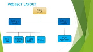
PROJECT LAYOUT
MODULE DISCRIPION
WORKING OPERATION
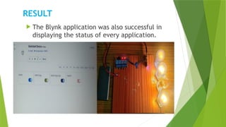
RESULT
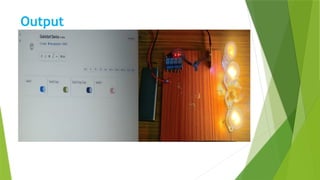
OUT PUT
CONCLUSION
FUTURE SCOPE
3.
Abstract
This projectpresents the overall design of
Home Automation System with low cost and
wireless system.
It specifically focuses on the development of an IOT
based home automation system that is able to control
various components via internet or be automatically
programmed to operate from ambient condition.
We used Node MCU, a popular open source IOT
platform, to execute the process of automation.
4.
INTRODUCTION
Control mostof your home appliances
using laptop or phones remotely.
Get feedback about the status of your
home via internet.
Provide an easily and comfortable way
to control your home devices from any
place.
5.
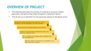
OVERVIEW OF PROJECT
The following describes the process of creating an account in Blynk
application and generating unique ID against a particular device.
This ID acts as an identifier for the particular device on the Blynk server.
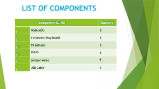
LIST OF COMPONENTS
ComponentSL. NO Quantity
1
Node MCU 1
2
4 channel relay board 1
3.
5V battery 1
4.
BULBS 4
5
Jumper wires 6
6
USB Cable 1
8.
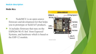
Module description
Node Mcu
NodeMCU is an open-source
firmware and development kit that helps
you to prototype or build IoT products.
It includes firmware that runs on the
ESP8266 Wi-Fi SoC from Espressif
Systems, and hardware which is based on
the ESP-12 module.
9.
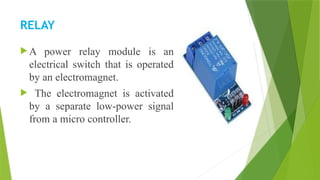
RELAY
A powerrelay module is an
electrical switch that is operated
by an electromagnet.
The electromagnet is activated
by a separate low-power signal
from a micro controller.
10.
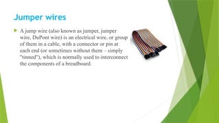
Jumper wires
Ajump wire (also known as jumper, jumper
wire, DuPont wire) is an electrical wire, or group
of them in a cable, with a connector or pin at
each end (or sometimes without them – simply
"tinned"), which is normally used to interconnect
the components of a breadboard.
11.
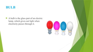
BULB
A bulbis the glass part of an electric
lamp, which gives out light when
electricity passes through it.
12.
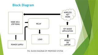
Block Diagram
FIG: BLOCKDIAGRAM OF PROPOSED SYSTEM
NODE MCU
(ESP 8266)
POWER SUPPLY
RELAY
LOAD
IOT BASED
APPLICATION
MOBILE
OR
LAPTOP
WIRELESS
NET
WORK
13.
WORKING OPERATION
NodeMCU is an open source IOT platform.
It includes firmware which runs on the ESP8266
Wi-Fi SoC from Espressif Systems, and hardware
which is based on the ESP-12 module.
The term “Node MCU” by default refers to the
firmware rather than the development kits.
The firmware uses the Lua scripting language.
It is based on the eLua project, and built on the
Espressif Non-OS SDK for ESP8266.
14.
ADVANTAGES
SAVE MONEYAND INCREASES CONVENIENCE
SAVE TIME
HIGH RELABILIATY
EASY TO CONTROL
CONCLUSTION
By usingthis we can reduce cost and
can control or monitoring the home
appliances from anywhere
Can create wireless network in house
and reduce wiring.
Hence, this system is scalable and
flexible.
19.
FUTURE SCOPE
Usingthis system as framework, the system can be expanded to
include various other options which could include home security
feature like capturing the photo of a person moving around the
house and storing it onto the cloud.
This will reduce the data storage than using the CCTV camera
which will record all the time and stores it. The system can be
expanded for energy monitoring