Contents:
Abstract
Literaturesurvey
Components
Explanation of every Component
Block diagram
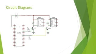
Circuit diagram
Working
Connections
Sample code
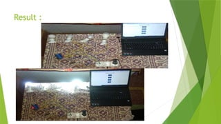
Result
Conclusion
3.
Abstract :
In themodern era, smart home technology has emerged as a crucial element in
enhancing the convenience, security, and energy efficiency of residential environments.
This project focuses on designing and implementing a Home Automation System using
NodeMCU ESP8266, aimed at revolutionizing the way homeowners interact with their
household devices. By leveraging the capabilities of the Internet of Things (IoT), the
system provides remote control and monitoring of various home appliances, ensuring a
seamless integration of technology into everyday life
4.
Literature survey:
The expeditiouslygrowing internet has opened new horizons for development in
various fields. The home automation industry has seen a rapid growth in the previous years.
It has become a topic of interest for many people around the world. Vishwateja Mudiam
Reddy & Naresh Vinay in their paper “Internet of Things Enabled Smart Switch” designed a
system which integrates the cloud and web app.
With the assistance of flip-flops, logic gates and a processor, the switches might be
controlled. The proposed model was intended for reducing the value of those systems which
was the most barrier within the wide adaptation of this technology. Khusvinder Gill &
Shuang-Hua Yang created a common home gateway for ZigBee and Wi-Fi. This enables a
remote control using a simple graphical user interface. The system was cost effective and
had a good security inside the house.Salma and Dr. Radcliffe with a goal of increasing the
popularity and reach of home automation designed a system that used the Novel Network
Protocol. It gave the choice of controlling the commercial devices through a mobile phone
or laptop. An additional network device had been used for remote access in place of a
microcontroller.
5.
Components:
Hardware Requirements:
1.NODE MCU ESP8266
2. 4- Channel relay module
3. Bread board
4. Jumper wires
5. 5 V 1 Amps AC To DC Adapter
Software Requirements :
1. Arduino IDE – Compiler
2. Language – Embedded C
6.
Explanation of everyComponent:
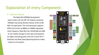
NODE MCU ESP8266:
The Node MCU ESP8266 development
board comes with the ESP-12E module containing
ESP8266 chip having Tensilica Xtensa 32-bit LX106
RISC microprocessor. This microprocessor supports
RTOS and function at 80MHz to 160MHz adjustable
clock frequency. Node MCU has 128 KB RAM and 4MB
of non-volatile storage to store data and programs.
Its higher processing power with the in-built Wi-Fi /
Bluetooth and Deep Sleep Operating features makes
it best for IoT projects.
7.
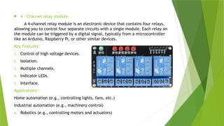
4 –Channel relay module:
A 4-channel relay module is an electronic device that contains four relays,
allowing you to control four separate circuits with a single module. Each relay on
the module can be triggered by a digital signal, typically from a microcontroller
like an Arduino, Raspberry Pi, or other similar devices.
Key Features:
1. Control of high voltage devices.
2. Isolation.
3. Multiple channels.
4. Indicator LEDs.
5. Interface.
Applications :
Home automation (e.g., controlling lights, fans, etc.)
Industrial automation (e.g., machinery control)
6. Robotics (e.g., controlling motors and actuators)
8.
5V 1AMPS AC To DC ADAPTER:
This AC to DC power supply will do 5V at 1A! They’re switch mode power
supplies which means the output is regulated to 5V (no more 14V outputs!).
These have a standard USB ‘A’ connector for the output so you can power your
Arduino, Raspberry Pi, etc. through a USB
Specifications :
Input Voltage (V): 100 ~ 280 VAC @50 ~ 60Hz.
Input current (mA): 100.
Output Power: 5V 1A.
Input Plug: 2-Pin EU type.
Output Plug: 5.5mm DC plug.
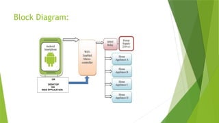
Working:
The heart ofthis project is the WiFi enabled board that needs no introduction;
the ESP8266 based Node MCU development board. It is an open source platform for
developing WiFi based embedded systems and it is based on the popular ESP8266
WiFi Module, running the Lua based Node MCU firmware. Node MCU was born out
of the desire to overcome the limitations associated with the first versions of the
ESP8266 module which was not compatible with breadboards, it was difficult to
power and even more difficult to program. The Node MCU board is easy to use, low
cost and that quickly endeared it to the heart of makers and it is one of the most
popular boards today.
For this project, we will add a 4-channel relay module to the ESP8266 board.
The project flow involves the control of Node MCU’s GPIOs from a webpage on any
device connected on the same network as the board. The status of the GPIOs
control the coils of the relays and that causes the relay to alternate between
normally open (NO) and normally closed (NC) condition depending on the state of
the GPIO, thus, effectively turning the connected appliance “ON” or “OFF”.
12.
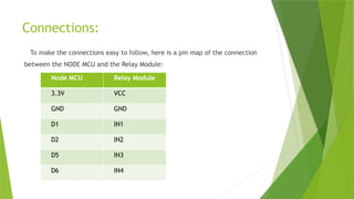
Connections:
To make theconnections easy to follow, here is a pin map of the connection
between the NODE MCU and the Relay Module:
Node MCU Relay Module
3.3V VCC
GND GND
D1 IN1
D2 IN2
D5 IN3
D6 IN4
Conclusion:
Based on theresults of analysis of all data obtained by testing the smart home with the
Internet of Things based Node MCU ESP6288 module, the following conclusions can be
drawn:
1) Smart Home with Internet of Things (IoT) based Node MCU ESP8266 Module can be
designed with various components hardware and software support so that it can be arranged
into a smart home system that is controlled with the Web application according to what is
intended.
2) The Smart Home with this Internet of Things (IoT) based Node MCU ESP8266 Module can
be implemented to control some of the home electronics performance including lighting
controls, fan control, temperature monitoring, early warning systems and etc.
3) Main purpose of home automation system is to provide ease to people to control different
home appliances with the help of the web application using their mobile phones or desktop
and to save time and money.