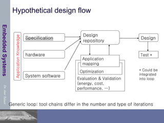
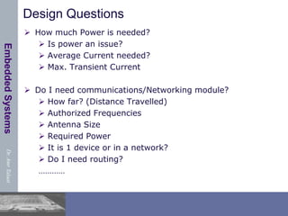
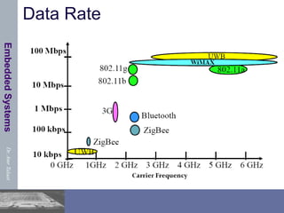
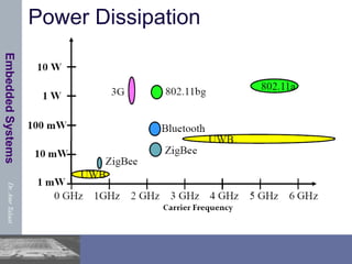
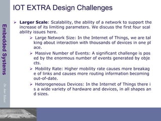
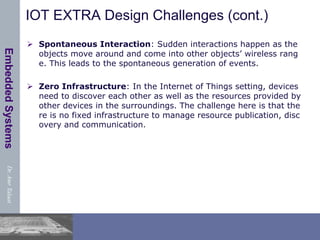
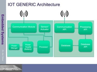
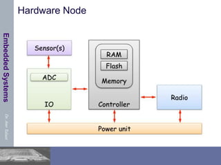
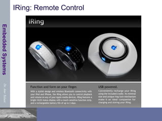
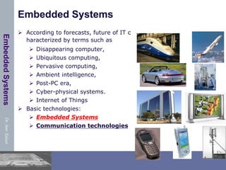
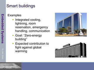
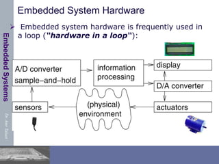
This document provides an overview of embedded systems and Internet of Things (IoT) design. It defines embedded systems as information processing systems embedded into larger products. Future technologies are expected to involve ubiquitous and ambient computing through cyber-physical systems connected by the IoT. Basic technologies will include embedded systems and communication. Embedded systems must be dependable, efficient to meet real-time constraints, and dedicated to specific applications while optimizing various design metrics like size, performance, and cost. Additional challenges in IoT design involve scalability for large networks of heterogeneous devices with spontaneous interactions. Typical embedded system hardware includes microcontrollers with RAM, EEPROM, flash memory and communication modules.

![Dr.
Amr
Talaat
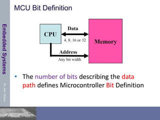
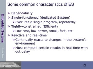
Embedded
Systems
Embedded Systems & Cyber-Physical Systems
“Dortmund“ Definition: [Peter Marwedel]
Embedded systems are information processing systems
embedded into a larger product
Berkeley: [Edward A. Lee]:
Embedded software is software integrated with physical
processes. The technical problem is managing time and
concurrency in computational systems.
Definition: Cyber-Physical (cy-phy) Systems (CPS)
are integrations of computation with physical
processes [Edward Lee, 2006].](https://image.slidesharecdn.com/iotes-240221164327-400a9501/85/IOT-based-embedded-systems-using-arduino-5-320.jpg)

![Dr.
Amr
Talaat
Embedded
Systems
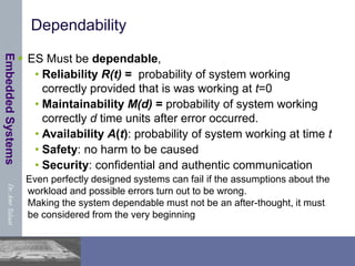
Real-time constraints
Many ES must meet real-time constraints
A real-time system must react to stimuli from the con
trolled object (or the operator) within the time interv
al dictated by the environment.
For real-time systems, right answers arriving too late
are wrong.
“A real-time constraint is called hard, if not me
eting that constraint could result in a catastrop
he“ [Kopetz, 1997].
All other time-constraints are called soft.
A guaranteed system response has to be explained w
ithout statistical arguments](https://image.slidesharecdn.com/iotes-240221164327-400a9501/85/IOT-based-embedded-systems-using-arduino-16-320.jpg)
![Dr.
Amr
Talaat
Embedded
Systems
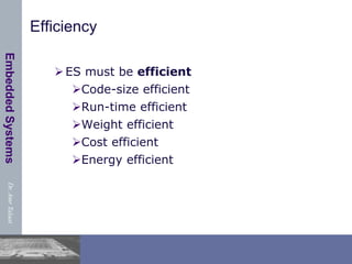
Reactive & hybrid systems
Typically, ES are reactive systems:
“A reactive system is one which is in continual interacti
on with is environment and executes at a pace determi
ned by that environment“ [Bergé, 1995]
Behavior depends on input and current state.
automata model appropriate,
model of computable functions inappropriate.
Hybrid systems
(analog + digital parts).](https://image.slidesharecdn.com/iotes-240221164327-400a9501/85/IOT-based-embedded-systems-using-arduino-18-320.jpg)