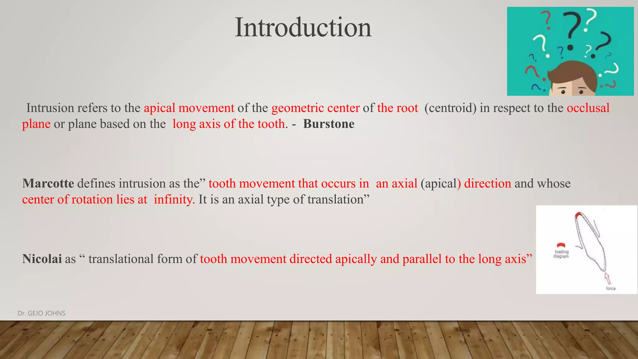
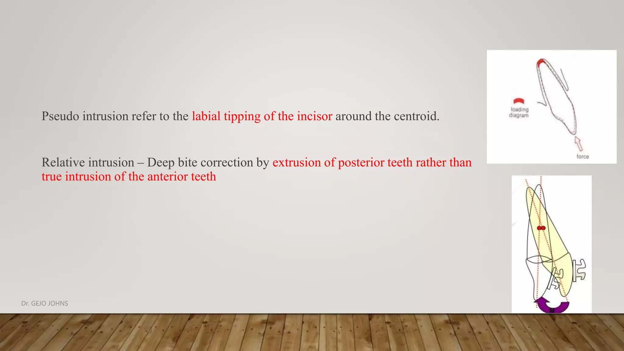
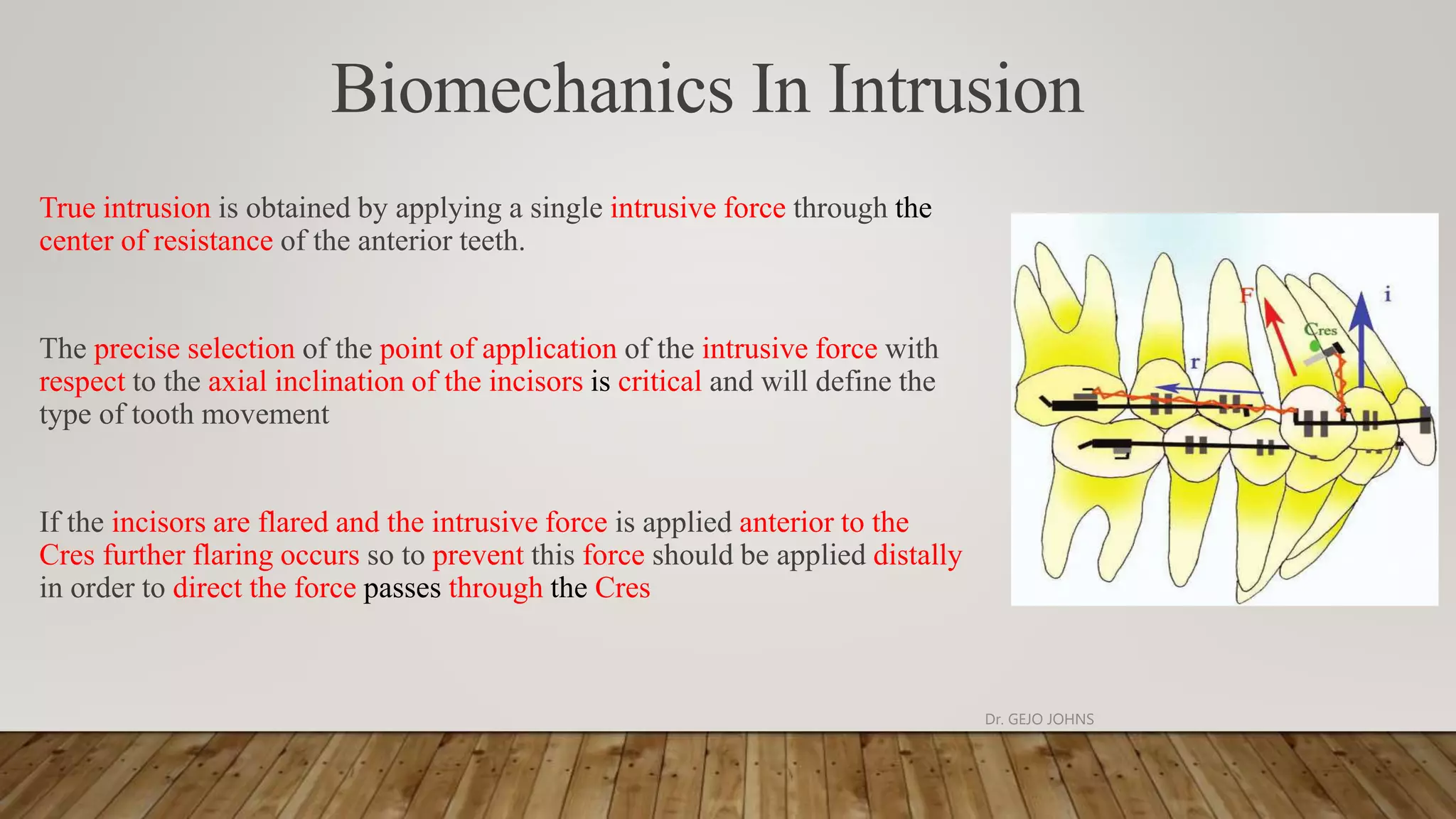
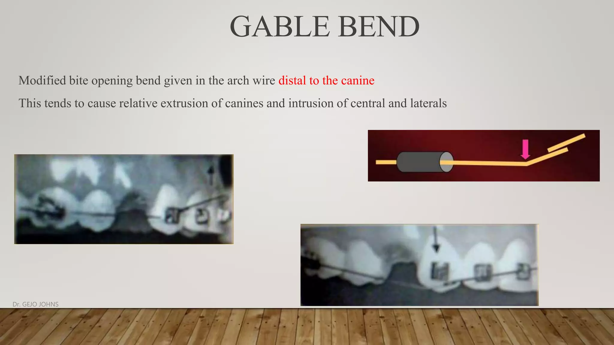
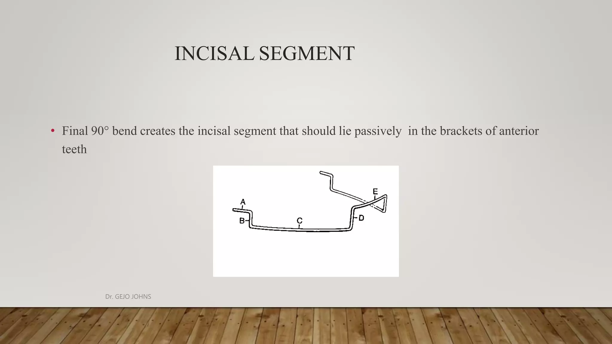
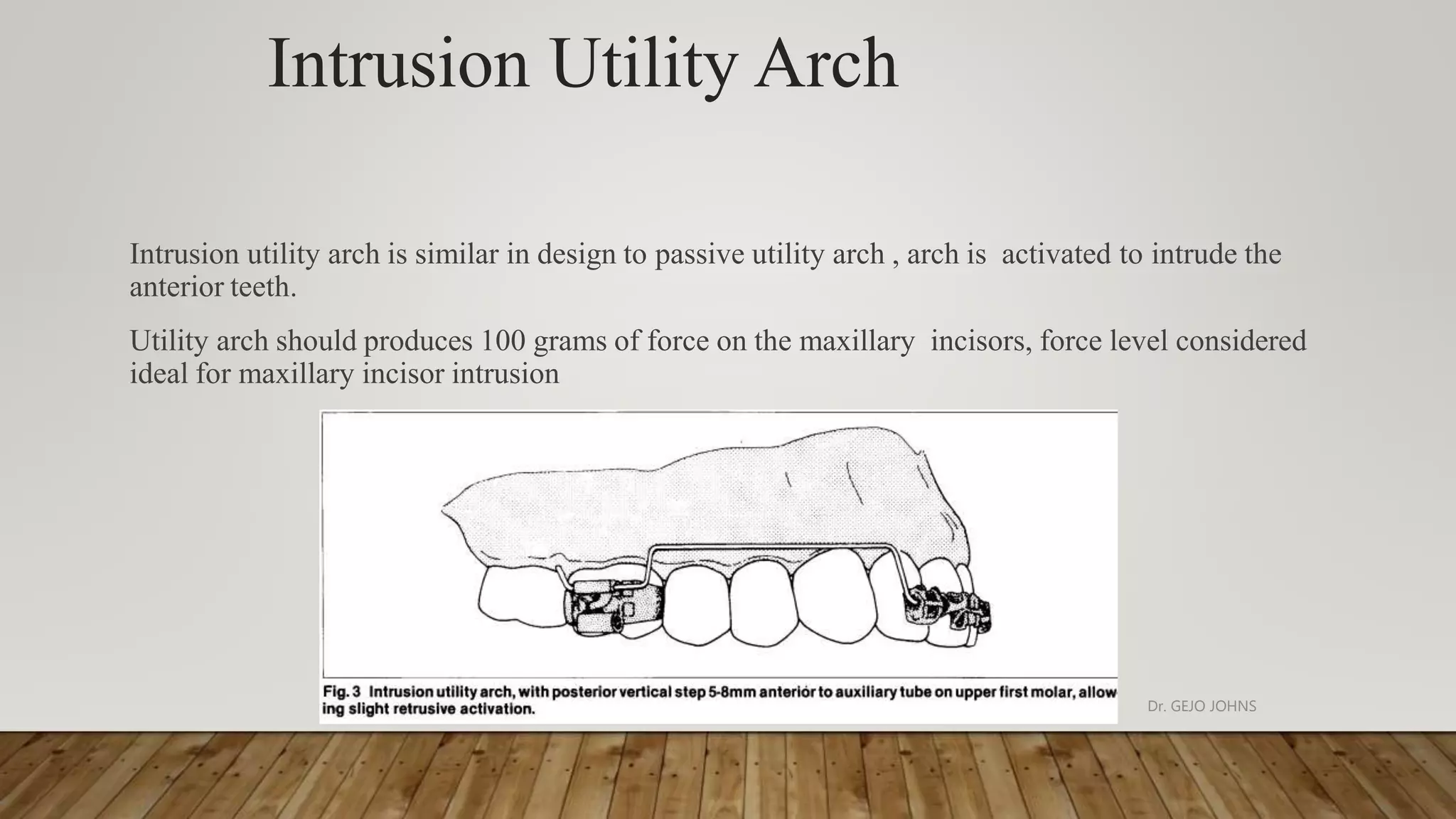
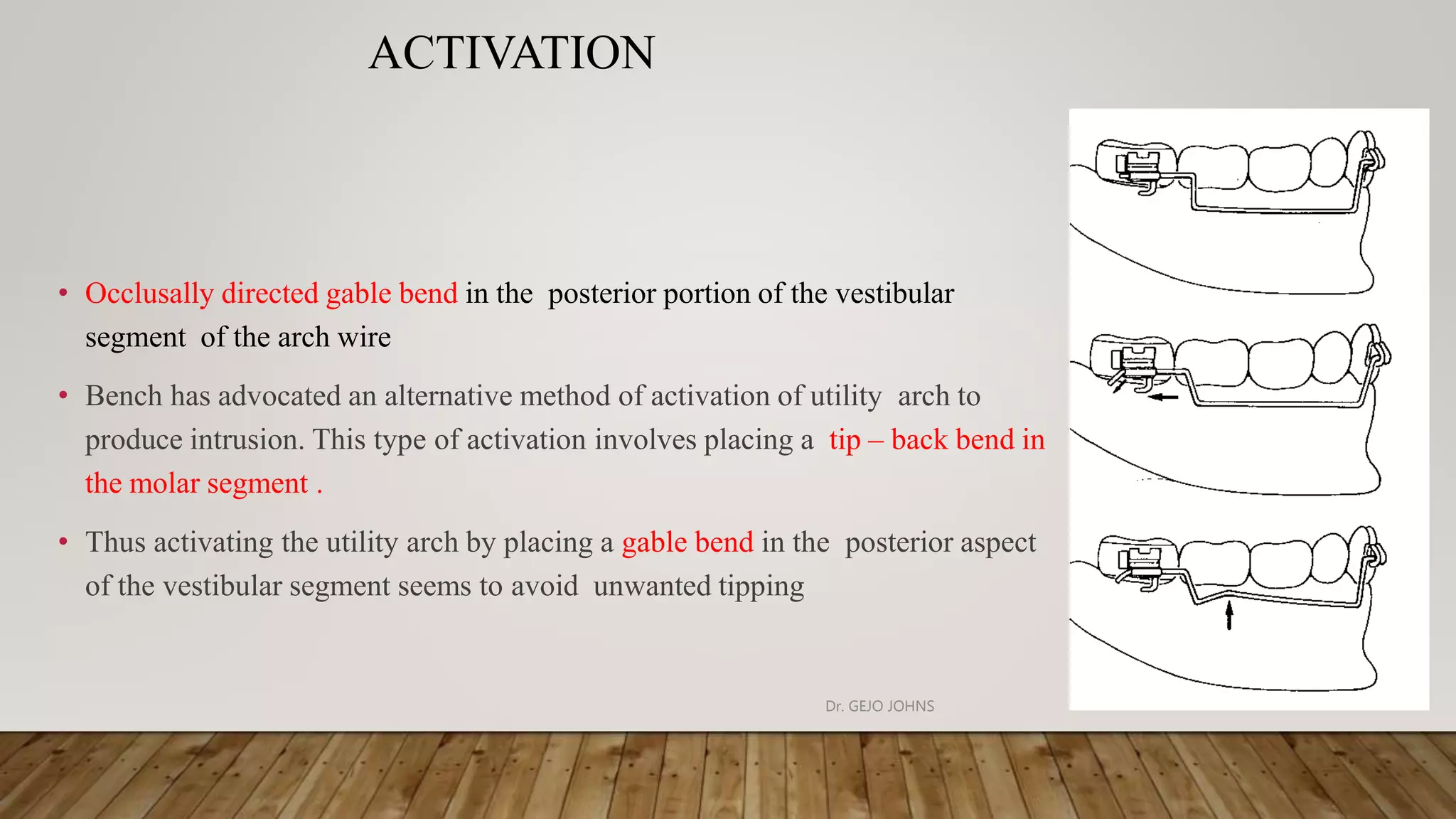
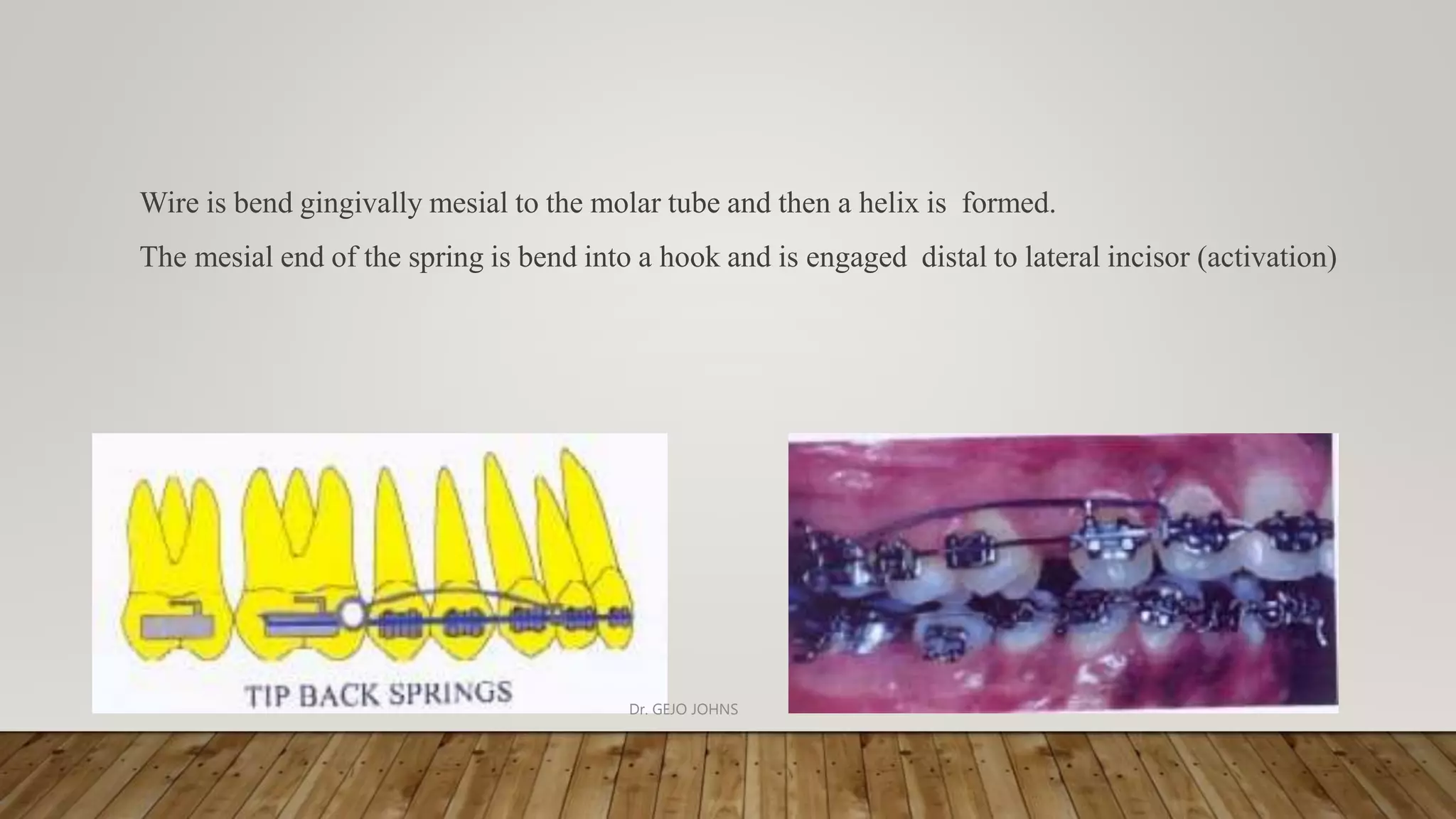
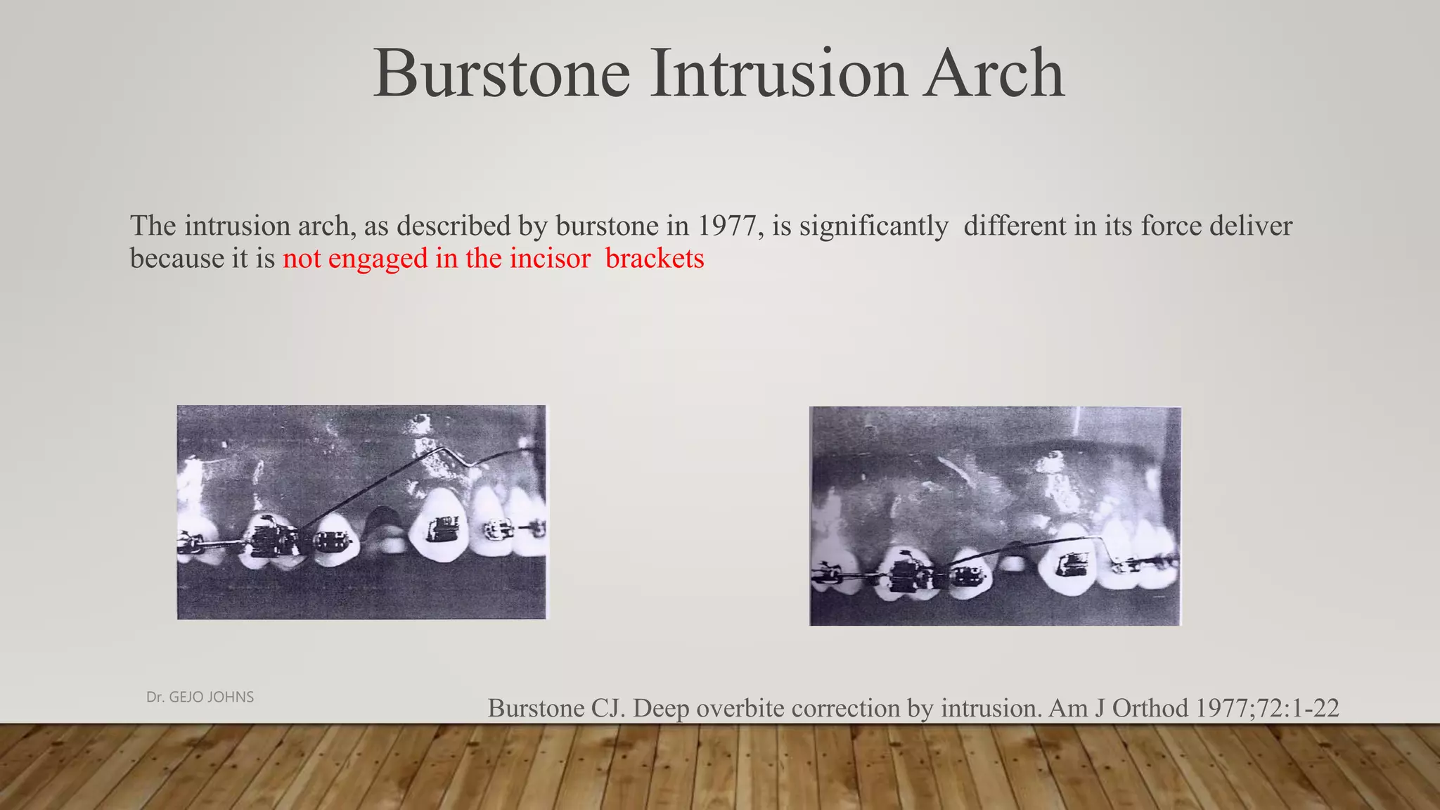
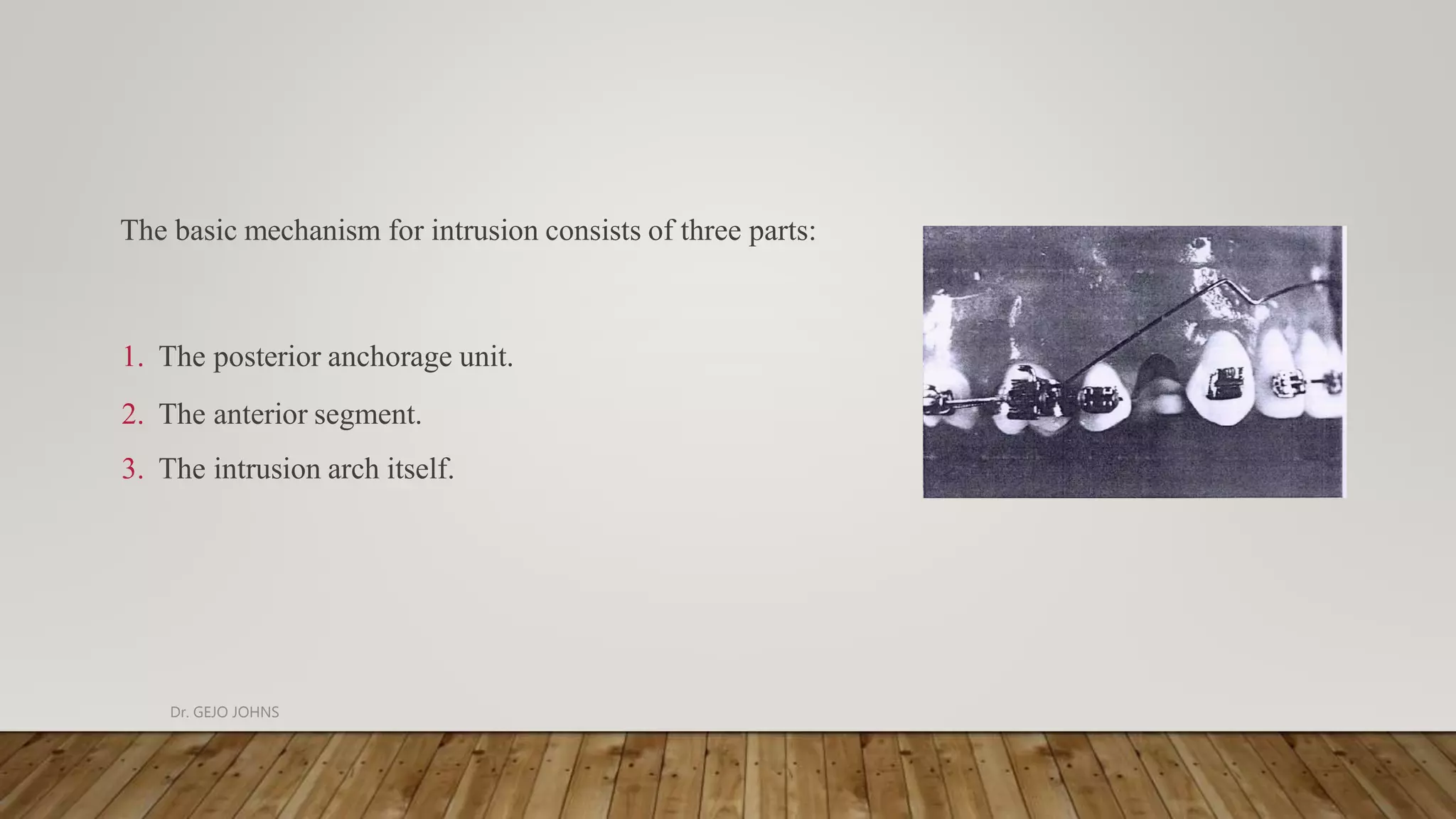
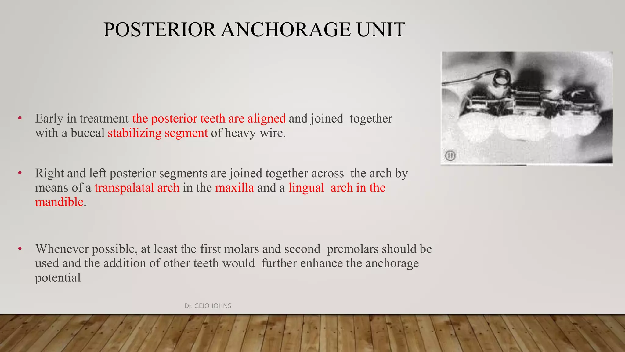
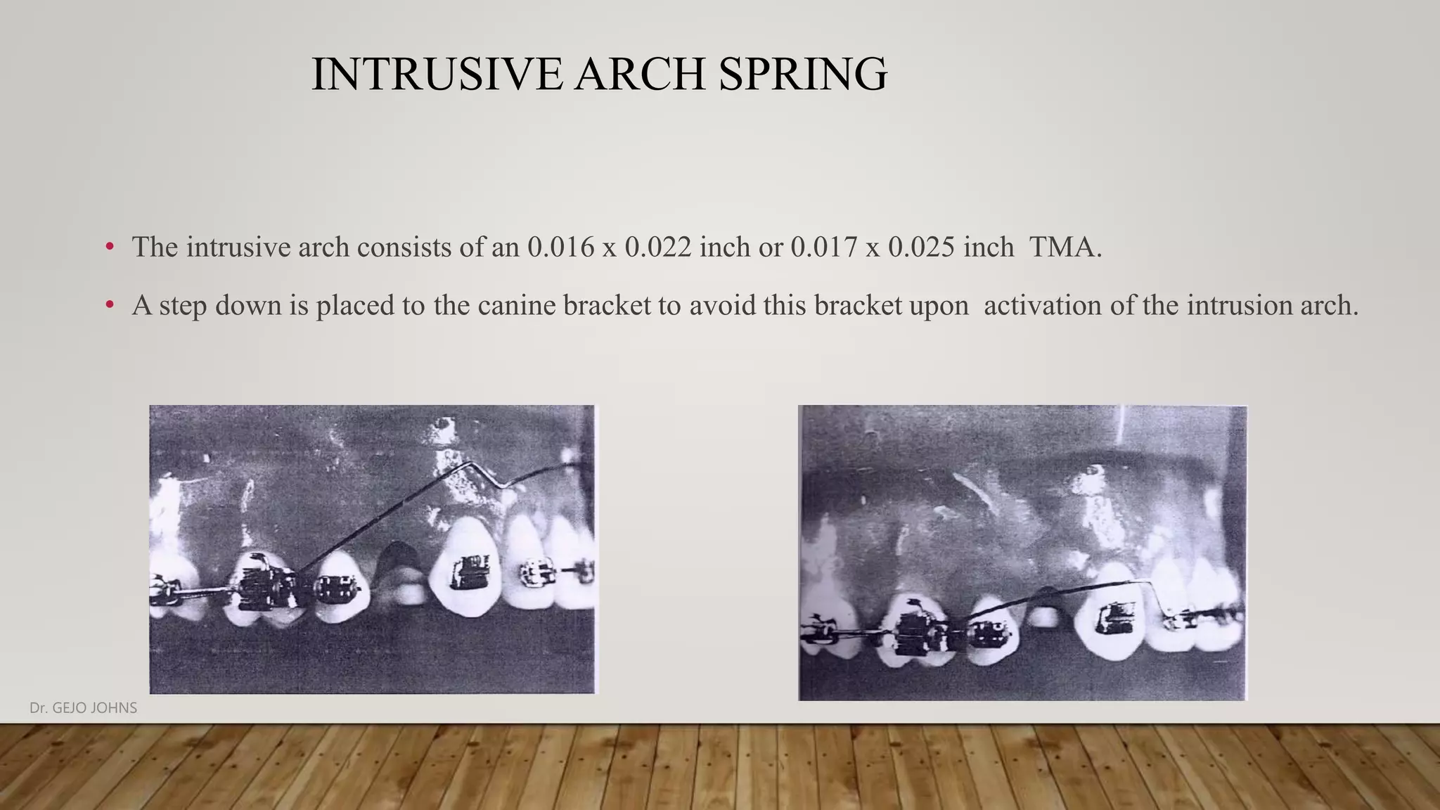
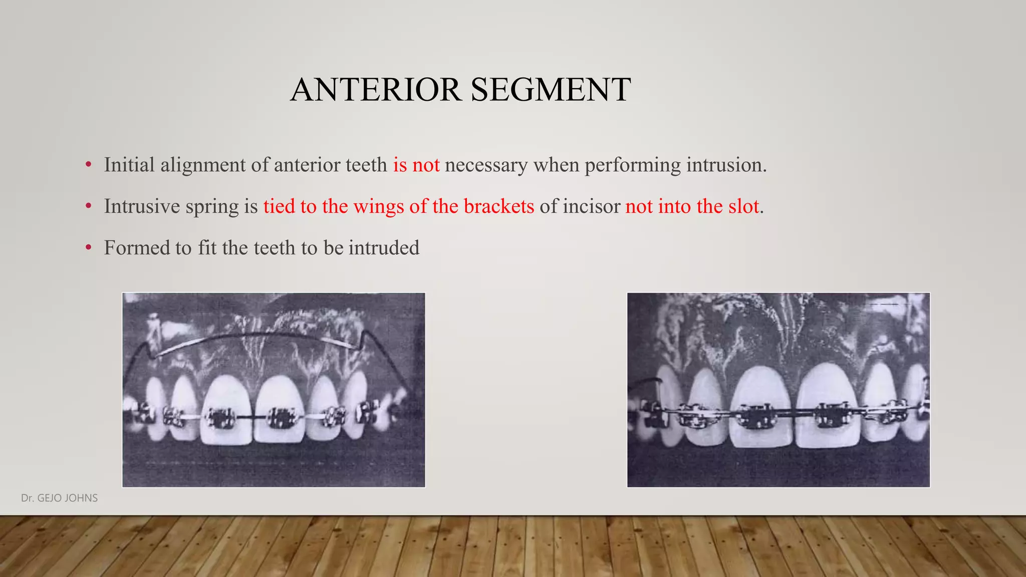
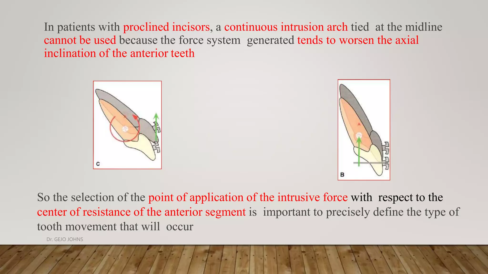
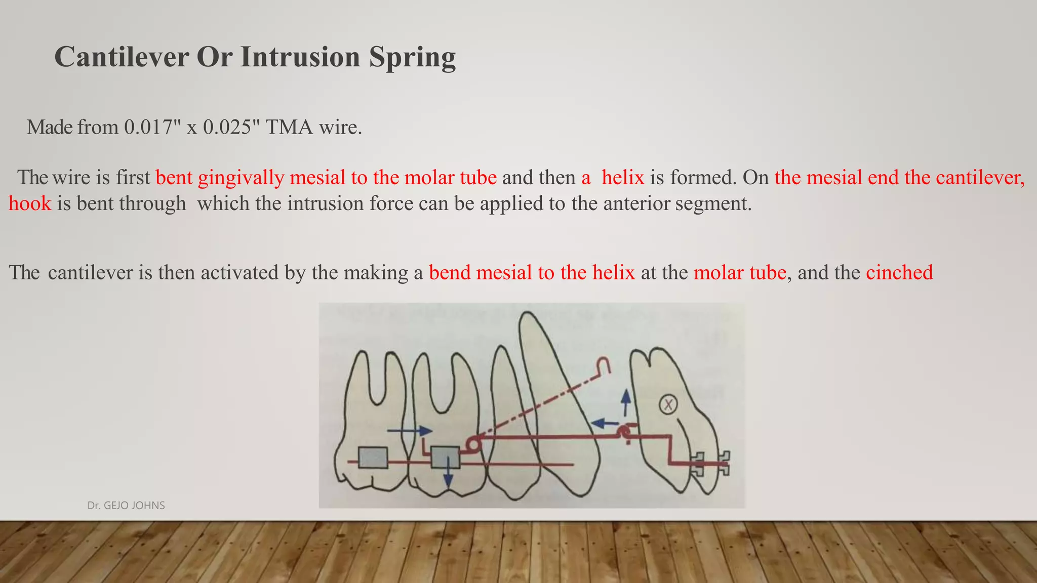
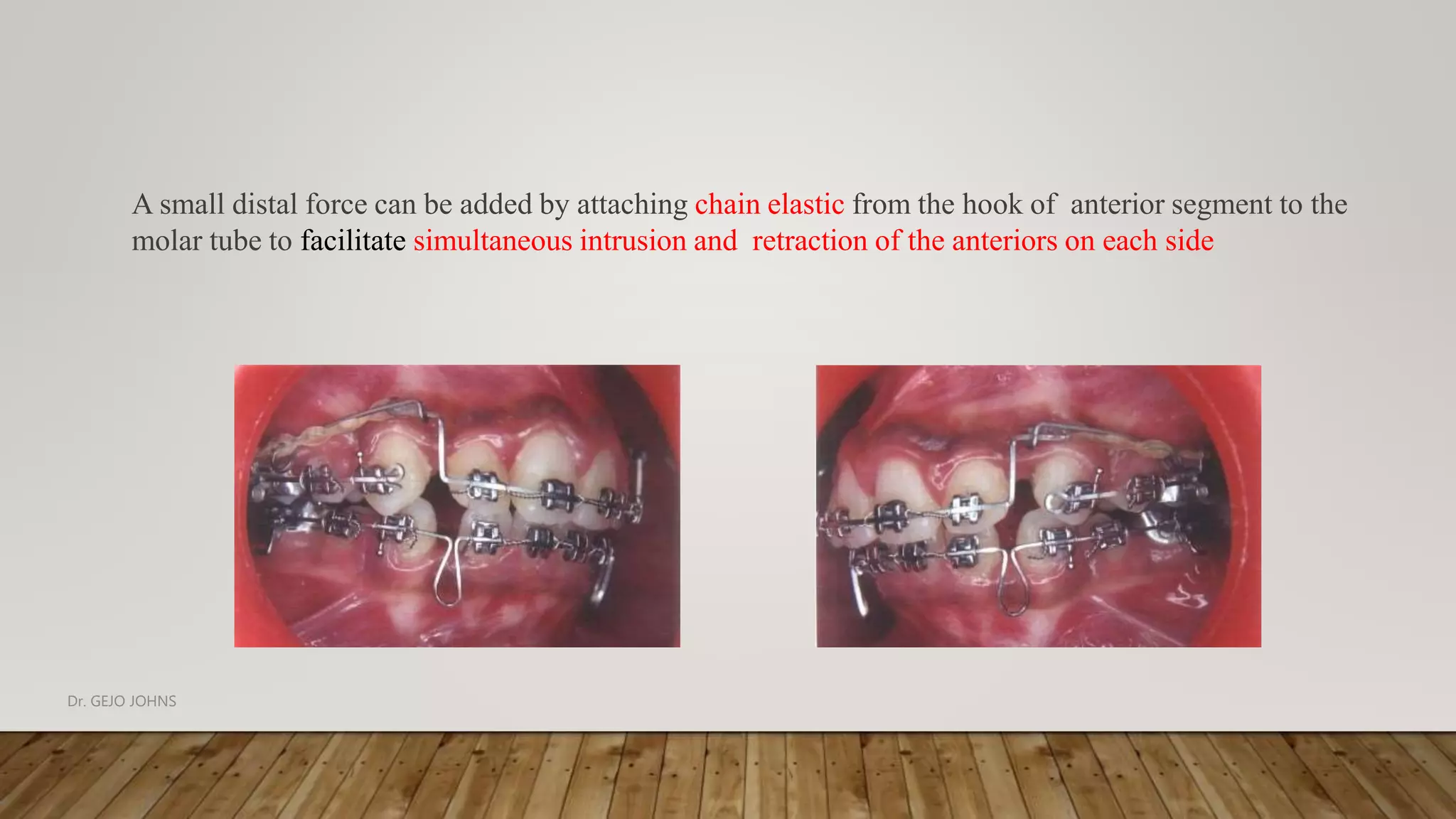
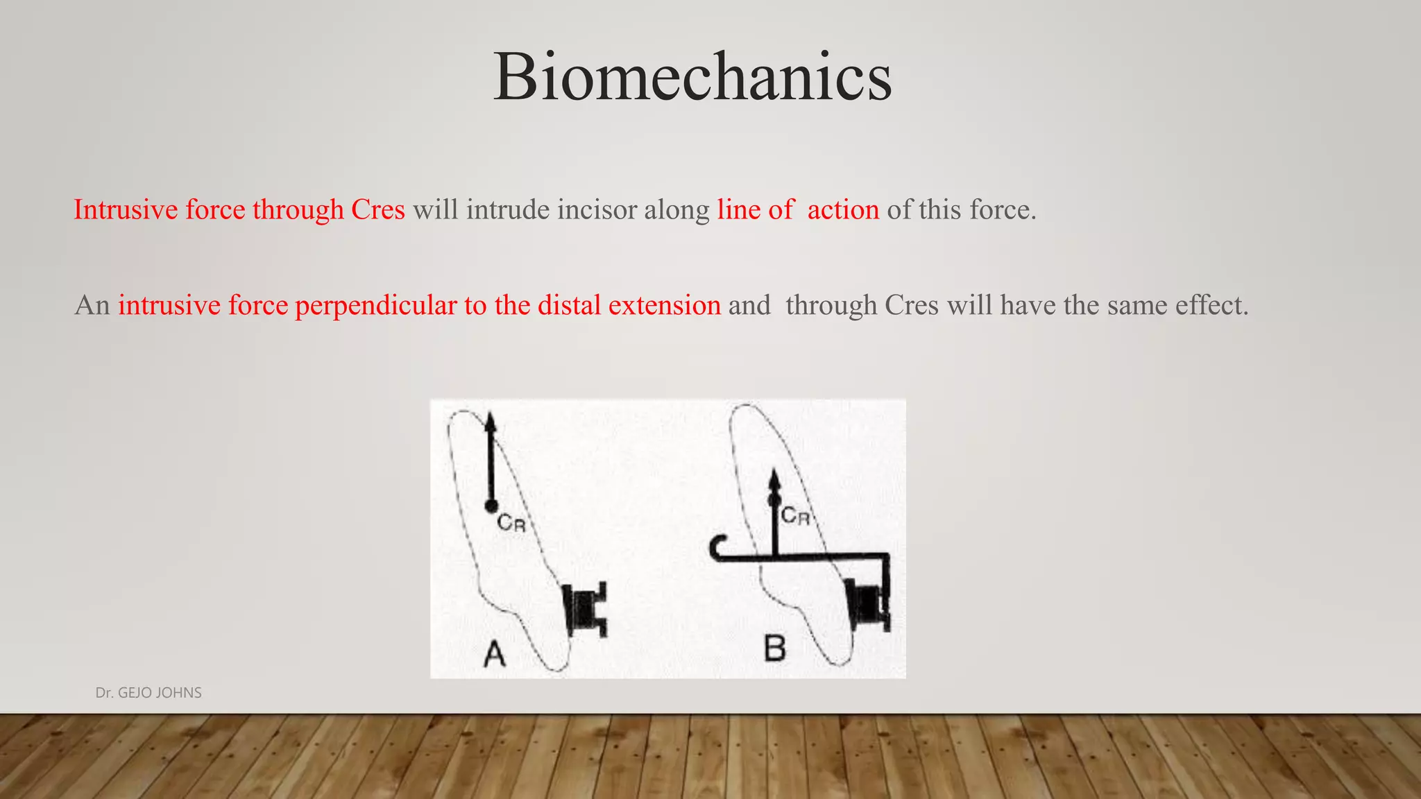
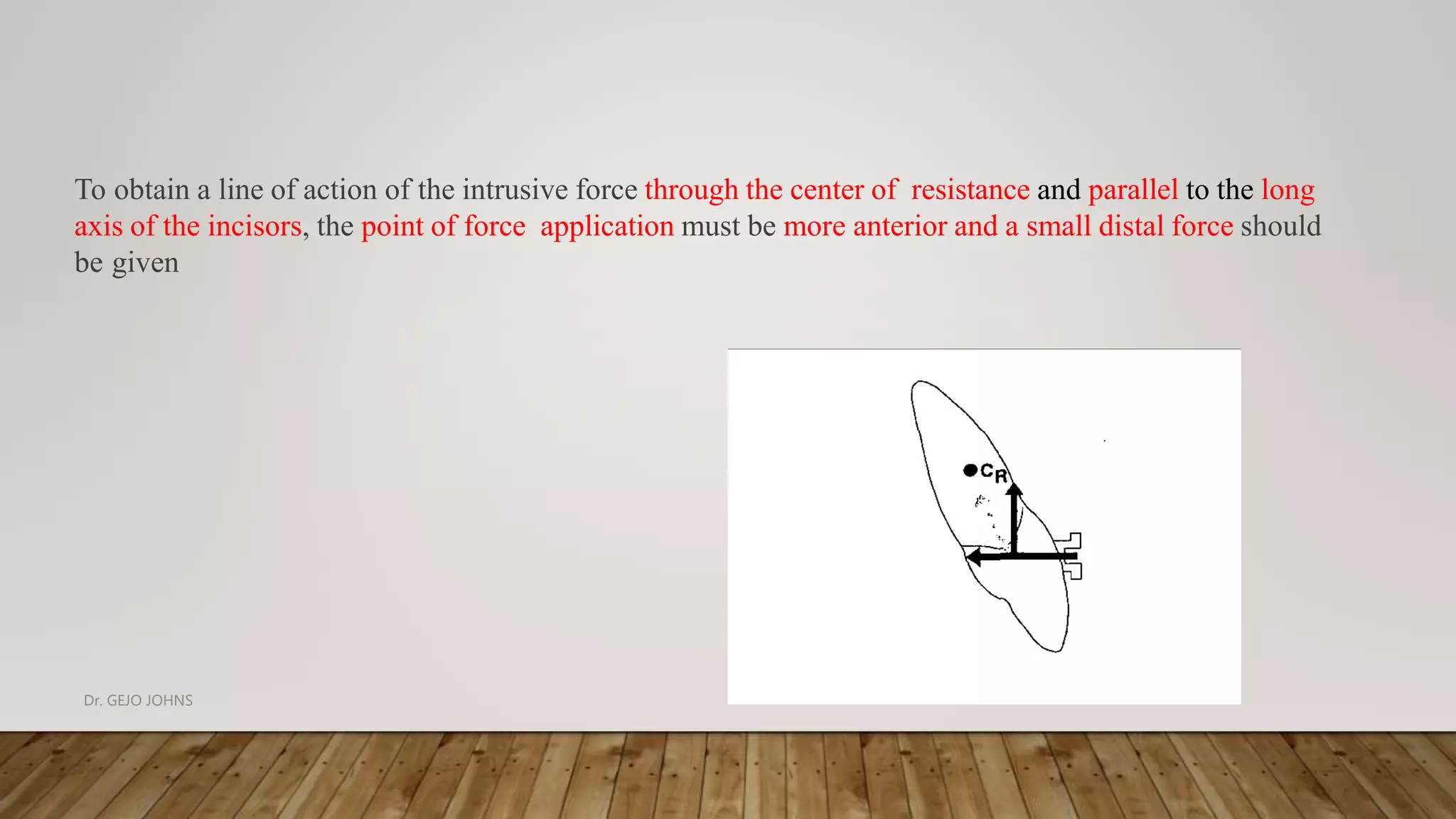
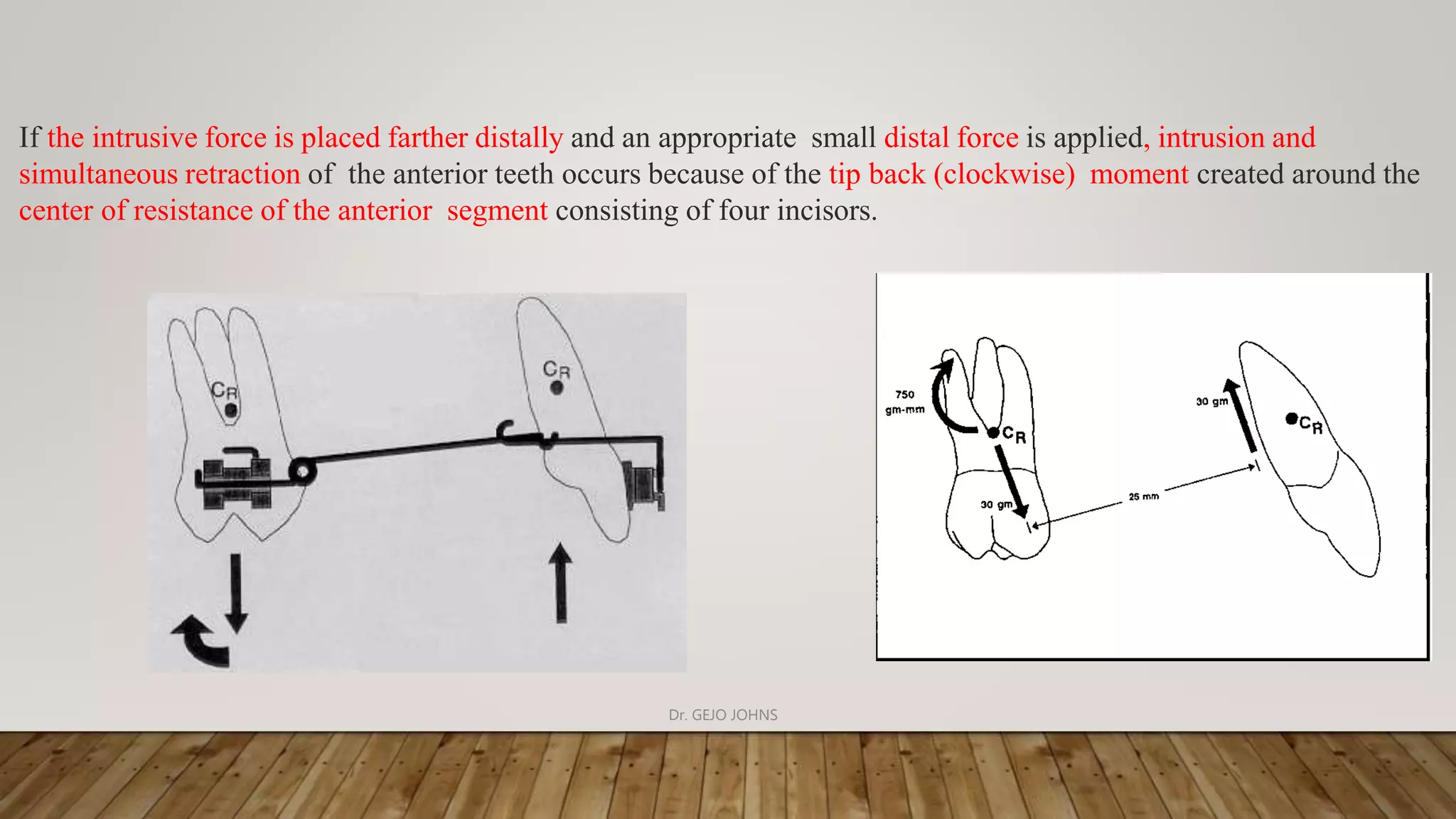
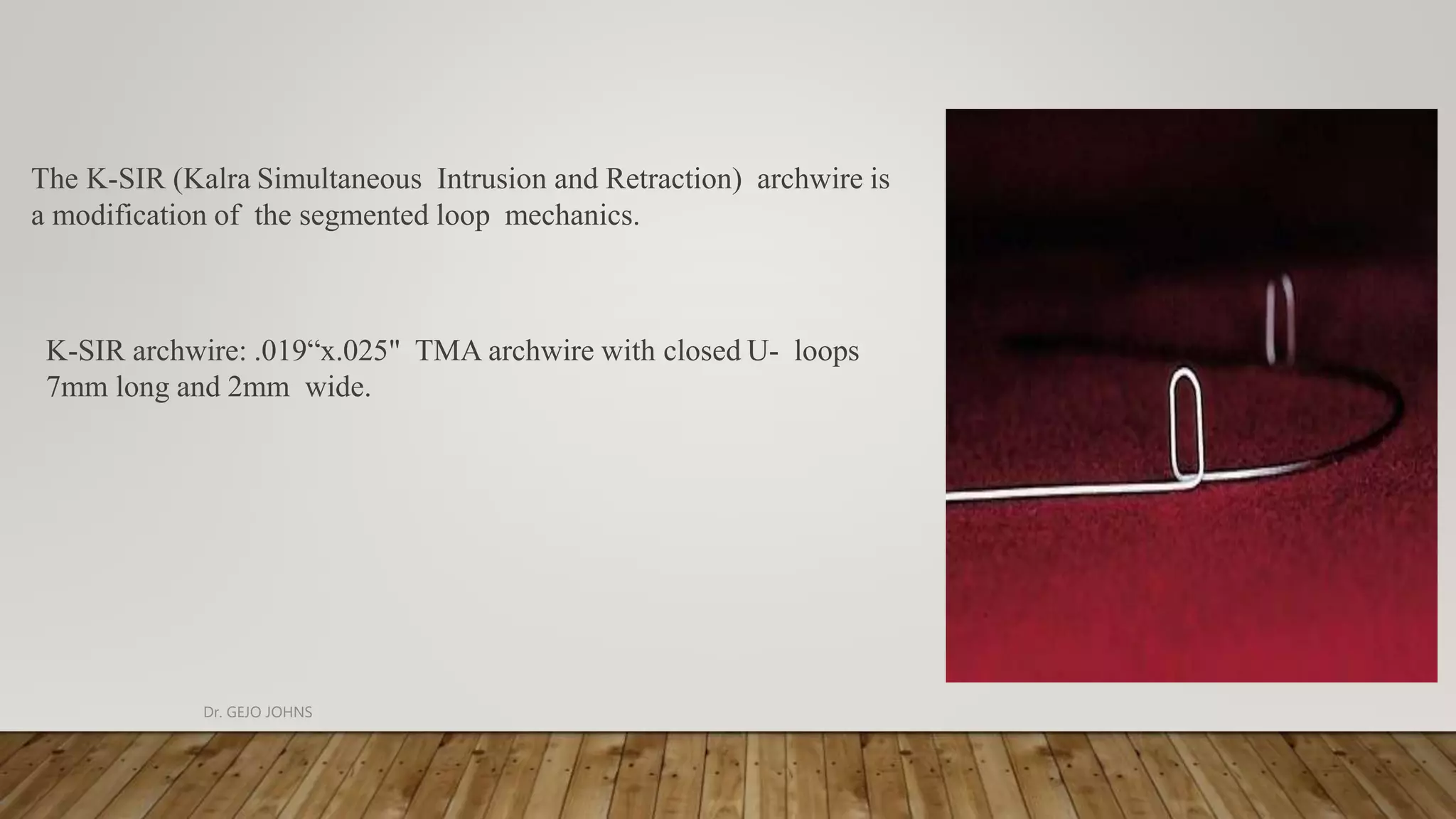
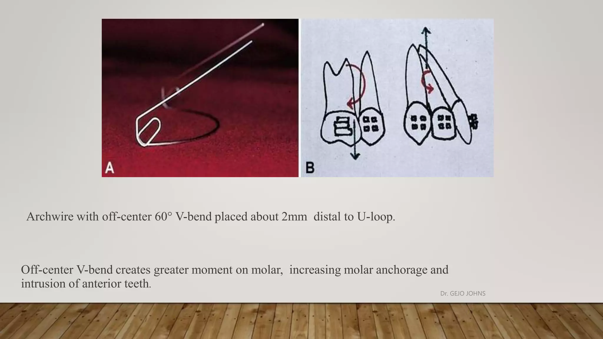
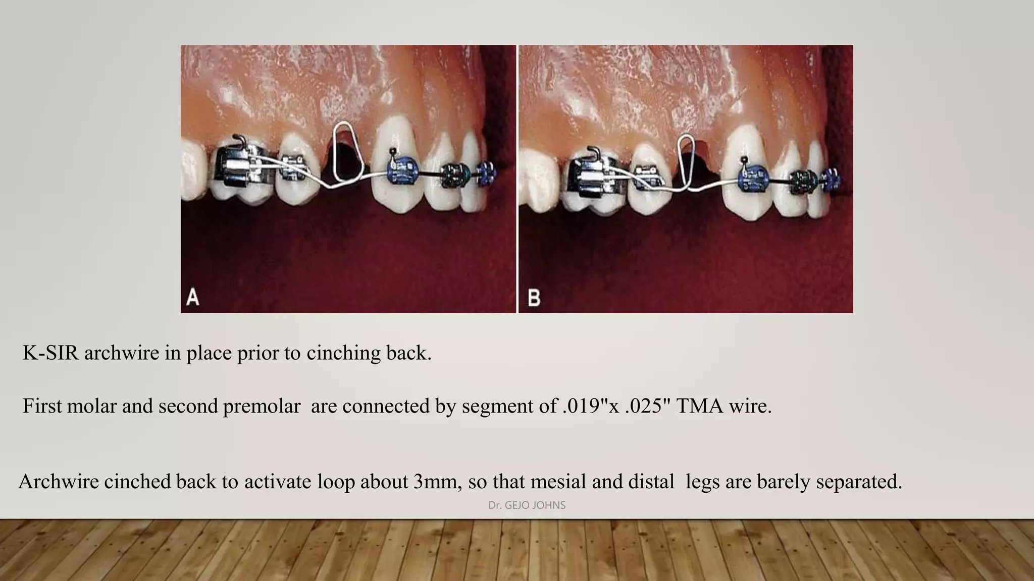
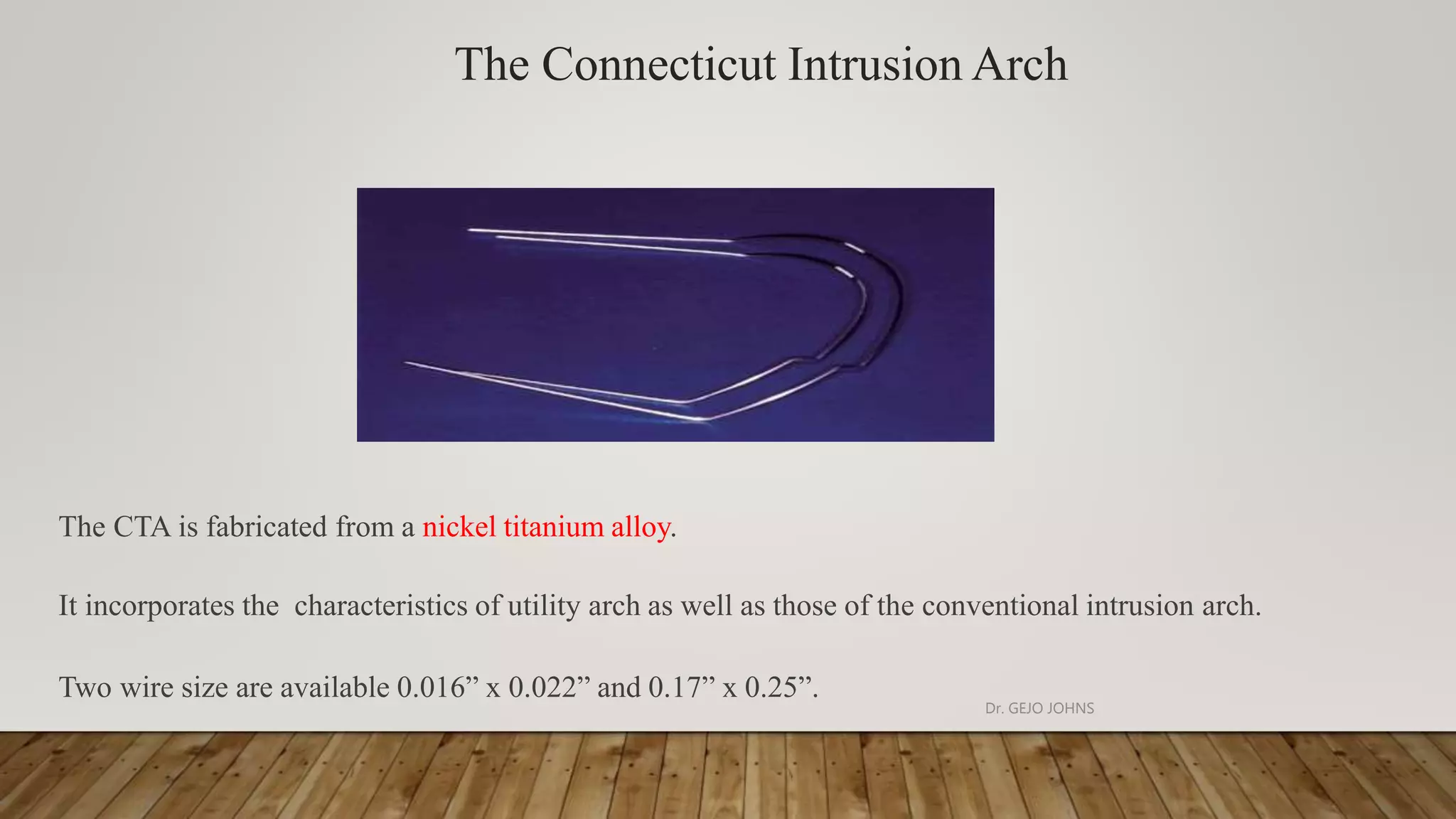
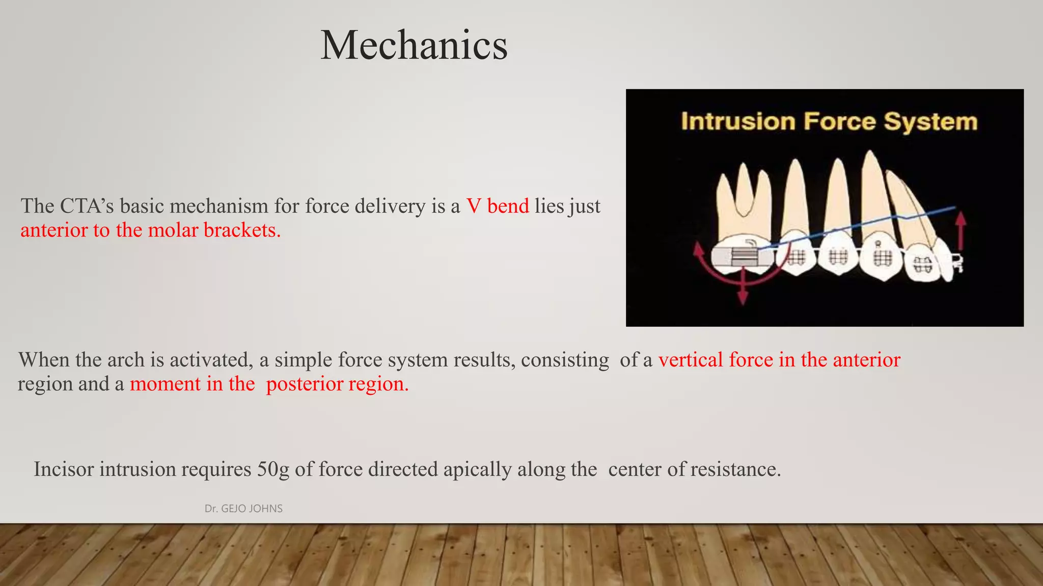
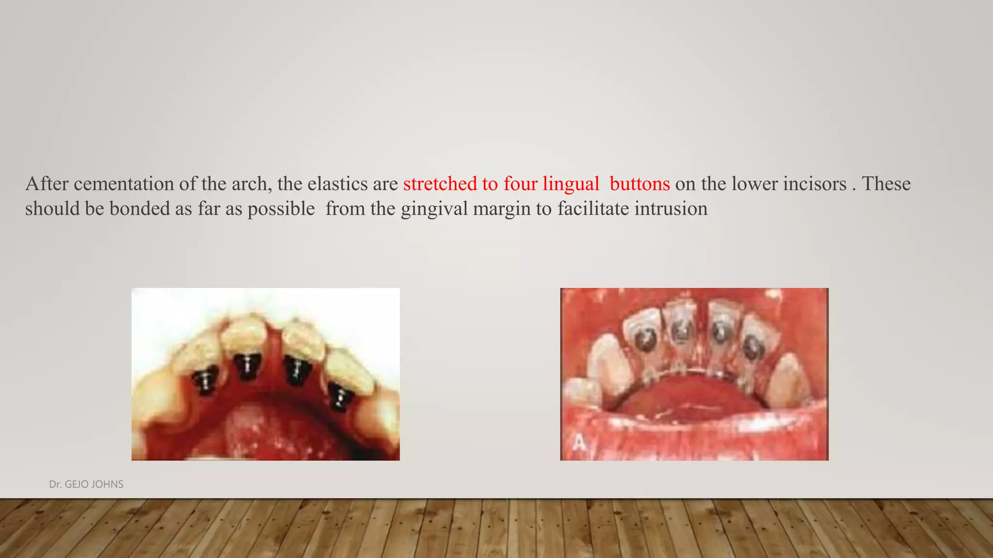
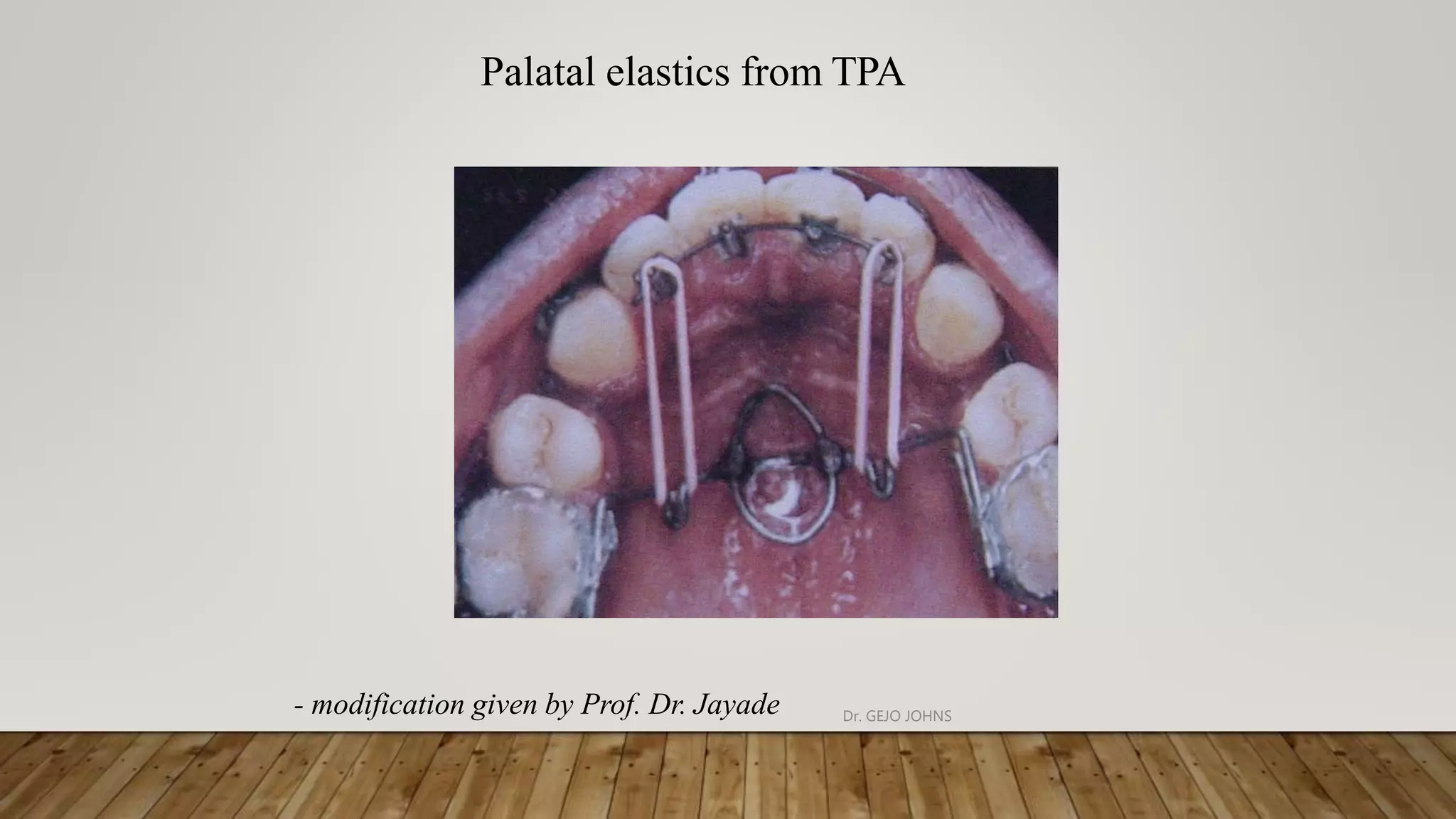
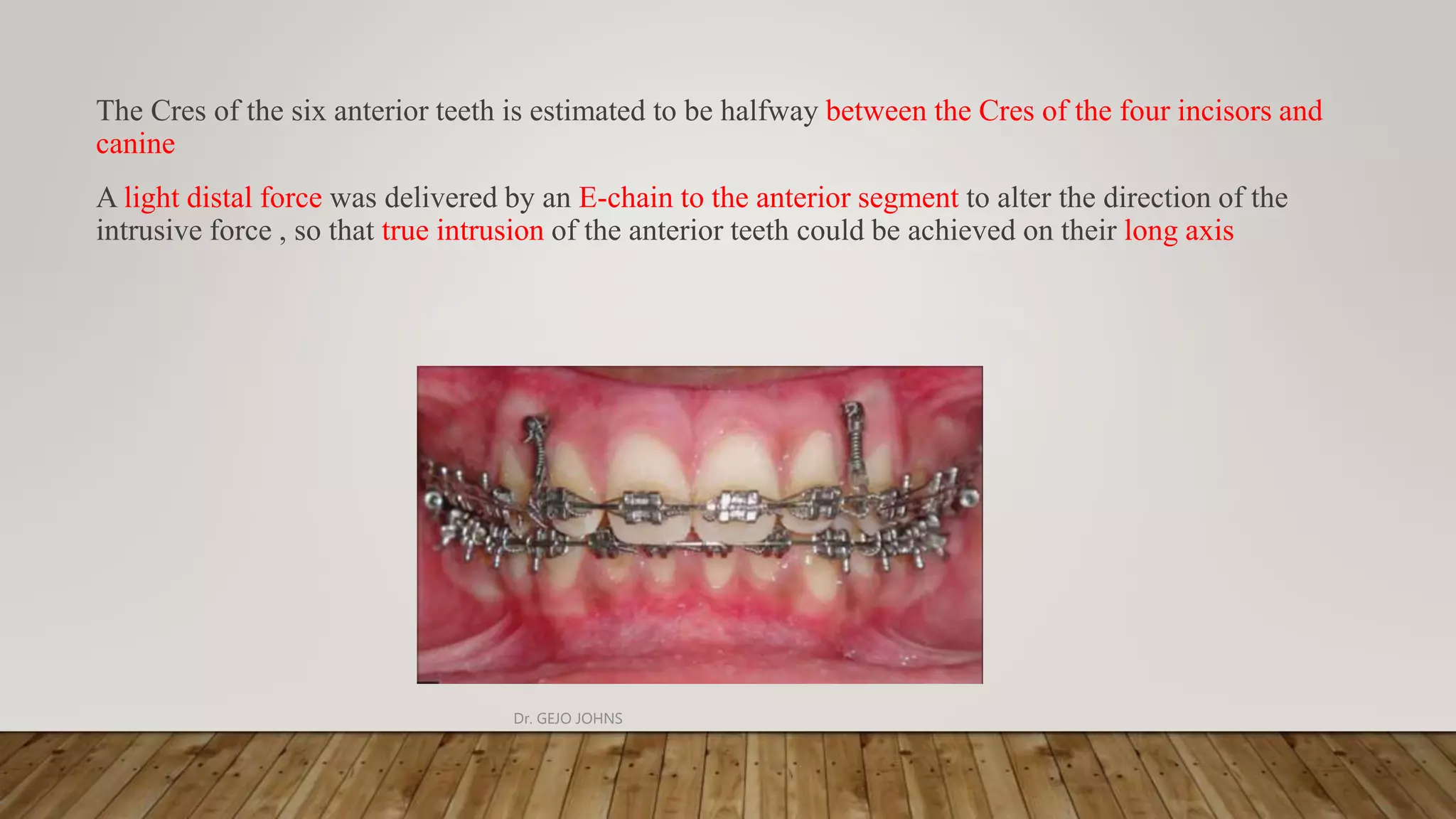
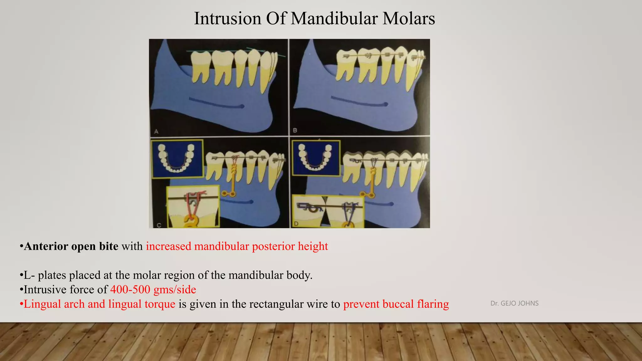
INTRUSION MECHANICS IN ORTHODONTICS
BY
Dr. GEJO JOHNS
Dr. GEJO JOHNS
CONTENTS
1. Introduction
2. Major principles of intrusion
3. Biomechanics involved
4. Various intrusion appliances
A. Head gear
B. Rickett’s utility arch
C. Tipback springs ( intrusion springs)
D. Burstone’s continuous intrusion arch.
E. Burstone’s three piece intrusion arch
F. K-sir (kalra simultaneous intrusion and retraction)
G. Connecticut intrusion arch
H. PG retraction spring
I. Translation arch
J. Lingual arch for intruding and uprighting lower incisors
K. Temporary Anchorage Devices
5. References
Dr. GEJO JOHNS
Introduction
Intrusion refers to the apical movement of the geometric center of the root (centroid) in respect to the occlusal
plane or plane based on the long axis of the tooth. - Burstone
Marcotte defines intrusion as the” tooth movement that occurs in an axial (apical) direction and whose
center of rotation lies at infinity. It is an axial type of translation”
Nicolai as “ translational form of tooth movement directed apically and parallel to the long axis”
Dr. GEJO JOHNS
Correction of the deep overbite can be accomplished in a number of ways depending on the initial
diagnosis and treatment objectives. Deep bite can be corrected by various tooth movements which
include:
 Extrusion of posterior teeth
 Uprighting of posterior teeth
 Increasing the inclination of incisors
 Intrusion of anterior teeth
 Combination of one or two of the above tooth movements
Dr. GEJO JOHNS
Extrusion of the posterior teeth will result in increased lower facial height, steepening of the
occlusal plane, downward and backward rotation of the mandible, resulting in worsening of the
class II skeletal relationship.
Intrusion of anterior teeth to correct deep overbite may be indicated in patients with unaesthetic
excessive maxillary incisor showing at rest position of the lip (5-8mm)
Dr. GEJO JOHNS
Pseudo intrusion refer to the labial tipping of the incisor around the centroid.
Relative intrusion – Deep bite correction by extrusion of posterior teeth rather than
true intrusion of the anterior teeth
Dr. GEJO JOHNS
Biomechanics In Intrusion
True intrusion is obtained by applying a single intrusive force through the
center of resistance of the anterior teeth.
The precise selection of the point of application of the intrusive force with
respect to the axial inclination of the incisors is critical and will define the
type of tooth movement
If the incisors are flared and the intrusive force is applied anterior to the
Cres further flaring occurs so to prevent this force should be applied distally
in order to direct the force passes through the Cres
Dr. GEJO JOHNS
Major Principles Of Intrusion
Six major principle of intrusion should be followed; if genuine intrusion and greater control of force system is
needed:
1. Controlling force magnitude and constancy.
2. Anterior single point contacts.
3. Point of force application.
4. Selective intrusion.
5. Control of reactive units.
6. Avoiding extrusive mechanics.
Burstone CJ. Deep overbite correction by intrusion. Am J orthod 1977;72:1-22 Dr. GEJO JOHNS
Controlling Force Magnitude And Constancy
True intrusion
If the magnitude of force are too great Rate of intrusion will not increase
Low Magnitude Of force
Rate of resorption will increase
Reciprocal effect on posterior
anchorage
Dr. GEJO JOHNS
In order to maintain a constant force during intrusion, wire with a low load deflection rate should be used.
If a high load deflection spring is used for intrusion as teeth moves, a rapid drop in force magnitude
occurs, so that optimal force may be only momentarily reached.
Dr. GEJO JOHNS
Anterior Single Point Contacts
By having a single point of force application on the incisors, the clinician
knows more positively the full force system acting at the incisor segment
and buccal tube, there by producing a statically determinant system.
By placing the intrusive arch into the brackets produces a statically
indeterminant system, which prevents the orthodontist from knowing exactly
what type of force he is delivering
Intrusion arch into the bracket Torque to the anterior segment
introduced
Dr. GEJO JOHNS
Labial root torque
Increases the magnitude of intrusive force
Increases the side effects on anchorage unit
Lingual root torque
Decreases the intrusive force
Dr. GEJO JOHNS
POINT OF FORCE APPLICATION
Passing through center of resistance Intrusion of incisor segment
Passing labial to the center of resistance Flares the crown more labially
Dr. GEJO JOHNS
SELECTIVE INTRUSION
Leveling with a continuous arch or with a sectional wire can produce undesirable side effects.
Many times the overbite is corrected not because of intrusion but by extrusion.
Dr. GEJO JOHNS
Control Of The Reactive Unit
Two basic side effects should be anticipated from intrusive mechanics
 From the lateral view a moment is created which tends to alter the plane of occlusion of the buccal
segment and therefore in the upper arch, the plane is steepened.
1.The force are kept as low as possible
2.Teeth in the buccal segment are rigidly connected and the right and the left buccal stabilizing segment are
connected
3.So add more teeth for anchorage
4.Do as much retraction as possible to decrease the length of moment arm
Dr. GEJO JOHNS
 Second major side effect produced by an intrusive arch can be seen from the frontal view with an
intrusive force acting on the incisors, there is an equal and opposite extrusive force acting at the molars.
 since the extrusive force is acting buccally at the tube, a moment is created that tends to tip the crowns
lingually and roots buccally.
One of the functions of the lingual arch is to resist side effects
Dr. GEJO JOHNS
Avoiding Extrusive Mechanics
Extrusive mechanics should be avoided if one is to accomplish genuine intrusion.
One of the classic situation for inadvertently erupting incisors which have been intruded or are going to be
intruded is placement of continuous arch wire.
Dr. GEJO JOHNS
It is wise to intrude the maxillary incisors to a significant degree prior to any retraction:
1. Bite opening is achieved by moving maxillary incisors into the alveolus.
2. The potential for increasing a gummy smile is minimized.
3. The unfavorable tipping of the occlusal cant will not be as common.
4. It will minimize the chances of moving the apices into the dense cortical bone.
5. There will be a reduction in the total amount of class II elastics that will be required.
6. The torquing requirements will be reduced.
Dr. GEJO JOHNS
Intrusion Force
Intrusion Per-Side Total in Midline
Upper central inciosr 15-20(gm) 30-40(gm)
Upper central and
lateral incisor
30-40(gm) 60-80(gm)
Upper central lateral
and canine
60(gm) 120(gm)
Lower central incisor 12.5(gm) 25(gm)
Lower central and
lateral incisor
25(gm) 50(gm)
Lower central lateral
and canine
50(gm) 100(gm)
Dr. Charles J.Burstone., Modern Edgewise Mechanics and The Segmental Arch Technique Dr. GEJO JOHNS
Proffit suggested 10-20 grams of force needed for intrusion.
Bench, Gugino and Hilgers in 1978, advocated intrusive force of 15 to 20 grams per lower incisor
and 60 to 80 grams for all four lower incisors.
Lui and Herschelb in 1981 suggested use of 80 to 100 grams of force for four incisors intrusion.
Though there has been many opinions regarding an ideal force for intrusion, all recognize the need
for light continuous force
Dr. GEJO JOHNS
Dr.GEJO JOHNS
J Hook Head Gear
The extraoral traction force can be attached anteriorly by means of j –hook to
the arch wire or to a hook soldered to the arch wire.
J –hook can be applied to the maxillary teeth to retract and intrude the
maxillary incisor teeth.
The line of force passing mesial and apical to the center of resistance causes
intrusion and distalize upper incisors.
Head Gear + Maxillary intrusion splint = For whole Arch Intrusion.
Dr. GEJO JOHNS
• Placed immediately posterior to the 2nd premolar bracket
• Bent so that when inserted into the buccal tubes the anterior section of the archwire lies in the buccal sulci
Causes intrusion of anteriors
ANCHORAGE BENDS / TIP BACK BENDS.
Dr. GEJO JOHNS
GABLE BEND
Modified bite opening bend given in the arch wire distal to the canine
This tends to cause relative extrusion of canines and intrusion of central and laterals
Dr. GEJO JOHNS
Hocevara’s Intrusion Bend
Given by Richard A. Hocevar,
Bite opening bends are placed on either side of the canines, which results in more intrusion of central incisors
and relative extrusion of laterals and canines
Hocevar RA. Orthodontic force systems: Technical refinements for increased efficiency. American Journal of
Orthodontics and Dentofacial Orthopedics. 1982 Jan 1;81(1):1-1. Dr. GEJO JOHNS
BITE OPENING CURVES
• Reverse curve of spee correct the deep bite by extrusion of the posteriors and intrusion
and flaring of the anteriors
Dr. GEJO JOHNS
Intrusion Arches
Intrusion can be accomplished in two ways with intrusion arches.
1. With continuous archwire that by passes the premolars and canine teeth.
2. With segmented base archwire. So that there is no connection along the arch between the anterior
and posterior segments and an auxiliary depressing arch.
Dr.GEJO JOHNS
Until 1980, intrusion arches were made of stainless steel wire with helical spring in front of molars to reduce the
load deflection rate
In 1980, beta-titanium alloys replaced Stainless Steel , eliminating the need for a helical spring due to the
titanium wires lower stiffness.
Preformed NiTi wires (Connecticut intrusion arch) were introduced in 1998. These pre-activated and pre-
caliberated wires deliver a force of 35-45gm.
Burstone first describe intrusion arch mechanics as a part of the segmented arch technique in 1950s
The basic mechanism of intrusion consists of three parts a posterior anchorage unit, an anterior segment, an
intrusion arch spring .
Dr. GEJO JOHNS
1. Ricket’s Utility Arch
2. Tipback Springs ( Intrusion Springs)
3. Burstone’s Continuous Intrusion Arch.
4. Burstone’s Three Piece Intrusion Arch
5. K-Sir (Kalra Simultaneous Intrusion And Retraction)
6. Connecticut Intrusion Arch
7. PG Retraction Spring
8. Translation Arch
9. Lingual Arch For Intruding And Uprighting Lower Incisors
Dr. GEJO JOHNS
Rickett’s Utility Arch
McNamara JA Jr. Utility arches. J clin orthod 1986;20:p.452-456.Dr. GEJO JOHNS
UtilityArch
Utility arch designed by Robert M. Ricketts in the early 1950’s and has been popularized as an
integral part of bio-progressive therapy.
Continuous wire that extends across both buccal segments, but engages only the 1stpermanent
molars and four incisors .
Dr. GEJO JOHNS
Material For Utility Arch
Dimension in an 0.022" slot
Non heat treated Blue Elgiloy
0.016" x 0.016" or 0.016" x 0.022”(mandible)
0.016" x 0.022” (maxilla)
Dimension in an 0.022" slot
Blue Elgiloy 0.019" x 0.019”
Dr.GEJO JOHNS
A. Molar segments
B. Posterior vertical segment
C. Vestibular segment
D. Anterior vertical segment
E. Incisal segment.
Dr. GEJO JOHNS
Molar Segment
It extends into a tube on the 1st molar.
This segment may be cut flush with the end of the tube or may be bend gingivally if the utility arch is to be
tied back.
When utility arches are used in combination with full arch appliances, it is necessary to have auxiliary
tubes located in the gingival portion of the 1st molar bands
Dr. GEJO JOHNS
Posterior Vertical Segment
It is formed by making a 90° bend with 142 arch forming pliers.
Posterior step typically is 3-4mm in length
Dr. GEJO JOHNS
Vestibular Or Horizontal Segment
Vestibular segment is formed by placing a right angle bend at the inferior portion of posterior
vertical segment. The wire then passes antero-inferiorly along gingival margin.
Dr. GEJO JOHNS
ANTERIOR VERTICAL SEGMENTS
• Anterior vertical segments should be about 5-8mm in length.
Dr. GEJO JOHNS
INCISAL SEGMENT
• Final 90° bend creates the incisal segment that should lie passively in the brackets of anterior
teeth
Dr. GEJO JOHNS
Intrusion Utility Arch
Intrusion utility arch is similar in design to passive utility arch , arch is activated to intrude the
anterior teeth.
Utility arch should produces 100 grams of force on the maxillary incisors, force level considered
ideal for maxillary incisor intrusion
Dr. GEJO JOHNS
ACTIVATION
• Occlusally directed gable bend in the posterior portion of the vestibular
segment of the arch wire
• Bench has advocated an alternative method of activation of utility arch to
produce intrusion. This type of activation involves placing a tip – back bend in
the molar segment .
• Thus activating the utility arch by placing a gable bend in the posterior aspect
of the vestibular segment seems to avoid unwanted tipping
Dr. GEJO JOHNS
BIO – MECHANICS OF INTRUSION ARCHES
• One couple systems
• Two couple systems
Dr. GEJO JOHNS
ONE COUPLE APPLIANCES—STATICALLY DETERMINATE
SYSTEMS
• The end that is tied as a point contact
• The end which is engaged in the bracket slot a force and
a couple
• 1-couple system couple is generated only at the site of
full engagement.
• It is statically determinate magnitudes of the
forces and moments produced can be determined clinically
after the appliance is inserted into the bracket.
Dr. GEJO JOHNS
TWO COUPLE APPLIANCES - STATICALLY INDETERMINATE
SYSTEMS
• Both the ends of the wire is engaged into brackets
• Magnitudes of the forces and moments produced can not be determined clinically after the appliance is
inserted into the bracket.
• Because of the inability to measure force systems produced by 2-couple appliances clinically, they are
referred to as being statically indeterminate
Dr. GEJO JOHNS
TIP BACK SPRINGS (INTRUSION SPRINGS)
• By Burston
• The upper and lower arches have to be leveled and aligned and a rigid stainless steel wire, preferably
0.017”x 0.025” dimension is engaged.
• Anchor is reinforced by TPA and lingual holding arch
• The intrusion springs are made from 0.017" x 0.025" TMA wire without a helix or 0.017" x 0.025" stainless
steel wire with a helix so that forces can be made optimal for intrusion
Dr. GEJO JOHNS
Wire is bend gingivally mesial to the molar tube and then a helix is formed.
The mesial end of the spring is bend into a hook and is engaged distal to lateral incisor (activation)
Dr. GEJO JOHNS
Burstone Intrusion Arch
The intrusion arch, as described by burstone in 1977, is significantly different in its force deliver
because it is not engaged in the incisor brackets
Burstone CJ. Deep overbite correction by intrusion. Am J Orthod 1977;72:1-22
Dr. GEJO JOHNS
The basic mechanism for intrusion consists of three parts:
1. The posterior anchorage unit.
2. The anterior segment.
3. The intrusion arch itself.
Dr. GEJO JOHNS
POSTERIOR ANCHORAGE UNIT
• Early in treatment the posterior teeth are aligned and joined together
with a buccal stabilizing segment of heavy wire.
• Right and left posterior segments are joined together across the arch by
means of a transpalatal arch in the maxilla and a lingual arch in the
mandible.
• Whenever possible, at least the first molars and second premolars should be
used and the addition of other teeth would further enhance the anchorage
potential
Dr. GEJO JOHNS
INTRUSIVE ARCH SPRING
• The intrusive arch consists of an 0.016 x 0.022 inch or 0.017 x 0.025 inch TMA.
• A step down is placed to the canine bracket to avoid this bracket upon activation of the intrusion arch.
Dr. GEJO JOHNS
ANTERIOR SEGMENT
• Initial alignment of anterior teeth is not necessary when performing intrusion.
• Intrusive spring is tied to the wings of the brackets of incisor not into the slot.
• Formed to fit the teeth to be intruded
Dr. GEJO JOHNS
Three-piece Intrusion Arch
Segmented approach to simultaneous intrusion and space closure: biomechanics of three piece base arch
appliance” Am J Orthod dentofac Orthop 1995:107: 136-43
Dr. GEJO JOHNS
In patients with proclined incisors, a continuous intrusion arch tied at the midline
cannot be used because the force system generated tends to worsen the axial
inclination of the anterior teeth
So the selection of the point of application of the intrusive force with respect to the
center of resistance of the anterior segment is important to precisely define the type of
tooth movement that will occur
Dr. GEJO JOHNS
Consists of
 Posterior anchorage segment
 Anterior segment with posterior extension
 Intrusive cantilevers
Sometimes chain elastics
Dr.GEJO JOHNS
Anterior Segment With Posterior Extension
It is bent gingivally distal to the laterals and then bent horizontally creating a step of approximately 3
mm
Distal part extends to distal end of canine bracket where it forms a hook 0.021 x 0.025 ss
Posterior Segment
Aligned posteriors
0.017 X 0.025 SS
TPA can be given for more consolidation
Dr. GEJO JOHNS
Cantilever Or Intrusion Spring
Made from 0.017" x 0.025" TMA wire.
The wire is first bent gingivally mesial to the molar tube and then a helix is formed. On the mesial end the cantilever,
hook is bent through which the intrusion force can be applied to the anterior segment.
The cantilever is then activated by the making a bend mesial to the helix at the molar tube, and the cinched
Dr. GEJO JOHNS
A small distal force can be added by attaching chain elastic from the hook of anterior segment to the
molar tube to facilitate simultaneous intrusion and retraction of the anteriors on each side
Dr. GEJO JOHNS
Biomechanics
Intrusive force through Cres will intrude incisor along line of action of this force.
An intrusive force perpendicular to the distal extension and through Cres will have the same effect.
Dr. GEJO JOHNS
To obtain a line of action of the intrusive force through the center of resistance and parallel to the long
axis of the incisors, the point of force application must be more anterior and a small distal force should
be given
Dr. GEJO JOHNS
If the intrusive force is placed farther distally and an appropriate small distal force is applied, intrusion and
simultaneous retraction of the anterior teeth occurs because of the tip back (clockwise) moment created around the
center of resistance of the anterior segment consisting of four incisors.
Dr. GEJO JOHNS
K- SIR APPLIANCE
Varun Kalra, “simultaneous intrusion and retraction of the anterior teeth” JCO 1998 p535-540.
Dr. GEJO JOHNS
The K-SIR (Kalra Simultaneous Intrusion and Retraction) archwire is
a modification of the segmented loop mechanics.
K-SIR archwire: .019“x.025" TMA archwire with closed U- loops
7mm long and 2mm wide.
Dr. GEJO JOHNS
90° bends placed in archwire at level of U-loops.
Centered 90° V-bend creates two equal and opposite moments (red) that counter the
moments (green) produced by activation forces.
Dr. GEJO JOHNS
Archwire with off-center 60° V-bend placed about 2mm distal to U-loop.
Off-center V-bend creates greater moment on molar, increasing molar anchorage and
intrusion of anterior teeth.
Dr. GEJO JOHNS
20° antirotation bends placed in archwire just distal to U-loops.
Dr. GEJO JOHNS
Trial activation performed on each loop..
Archwire after trial activation.
Dr. GEJO JOHNS
K-SIR archwire in place prior to cinching back.
First molar and second premolar are connected by segment of .019"x .025" TMA wire.
Archwire cinched back to activate loop about 3mm, so that mesial and distal legs are barely separated.
Dr. GEJO JOHNS
The Connecticut Intrusion Arch
JCO, VOLUME 32 : NUMBER 12 : PAGES (708-715) 1998 RAVINDRA NANDA, ROBERT MARZBAN, ANDREW
KUHLBERG, DMD, MDS
Dr.GEJO JOHNS
The Connecticut Intrusion Arch
The CTA is fabricated from a nickel titanium alloy.
It incorporates the characteristics of utility arch as well as those of the conventional intrusion arch.
Two wire size are available 0.016” x 0.022” and 0.17” x 0.25”.
Dr. GEJO JOHNS
Inmost cases, the wire is not directly ligated into the bracket slots, the anterior wire dimension is adequate to
allow for it.
The bypass, located distal to the lateral incisors, is available in two different lengths to accommodate for
extraction, nonextraction or mixed dentition cases.
Dr. GEJO JOHNS
DIMENSIONS OF PREFORMED CONNECTICUT
INTRUSION ARCHES
Maxillary CTA Mandibular CTA
Anterior
dimension
34mm 28mm
Posterior dimension: long (non-
extraction)
22mm 22mm
Posterior dimension: short
(extraction and mixed dentition)
15mm 15mm
Dr. GEJO JOHNS
Mechanics
The CTA’s basic mechanism for force delivery is a V bend lies just
anterior to the molar brackets.
When the arch is activated, a simple force system results, consisting of a vertical force in the anterior
region and a moment in the posterior region.
Incisor intrusion requires 50g of force directed apically along the center of resistance.
Dr. GEJO JOHNS
A pure intrusion arch would have a point contact at the incisors.
Insertion of the wire into the incisor brackets, however, will tend to flare the incisors, which may or may not
be desirable.
The CTA’s point of force application is anterior to the center of resistance, which will flare the incisors.
A tight cinch-back—a sharp bend distal to the molar tube, preventing forward slippage of the wire.
It will prevent incisor flaring during intrusion and produce some retraction of the incisors.
Dr. GEJO JOHNS
LINGUAL ARCH FOR INTRUDING AND UPRIGHTING
LOWER INCISORS
W Senior. A lingual arch for intruding and uprighting lower incisors. J Clin Orthod. 2003
Jun;37(6):302-6Dr. GEJO JOHNS
This technique was introduced by WINSTON SENIOR.
An .036" lower lingual arch is soldered to first molar bands.
Distal extensions form occlusal rests on the second molars to prevent distal tipping of the first molars as the
incisors are intruded.
Four elastic chains are attached to the anterior bridge of the lingual arch with a mosquito forceps .
Dr. GEJO JOHNS
After cementation of the arch, the elastics are stretched to four lingual buttons on the lower incisors . These
should be bonded as far as possible from the gingival margin to facilitate intrusion
Dr. GEJO JOHNS
Palatal elastics from TPA
- modification given by Prof. Dr. Jayade Dr. GEJO JOHNS
Temporary Anchorage Devices
Dr. GEJO JOHNS
Anterior intrusion with TADS
Factors to consider when placing mini-implants includes
1. Sufficient interdental bone
2. Less soft tissue irritation
3. Larger anterior segment
According to Nanda the ideal location for placement of TADS for anterior intrusion is between the
roots of the canine and lateral incisors
The selection of the point of application of intrusive force with respect to Cres of the anterior segment
Dr. GEJO JOHNS
The Cres of the six anterior teeth is estimated to be halfway between the Cres of the four incisors and
canine
A light distal force was delivered by an E-chain to the anterior segment to alter the direction of the
intrusive force , so that true intrusion of the anterior teeth could be achieved on their long axis
Dr. GEJO JOHNS
BIOMECHANICS FOR MOLAR INTRUSION
Some of the common indications for molar intrusion are
1. Increased anterior facial height
2. To initiate auto-rotation
3. Prosthetic purpose : making space for prosthesis
Increasing the interdental height.
Dr. GEJO JOHNS
INTRUSION OF SINGLE MOLAR
• Force should be balanced bucco-lingually and mesio-distally for pure intrusion.
• Line of force should pass through the cres of molar :
• Centre of occlusal table
• Near the furcation area
• Closer to the palatal root of maxillary molar.
• Recommended insertion site of miniscrews :
• Buccal surface – mesial interdental area
• Palatally – distal interdental area Dr. GEJO JOHNS
• Additional miniscrews can be placed on either side of the alveolar slope to adjust the
force direction.
• Three or four miniscrews are useful to prevent or correct the tipping of severely extruded
molars.
Three miniscrews Four miniscrews
Dr. GEJO JOHNS Dr. GEJO JOHNS
• Insertion site of implant for intrusion of 2 adjacent molars : interproximal buccal and palatal
area
• The cres located below the inter-proximal contact close to the molar *
* Nanda R. Esthetics and Biomechanics in Orthodontics.Elsevier Health Sciences; 2012 May 7.
INTRUSION FOR MOLAR AND ADJACENT TEETH
Dr. GEJO JOHNS
INTRUSION OF MOLARS ON BOTH SIDES
Symmetrical intrusion – intrusive force delivered through transpalatal bar connecting both molars
Control of palatal tipping :
1. Expansion of TPA
2. Additional miniscrews on buccal side
Control of mesio-distal tipping ( sagittal direction)
Miniscrew should be inserted on the line connecting the central fossa of both molars Dr. GEJO JOHNS
Intrusion of maxillary molars
•Engagement of rigid rectangular wire in buccal side
•Y- Plates are placed at the Zygomatic buttress.
•TPA in the palatal side – to prevent buccal tipping of the posteriors
•Magnitude of intrusive force : 400 g / side Dr. GEJO JOHNS
Intrusion of maxillary molars
Simultaneously, archwire is ligated to the miniplates
to intrude/ maintain their exact position for few
months.
When maxillary molars are intruded at the
same level as anteriors , anterior segment is
included with a continuous arch wire .
Dr. GEJO JOHNS
Intrusion Of Mandibular Molars
•Anterior open bite with increased mandibular posterior height
•L- plates placed at the molar region of the mandibular body.
•Intrusive force of 400-500 gms/side
•Lingual arch and lingual torque is given in the rectangular wire to prevent buccal flaring Dr. GEJO JOHNS
REFERENCES
• Contemporary orthodontics- Proffit
• Orthodontics-current principles and techniques- Graber , Vanarsdall, Vig
• Charles J. Burstone “ Biomechanics of deep overbite correction” semin orthod 2001: 7: 26-33
• Bhavana Shroff, Steven J Lindauer , Charles J Burstone “ Segmented approach to simultaneous intrusion
and space closure: biomechanics of three piece base arch appliance” Am J Orthod dentofac Orthop
1995:107: 136-43.
• Richard J. Smith, Charles J. Burstone, “ Mechanics of tooth movement” vol 85, 294-307
• McNamara JA Jr. Utility arches. J clin orthod 1986;20:p.452-456.
• Martina R. Paduano S. The Translation Arch. J Clin Orthod. 1997;3;11:p.750-753
• Nanda, R. and Uribe, F.A., 2009. Temporary Anchorage Devices in Orthodontics.
• Park Y. Biomechanical Principles in Miniscrew Driven Orthodontics. Temporary Anchorage Devices in
ORTHODONTIC. 2009:317-41. Dr.GEJO JOHNS
Intrusion mechanics in orthodontics

Intrusion mechanics in orthodontics

  • 1.
    INTRUSION MECHANICS INORTHODONTICS BY Dr. GEJO JOHNS Dr. GEJO JOHNS
  • 2.
    CONTENTS 1. Introduction 2. Majorprinciples of intrusion 3. Biomechanics involved 4. Various intrusion appliances A. Head gear B. Rickett’s utility arch C. Tipback springs ( intrusion springs) D. Burstone’s continuous intrusion arch. E. Burstone’s three piece intrusion arch F. K-sir (kalra simultaneous intrusion and retraction) G. Connecticut intrusion arch H. PG retraction spring I. Translation arch J. Lingual arch for intruding and uprighting lower incisors K. Temporary Anchorage Devices 5. References Dr. GEJO JOHNS
  • 3.
    Introduction Intrusion refers tothe apical movement of the geometric center of the root (centroid) in respect to the occlusal plane or plane based on the long axis of the tooth. - Burstone Marcotte defines intrusion as the” tooth movement that occurs in an axial (apical) direction and whose center of rotation lies at infinity. It is an axial type of translation” Nicolai as “ translational form of tooth movement directed apically and parallel to the long axis” Dr. GEJO JOHNS
  • 4.
    Correction of thedeep overbite can be accomplished in a number of ways depending on the initial diagnosis and treatment objectives. Deep bite can be corrected by various tooth movements which include:  Extrusion of posterior teeth  Uprighting of posterior teeth  Increasing the inclination of incisors  Intrusion of anterior teeth  Combination of one or two of the above tooth movements Dr. GEJO JOHNS
  • 5.
    Extrusion of theposterior teeth will result in increased lower facial height, steepening of the occlusal plane, downward and backward rotation of the mandible, resulting in worsening of the class II skeletal relationship. Intrusion of anterior teeth to correct deep overbite may be indicated in patients with unaesthetic excessive maxillary incisor showing at rest position of the lip (5-8mm) Dr. GEJO JOHNS
  • 6.
    Pseudo intrusion referto the labial tipping of the incisor around the centroid. Relative intrusion – Deep bite correction by extrusion of posterior teeth rather than true intrusion of the anterior teeth Dr. GEJO JOHNS
  • 7.
    Biomechanics In Intrusion Trueintrusion is obtained by applying a single intrusive force through the center of resistance of the anterior teeth. The precise selection of the point of application of the intrusive force with respect to the axial inclination of the incisors is critical and will define the type of tooth movement If the incisors are flared and the intrusive force is applied anterior to the Cres further flaring occurs so to prevent this force should be applied distally in order to direct the force passes through the Cres Dr. GEJO JOHNS
  • 8.
    Major Principles OfIntrusion Six major principle of intrusion should be followed; if genuine intrusion and greater control of force system is needed: 1. Controlling force magnitude and constancy. 2. Anterior single point contacts. 3. Point of force application. 4. Selective intrusion. 5. Control of reactive units. 6. Avoiding extrusive mechanics. Burstone CJ. Deep overbite correction by intrusion. Am J orthod 1977;72:1-22 Dr. GEJO JOHNS
  • 9.
    Controlling Force MagnitudeAnd Constancy True intrusion If the magnitude of force are too great Rate of intrusion will not increase Low Magnitude Of force Rate of resorption will increase Reciprocal effect on posterior anchorage Dr. GEJO JOHNS
  • 10.
    In order tomaintain a constant force during intrusion, wire with a low load deflection rate should be used. If a high load deflection spring is used for intrusion as teeth moves, a rapid drop in force magnitude occurs, so that optimal force may be only momentarily reached. Dr. GEJO JOHNS
  • 11.
    Anterior Single PointContacts By having a single point of force application on the incisors, the clinician knows more positively the full force system acting at the incisor segment and buccal tube, there by producing a statically determinant system. By placing the intrusive arch into the brackets produces a statically indeterminant system, which prevents the orthodontist from knowing exactly what type of force he is delivering Intrusion arch into the bracket Torque to the anterior segment introduced Dr. GEJO JOHNS
  • 12.
    Labial root torque Increasesthe magnitude of intrusive force Increases the side effects on anchorage unit Lingual root torque Decreases the intrusive force Dr. GEJO JOHNS
  • 13.
    POINT OF FORCEAPPLICATION Passing through center of resistance Intrusion of incisor segment Passing labial to the center of resistance Flares the crown more labially Dr. GEJO JOHNS
  • 14.
    SELECTIVE INTRUSION Leveling witha continuous arch or with a sectional wire can produce undesirable side effects. Many times the overbite is corrected not because of intrusion but by extrusion. Dr. GEJO JOHNS
  • 15.
    Control Of TheReactive Unit Two basic side effects should be anticipated from intrusive mechanics  From the lateral view a moment is created which tends to alter the plane of occlusion of the buccal segment and therefore in the upper arch, the plane is steepened. 1.The force are kept as low as possible 2.Teeth in the buccal segment are rigidly connected and the right and the left buccal stabilizing segment are connected 3.So add more teeth for anchorage 4.Do as much retraction as possible to decrease the length of moment arm Dr. GEJO JOHNS
  • 16.
     Second majorside effect produced by an intrusive arch can be seen from the frontal view with an intrusive force acting on the incisors, there is an equal and opposite extrusive force acting at the molars.  since the extrusive force is acting buccally at the tube, a moment is created that tends to tip the crowns lingually and roots buccally. One of the functions of the lingual arch is to resist side effects Dr. GEJO JOHNS
  • 17.
    Avoiding Extrusive Mechanics Extrusivemechanics should be avoided if one is to accomplish genuine intrusion. One of the classic situation for inadvertently erupting incisors which have been intruded or are going to be intruded is placement of continuous arch wire. Dr. GEJO JOHNS
  • 18.
    It is wiseto intrude the maxillary incisors to a significant degree prior to any retraction: 1. Bite opening is achieved by moving maxillary incisors into the alveolus. 2. The potential for increasing a gummy smile is minimized. 3. The unfavorable tipping of the occlusal cant will not be as common. 4. It will minimize the chances of moving the apices into the dense cortical bone. 5. There will be a reduction in the total amount of class II elastics that will be required. 6. The torquing requirements will be reduced. Dr. GEJO JOHNS
  • 19.
    Intrusion Force Intrusion Per-SideTotal in Midline Upper central inciosr 15-20(gm) 30-40(gm) Upper central and lateral incisor 30-40(gm) 60-80(gm) Upper central lateral and canine 60(gm) 120(gm) Lower central incisor 12.5(gm) 25(gm) Lower central and lateral incisor 25(gm) 50(gm) Lower central lateral and canine 50(gm) 100(gm) Dr. Charles J.Burstone., Modern Edgewise Mechanics and The Segmental Arch Technique Dr. GEJO JOHNS
  • 20.
    Proffit suggested 10-20grams of force needed for intrusion. Bench, Gugino and Hilgers in 1978, advocated intrusive force of 15 to 20 grams per lower incisor and 60 to 80 grams for all four lower incisors. Lui and Herschelb in 1981 suggested use of 80 to 100 grams of force for four incisors intrusion. Though there has been many opinions regarding an ideal force for intrusion, all recognize the need for light continuous force Dr. GEJO JOHNS
  • 21.
  • 22.
    J Hook HeadGear The extraoral traction force can be attached anteriorly by means of j –hook to the arch wire or to a hook soldered to the arch wire. J –hook can be applied to the maxillary teeth to retract and intrude the maxillary incisor teeth. The line of force passing mesial and apical to the center of resistance causes intrusion and distalize upper incisors. Head Gear + Maxillary intrusion splint = For whole Arch Intrusion. Dr. GEJO JOHNS
  • 23.
    • Placed immediatelyposterior to the 2nd premolar bracket • Bent so that when inserted into the buccal tubes the anterior section of the archwire lies in the buccal sulci Causes intrusion of anteriors ANCHORAGE BENDS / TIP BACK BENDS. Dr. GEJO JOHNS
  • 24.
    GABLE BEND Modified biteopening bend given in the arch wire distal to the canine This tends to cause relative extrusion of canines and intrusion of central and laterals Dr. GEJO JOHNS
  • 25.
    Hocevara’s Intrusion Bend Givenby Richard A. Hocevar, Bite opening bends are placed on either side of the canines, which results in more intrusion of central incisors and relative extrusion of laterals and canines Hocevar RA. Orthodontic force systems: Technical refinements for increased efficiency. American Journal of Orthodontics and Dentofacial Orthopedics. 1982 Jan 1;81(1):1-1. Dr. GEJO JOHNS
  • 26.
    BITE OPENING CURVES •Reverse curve of spee correct the deep bite by extrusion of the posteriors and intrusion and flaring of the anteriors Dr. GEJO JOHNS
  • 27.
    Intrusion Arches Intrusion canbe accomplished in two ways with intrusion arches. 1. With continuous archwire that by passes the premolars and canine teeth. 2. With segmented base archwire. So that there is no connection along the arch between the anterior and posterior segments and an auxiliary depressing arch. Dr.GEJO JOHNS
  • 28.
    Until 1980, intrusionarches were made of stainless steel wire with helical spring in front of molars to reduce the load deflection rate In 1980, beta-titanium alloys replaced Stainless Steel , eliminating the need for a helical spring due to the titanium wires lower stiffness. Preformed NiTi wires (Connecticut intrusion arch) were introduced in 1998. These pre-activated and pre- caliberated wires deliver a force of 35-45gm. Burstone first describe intrusion arch mechanics as a part of the segmented arch technique in 1950s The basic mechanism of intrusion consists of three parts a posterior anchorage unit, an anterior segment, an intrusion arch spring . Dr. GEJO JOHNS
  • 29.
    1. Ricket’s UtilityArch 2. Tipback Springs ( Intrusion Springs) 3. Burstone’s Continuous Intrusion Arch. 4. Burstone’s Three Piece Intrusion Arch 5. K-Sir (Kalra Simultaneous Intrusion And Retraction) 6. Connecticut Intrusion Arch 7. PG Retraction Spring 8. Translation Arch 9. Lingual Arch For Intruding And Uprighting Lower Incisors Dr. GEJO JOHNS
  • 30.
    Rickett’s Utility Arch McNamaraJA Jr. Utility arches. J clin orthod 1986;20:p.452-456.Dr. GEJO JOHNS
  • 31.
    UtilityArch Utility arch designedby Robert M. Ricketts in the early 1950’s and has been popularized as an integral part of bio-progressive therapy. Continuous wire that extends across both buccal segments, but engages only the 1stpermanent molars and four incisors . Dr. GEJO JOHNS
  • 32.
    Material For UtilityArch Dimension in an 0.022" slot Non heat treated Blue Elgiloy 0.016" x 0.016" or 0.016" x 0.022”(mandible) 0.016" x 0.022” (maxilla) Dimension in an 0.022" slot Blue Elgiloy 0.019" x 0.019” Dr.GEJO JOHNS
  • 33.
    A. Molar segments B.Posterior vertical segment C. Vestibular segment D. Anterior vertical segment E. Incisal segment. Dr. GEJO JOHNS
  • 34.
    Molar Segment It extendsinto a tube on the 1st molar. This segment may be cut flush with the end of the tube or may be bend gingivally if the utility arch is to be tied back. When utility arches are used in combination with full arch appliances, it is necessary to have auxiliary tubes located in the gingival portion of the 1st molar bands Dr. GEJO JOHNS
  • 35.
    Posterior Vertical Segment Itis formed by making a 90° bend with 142 arch forming pliers. Posterior step typically is 3-4mm in length Dr. GEJO JOHNS
  • 36.
    Vestibular Or HorizontalSegment Vestibular segment is formed by placing a right angle bend at the inferior portion of posterior vertical segment. The wire then passes antero-inferiorly along gingival margin. Dr. GEJO JOHNS
  • 37.
    ANTERIOR VERTICAL SEGMENTS •Anterior vertical segments should be about 5-8mm in length. Dr. GEJO JOHNS
  • 38.
    INCISAL SEGMENT • Final90° bend creates the incisal segment that should lie passively in the brackets of anterior teeth Dr. GEJO JOHNS
  • 39.
    Intrusion Utility Arch Intrusionutility arch is similar in design to passive utility arch , arch is activated to intrude the anterior teeth. Utility arch should produces 100 grams of force on the maxillary incisors, force level considered ideal for maxillary incisor intrusion Dr. GEJO JOHNS
  • 40.
    ACTIVATION • Occlusally directedgable bend in the posterior portion of the vestibular segment of the arch wire • Bench has advocated an alternative method of activation of utility arch to produce intrusion. This type of activation involves placing a tip – back bend in the molar segment . • Thus activating the utility arch by placing a gable bend in the posterior aspect of the vestibular segment seems to avoid unwanted tipping Dr. GEJO JOHNS
  • 41.
    BIO – MECHANICSOF INTRUSION ARCHES • One couple systems • Two couple systems Dr. GEJO JOHNS
  • 42.
    ONE COUPLE APPLIANCES—STATICALLYDETERMINATE SYSTEMS • The end that is tied as a point contact • The end which is engaged in the bracket slot a force and a couple • 1-couple system couple is generated only at the site of full engagement. • It is statically determinate magnitudes of the forces and moments produced can be determined clinically after the appliance is inserted into the bracket. Dr. GEJO JOHNS
  • 43.
    TWO COUPLE APPLIANCES- STATICALLY INDETERMINATE SYSTEMS • Both the ends of the wire is engaged into brackets • Magnitudes of the forces and moments produced can not be determined clinically after the appliance is inserted into the bracket. • Because of the inability to measure force systems produced by 2-couple appliances clinically, they are referred to as being statically indeterminate Dr. GEJO JOHNS
  • 44.
    TIP BACK SPRINGS(INTRUSION SPRINGS) • By Burston • The upper and lower arches have to be leveled and aligned and a rigid stainless steel wire, preferably 0.017”x 0.025” dimension is engaged. • Anchor is reinforced by TPA and lingual holding arch • The intrusion springs are made from 0.017" x 0.025" TMA wire without a helix or 0.017" x 0.025" stainless steel wire with a helix so that forces can be made optimal for intrusion Dr. GEJO JOHNS
  • 45.
    Wire is bendgingivally mesial to the molar tube and then a helix is formed. The mesial end of the spring is bend into a hook and is engaged distal to lateral incisor (activation) Dr. GEJO JOHNS
  • 46.
    Burstone Intrusion Arch Theintrusion arch, as described by burstone in 1977, is significantly different in its force deliver because it is not engaged in the incisor brackets Burstone CJ. Deep overbite correction by intrusion. Am J Orthod 1977;72:1-22 Dr. GEJO JOHNS
  • 47.
    The basic mechanismfor intrusion consists of three parts: 1. The posterior anchorage unit. 2. The anterior segment. 3. The intrusion arch itself. Dr. GEJO JOHNS
  • 48.
    POSTERIOR ANCHORAGE UNIT •Early in treatment the posterior teeth are aligned and joined together with a buccal stabilizing segment of heavy wire. • Right and left posterior segments are joined together across the arch by means of a transpalatal arch in the maxilla and a lingual arch in the mandible. • Whenever possible, at least the first molars and second premolars should be used and the addition of other teeth would further enhance the anchorage potential Dr. GEJO JOHNS
  • 49.
    INTRUSIVE ARCH SPRING •The intrusive arch consists of an 0.016 x 0.022 inch or 0.017 x 0.025 inch TMA. • A step down is placed to the canine bracket to avoid this bracket upon activation of the intrusion arch. Dr. GEJO JOHNS
  • 50.
    ANTERIOR SEGMENT • Initialalignment of anterior teeth is not necessary when performing intrusion. • Intrusive spring is tied to the wings of the brackets of incisor not into the slot. • Formed to fit the teeth to be intruded Dr. GEJO JOHNS
  • 51.
    Three-piece Intrusion Arch Segmentedapproach to simultaneous intrusion and space closure: biomechanics of three piece base arch appliance” Am J Orthod dentofac Orthop 1995:107: 136-43 Dr. GEJO JOHNS
  • 52.
    In patients withproclined incisors, a continuous intrusion arch tied at the midline cannot be used because the force system generated tends to worsen the axial inclination of the anterior teeth So the selection of the point of application of the intrusive force with respect to the center of resistance of the anterior segment is important to precisely define the type of tooth movement that will occur Dr. GEJO JOHNS
  • 53.
    Consists of  Posterioranchorage segment  Anterior segment with posterior extension  Intrusive cantilevers Sometimes chain elastics Dr.GEJO JOHNS
  • 54.
    Anterior Segment WithPosterior Extension It is bent gingivally distal to the laterals and then bent horizontally creating a step of approximately 3 mm Distal part extends to distal end of canine bracket where it forms a hook 0.021 x 0.025 ss Posterior Segment Aligned posteriors 0.017 X 0.025 SS TPA can be given for more consolidation Dr. GEJO JOHNS
  • 55.
    Cantilever Or IntrusionSpring Made from 0.017" x 0.025" TMA wire. The wire is first bent gingivally mesial to the molar tube and then a helix is formed. On the mesial end the cantilever, hook is bent through which the intrusion force can be applied to the anterior segment. The cantilever is then activated by the making a bend mesial to the helix at the molar tube, and the cinched Dr. GEJO JOHNS
  • 56.
    A small distalforce can be added by attaching chain elastic from the hook of anterior segment to the molar tube to facilitate simultaneous intrusion and retraction of the anteriors on each side Dr. GEJO JOHNS
  • 57.
    Biomechanics Intrusive force throughCres will intrude incisor along line of action of this force. An intrusive force perpendicular to the distal extension and through Cres will have the same effect. Dr. GEJO JOHNS
  • 58.
    To obtain aline of action of the intrusive force through the center of resistance and parallel to the long axis of the incisors, the point of force application must be more anterior and a small distal force should be given Dr. GEJO JOHNS
  • 59.
    If the intrusiveforce is placed farther distally and an appropriate small distal force is applied, intrusion and simultaneous retraction of the anterior teeth occurs because of the tip back (clockwise) moment created around the center of resistance of the anterior segment consisting of four incisors. Dr. GEJO JOHNS
  • 60.
    K- SIR APPLIANCE VarunKalra, “simultaneous intrusion and retraction of the anterior teeth” JCO 1998 p535-540. Dr. GEJO JOHNS
  • 61.
    The K-SIR (KalraSimultaneous Intrusion and Retraction) archwire is a modification of the segmented loop mechanics. K-SIR archwire: .019“x.025" TMA archwire with closed U- loops 7mm long and 2mm wide. Dr. GEJO JOHNS
  • 62.
    90° bends placedin archwire at level of U-loops. Centered 90° V-bend creates two equal and opposite moments (red) that counter the moments (green) produced by activation forces. Dr. GEJO JOHNS
  • 63.
    Archwire with off-center60° V-bend placed about 2mm distal to U-loop. Off-center V-bend creates greater moment on molar, increasing molar anchorage and intrusion of anterior teeth. Dr. GEJO JOHNS
  • 64.
    20° antirotation bendsplaced in archwire just distal to U-loops. Dr. GEJO JOHNS
  • 65.
    Trial activation performedon each loop.. Archwire after trial activation. Dr. GEJO JOHNS
  • 66.
    K-SIR archwire inplace prior to cinching back. First molar and second premolar are connected by segment of .019"x .025" TMA wire. Archwire cinched back to activate loop about 3mm, so that mesial and distal legs are barely separated. Dr. GEJO JOHNS
  • 67.
    The Connecticut IntrusionArch JCO, VOLUME 32 : NUMBER 12 : PAGES (708-715) 1998 RAVINDRA NANDA, ROBERT MARZBAN, ANDREW KUHLBERG, DMD, MDS Dr.GEJO JOHNS
  • 68.
    The Connecticut IntrusionArch The CTA is fabricated from a nickel titanium alloy. It incorporates the characteristics of utility arch as well as those of the conventional intrusion arch. Two wire size are available 0.016” x 0.022” and 0.17” x 0.25”. Dr. GEJO JOHNS
  • 69.
    Inmost cases, thewire is not directly ligated into the bracket slots, the anterior wire dimension is adequate to allow for it. The bypass, located distal to the lateral incisors, is available in two different lengths to accommodate for extraction, nonextraction or mixed dentition cases. Dr. GEJO JOHNS
  • 70.
    DIMENSIONS OF PREFORMEDCONNECTICUT INTRUSION ARCHES Maxillary CTA Mandibular CTA Anterior dimension 34mm 28mm Posterior dimension: long (non- extraction) 22mm 22mm Posterior dimension: short (extraction and mixed dentition) 15mm 15mm Dr. GEJO JOHNS
  • 71.
    Mechanics The CTA’s basicmechanism for force delivery is a V bend lies just anterior to the molar brackets. When the arch is activated, a simple force system results, consisting of a vertical force in the anterior region and a moment in the posterior region. Incisor intrusion requires 50g of force directed apically along the center of resistance. Dr. GEJO JOHNS
  • 72.
    A pure intrusionarch would have a point contact at the incisors. Insertion of the wire into the incisor brackets, however, will tend to flare the incisors, which may or may not be desirable. The CTA’s point of force application is anterior to the center of resistance, which will flare the incisors. A tight cinch-back—a sharp bend distal to the molar tube, preventing forward slippage of the wire. It will prevent incisor flaring during intrusion and produce some retraction of the incisors. Dr. GEJO JOHNS
  • 73.
    LINGUAL ARCH FORINTRUDING AND UPRIGHTING LOWER INCISORS W Senior. A lingual arch for intruding and uprighting lower incisors. J Clin Orthod. 2003 Jun;37(6):302-6Dr. GEJO JOHNS
  • 74.
    This technique wasintroduced by WINSTON SENIOR. An .036" lower lingual arch is soldered to first molar bands. Distal extensions form occlusal rests on the second molars to prevent distal tipping of the first molars as the incisors are intruded. Four elastic chains are attached to the anterior bridge of the lingual arch with a mosquito forceps . Dr. GEJO JOHNS
  • 75.
    After cementation ofthe arch, the elastics are stretched to four lingual buttons on the lower incisors . These should be bonded as far as possible from the gingival margin to facilitate intrusion Dr. GEJO JOHNS
  • 76.
    Palatal elastics fromTPA - modification given by Prof. Dr. Jayade Dr. GEJO JOHNS
  • 77.
  • 78.
    Anterior intrusion withTADS Factors to consider when placing mini-implants includes 1. Sufficient interdental bone 2. Less soft tissue irritation 3. Larger anterior segment According to Nanda the ideal location for placement of TADS for anterior intrusion is between the roots of the canine and lateral incisors The selection of the point of application of intrusive force with respect to Cres of the anterior segment Dr. GEJO JOHNS
  • 79.
    The Cres ofthe six anterior teeth is estimated to be halfway between the Cres of the four incisors and canine A light distal force was delivered by an E-chain to the anterior segment to alter the direction of the intrusive force , so that true intrusion of the anterior teeth could be achieved on their long axis Dr. GEJO JOHNS
  • 80.
    BIOMECHANICS FOR MOLARINTRUSION Some of the common indications for molar intrusion are 1. Increased anterior facial height 2. To initiate auto-rotation 3. Prosthetic purpose : making space for prosthesis Increasing the interdental height. Dr. GEJO JOHNS
  • 81.
    INTRUSION OF SINGLEMOLAR • Force should be balanced bucco-lingually and mesio-distally for pure intrusion. • Line of force should pass through the cres of molar : • Centre of occlusal table • Near the furcation area • Closer to the palatal root of maxillary molar. • Recommended insertion site of miniscrews : • Buccal surface – mesial interdental area • Palatally – distal interdental area Dr. GEJO JOHNS
  • 82.
    • Additional miniscrewscan be placed on either side of the alveolar slope to adjust the force direction. • Three or four miniscrews are useful to prevent or correct the tipping of severely extruded molars. Three miniscrews Four miniscrews Dr. GEJO JOHNS Dr. GEJO JOHNS
  • 83.
    • Insertion siteof implant for intrusion of 2 adjacent molars : interproximal buccal and palatal area • The cres located below the inter-proximal contact close to the molar * * Nanda R. Esthetics and Biomechanics in Orthodontics.Elsevier Health Sciences; 2012 May 7. INTRUSION FOR MOLAR AND ADJACENT TEETH Dr. GEJO JOHNS
  • 84.
    INTRUSION OF MOLARSON BOTH SIDES Symmetrical intrusion – intrusive force delivered through transpalatal bar connecting both molars Control of palatal tipping : 1. Expansion of TPA 2. Additional miniscrews on buccal side Control of mesio-distal tipping ( sagittal direction) Miniscrew should be inserted on the line connecting the central fossa of both molars Dr. GEJO JOHNS
  • 85.
    Intrusion of maxillarymolars •Engagement of rigid rectangular wire in buccal side •Y- Plates are placed at the Zygomatic buttress. •TPA in the palatal side – to prevent buccal tipping of the posteriors •Magnitude of intrusive force : 400 g / side Dr. GEJO JOHNS
  • 86.
    Intrusion of maxillarymolars Simultaneously, archwire is ligated to the miniplates to intrude/ maintain their exact position for few months. When maxillary molars are intruded at the same level as anteriors , anterior segment is included with a continuous arch wire . Dr. GEJO JOHNS
  • 87.
    Intrusion Of MandibularMolars •Anterior open bite with increased mandibular posterior height •L- plates placed at the molar region of the mandibular body. •Intrusive force of 400-500 gms/side •Lingual arch and lingual torque is given in the rectangular wire to prevent buccal flaring Dr. GEJO JOHNS
  • 88.
    REFERENCES • Contemporary orthodontics-Proffit • Orthodontics-current principles and techniques- Graber , Vanarsdall, Vig • Charles J. Burstone “ Biomechanics of deep overbite correction” semin orthod 2001: 7: 26-33 • Bhavana Shroff, Steven J Lindauer , Charles J Burstone “ Segmented approach to simultaneous intrusion and space closure: biomechanics of three piece base arch appliance” Am J Orthod dentofac Orthop 1995:107: 136-43. • Richard J. Smith, Charles J. Burstone, “ Mechanics of tooth movement” vol 85, 294-307 • McNamara JA Jr. Utility arches. J clin orthod 1986;20:p.452-456. • Martina R. Paduano S. The Translation Arch. J Clin Orthod. 1997;3;11:p.750-753 • Nanda, R. and Uribe, F.A., 2009. Temporary Anchorage Devices in Orthodontics. • Park Y. Biomechanical Principles in Miniscrew Driven Orthodontics. Temporary Anchorage Devices in ORTHODONTIC. 2009:317-41. Dr.GEJO JOHNS