The document outlines an individual project where students must create a white paper proposing a telecommunications solution to a problem faced by Ullman, Manly, & Ulysses Corporation, which has outgrown its current network causing frequent crashes and poor customer service. The CIO has specified the desired attributes for a new network, including availability, reliability, scalability, security, and manageability, ultimately suggesting that the corporation should design its own network using advanced technologies. Students are required to detail the business problem, recommend a technology solution, address potential impacts and risks, and provide external research according to a defined rubric.


![We appear to have developed a seemingly insatiable appetite for
bandwidth in the Wide Area Network (WAN) and Metropolitan
Area Network (MAN) as well as the Local Area Network
(LAN). A number of broadband network technologies have been
developed to address this need for speed. Some of those
technologies are specifically oriented toward data applications,
and others support the triple play, a marketing term derived
from American baseball to describe a full range of voice, data,
and video services. (Note: The term quadruple play is used by
some service providers who add the wireless component of
cellular communications. At this point, the baseball analogy
breaks down, however.) Some of these are access technologies
that are specific to the local loop while others are transport
technologies positioned in the core, or backbone.
Before going further, we should revisit the definition of the
term broadband. In a LAN context, as we discussed in Chapter
8, broadband refers to a multichannel system that supports
multiple transmissions through Frequency Division
Multiplexing (FDM). In a WAN context, the definition is all
about bandwidth and is oriented toward end–user services.
In 1992, the Regional Bell Operating Companies (RBOCs)
defined broadband as a fully symmetrical service running at the
T3 nominal rate of 45 Mbps. At the time, they were working to
convince the Federal Communications Commission (FCC) and
state Public Utility Commissions (PUCs) to support their
desires to replace the copper–based local loops with optical
fiber [1]. In 1999, the FCC defined high-speed services as
supporting a data rate of at least 200 kbps in at least one
direction and advanced telecommunications capability as at
least 200 kbps in both directions. The ITU-T defines broadband
in Recommendation I.113 as a transmission rate faster than the
primary rate [referring to Integrated Services Digital Network
(ISDN)], which translates into 1.544 Mbps in North America
and 2.048 Mbps in most of the rest of the world. Others offer
still different definitions designed to support their own agendas.
Manufacturers and carriers position Asymmetric Digital](https://image.slidesharecdn.com/introductionthisisanindividualproject-221111011410-318fc01d/85/IntroductionThis-is-an-individual-project-Each-student-must-comp-docx-7-320.jpg)
![Subscriber Line (ADSL) as a broadband local loop service, even
though ADSL rates in the United States often run well below
1.544 Mbps. Clearly, broadband is an imprecise, evolving term
referring to a circuit or channel providing a relatively large
amount of bandwidth. (You may quibble with my
characterization of an imprecise term as being clearly defined.)
I generally subscribe to the ITU–T's definition and, therefore,
use the term to describe capacity equal to or greater than the
primary rate, which generically is the DS–1 rate. So, in the
context of this book, pure broadband is defined as a
transmission rate greater than the nominal T1 rate of 1.544
Mbps, or the E − 1 rate of 2.048 Mbps, depending on the
context. Sometimes, however, I use the term in a more
vernacular sense to describe a service that offers a relatively
large amount of bandwidth, with ADSL being one example. All
of these definitions, of course, are oriented toward end–user
services that require more bandwidth than a dial–up connection
can provide.
In the network core, or backbone, the levels of bandwidth are
much greater and DS-1 has little significance. In this context,
broadband is more correctly defined as DS − 3 or better and
specifically T3 or better. The reason I choose this level is that
the T3 rate of 45 Mbps is the foundation for the Synchronous
Optical NETwork (SONET), the North American fiber–optic
transmission standard, and Synchronous Digital Hierarchy
(SDH), the international version of SONET.
Ultimately, of course, the focus has to be on the delivery of
end–user services, without which any technology in the core
would be totally irrelevant. Manufacturers and carriers are
incredibly intent on providing attractive broadband products and
services to end users. Governments, in general, and regulatory
agencies, in specific, increasingly are centered on ensuring that
as many end users as possible have access to broadband services
at affordable prices. The FCC, for example, has as a broadband
objective, which it has stated as follows [2]:
All Americans should have affordable access to robust and](https://image.slidesharecdn.com/introductionthisisanindividualproject-221111011410-318fc01d/85/IntroductionThis-is-an-individual-project-Each-student-must-comp-docx-8-320.jpg)
![reliable broadband products and services. Regulatory policies
must promote technological neutrality, competition, investment,
and innovation to ensure that broadband service providers have
sufficient incentive to develop and offer such products and
services.
Despite this stated level of commitment, the United States does
not lead the world in broadband deployment. The ITU–T ranks
the United States as 16th in the world in broadband penetration
per capita, although 1st in terms of total subscribers. The
Organisation for Economic Co–Operation and Development
(OECD), an organization of 30 member countries sharing a
commitment to democratic government and the market economy
(i.e., capitalism), conducts a great deal of research across a
wide range of subjects. The OECD estimates that broadband
subscribers in OECD nations increased by 18 million during the
first six months of 2005 to reach a total of 137 million and a
penetration rate of 11.8 subscribers per 100 inhabitants. South
Korea led with 25.5 subscribers per 100 inhabitants. The
Netherlands, Denmark, Iceland, and Switzerland rounded out
the top five countries. The United States came in at number 12
at 13.5 percent. The OECD study indicates that DSL is the
leading broadband platform in 28 of the 30 OECD countries and
that the United States and Canada are the only countries in
which broadband cable modem subscribers outnumber DSL
subscribers. In the United States, the OECD estimated that 5.5
percent of the population subscribed to DSL service, 8.0 percent
to cable modem service, and 1.1 percent to other broadband
services, including wireless. [Note: CATV and, therefore,
broadband cable modem access is largely a North American
phenome-non.] The breakdown of broadband technologies in
OECD countries, as of June 2005, is as follows:
· DSL: 61.2 percent
· Cable modem: 32.0 percent
· Other technologies: 6.8 percent [3]
The FCC estimated that, as of the end of 2004, there were 37.9
million high–speed access subscribers in the United States. Of](https://image.slidesharecdn.com/introductionthisisanindividualproject-221111011410-318fc01d/85/IntroductionThis-is-an-individual-project-Each-student-must-comp-docx-9-320.jpg)
![that total, there were 13.8 million DSLL installed, compared to
21.4 million cable modem connections. An additional 2.7
million high–speed connections were provided over satellite,
terrestrial wireless, fiber, powerline carrier, or other wireline
technologies.
Broadband access and transport technologies, according to the
FCC, encompass all evolving high–speed digital technologies
that provide consumers integrated access to voice, high–speed
data, video–on–demand, and interactive delivery services [2].
This chapter deals with a number of access, or local loop,
technologies, including Digital Subscriber Line (DSL),
Community Antenna TeleVision (CATV), Passive Optical
Network (PON), 802.16 and Worldwide interoperability for
Microwave Access (WiMAX), and Access Broadband over
Power Line (BPL). This chapter also details SONET and SDH,
the standards for optical fiber transmission in backbone carrier
networks, Dense Wavelength Division Multiplexing (DWDM),
Coarse Wavelength Division Multiplexing (CWDM), and
Resilient Packet Ring (RPR).
9.1 ACCESS TECHNOLOGIES
Access technologies are absolutely critical. The least capable
link defines the greatest level of performance of a circuit or
network, and the least capable link is the local loop. There has
been a great deal of hyperbole in the United States for a very
long time (at least 1992) about Fiber–To–The–Premises (FTTP)
but very little investment until very recently. Large user
organizations with offices in commercial office parks or high–
rise buildings in major markets often have direct access to
optical fiber. A privileged few residential and small–business
customers have fiber access. A great deal of distribution fiber
has been deployed in preparation for FTTP, but most of that
fiber has yet to be terminated and activated. So, most of us must
contend with the limitations of the copper loop. In the United
States and Canada, most broadband users currently subscribe to
cable modem service over CATV networks based on coaxial
cable. Internationally, most broadband users subscribe to DSL](https://image.slidesharecdn.com/introductionthisisanindividualproject-221111011410-318fc01d/85/IntroductionThis-is-an-individual-project-Each-student-must-comp-docx-10-320.jpg)
![services provided over the Incumbent Local Exchange Carrier
(ILEC) twisted–pair local loop. Several terrestrial wireless
technologies have been developed to extend broadband
capabilities to the premises, although they have yet to achieve
any appreciable level of success, and others are under
development. Broadband satellite service is an option but
usually is limited to remote rural areas where no alternatives
exist.
Some of the technologies are incremental in nature. In other
words, they are enhancements of existing copper local loop
[i.e., Unshielded Twisted–Pair (UTP) or coax] technologies.
These incremental approaches substantially improve the
performance of the underlying transmission media within the
limitations imposed by the regulators and the basic laws of
physics. Wireless local loops either overlay the traditional
copper network, bypassing it for a variety of reasons that
include cost and performance, or are an alternative where
wireline loops are either impossible or problematic to deploy.
Optical fiber loops generally involve either a complete
replacement of trunk facilities in the loop or an overlay.
Regardless of whether the access technology is characterized as
an enhancement, an overlay, or a replacement, the absolute cost
of its deployment is significant.
The cost of UTP local loops in North America ranges from
approximately $ 1000 to $ 7500, with the upper end of the range
applying where terrain is especially diffi-cult (e.g., rocky soil
or high water tables) or where population density is low. The
cost of an optical fiber loop is much higher, but they are
deployed in support of high–volume business in high–density
areas. As telco local loop revenues generally are low and costs
are high, there really is no stunning profit potential in the telco
local loop business. Rather, the profits are in the capabilities of
the networks and services to which they provide access and the
company that controls the local loop access to those networks
and services. Assuming that the environment is a competitive
one, a Competitive Local Exchange Carrier (CLEC) or service](https://image.slidesharecdn.com/introductionthisisanindividualproject-221111011410-318fc01d/85/IntroductionThis-is-an-individual-project-Each-student-must-comp-docx-11-320.jpg)
![through the locally powered splitter in the event of a power
failure; therefore, and very much unlike ISDN, the phones still
work if the lights go off. A key advantage of all DSL
technologies is that they support always-on data access because
the circuit is always available from the PC through the on–
premises splitter to the centralized splitter and DSL Access
Multiplexer (DSLAM) in the Central Office (CO) or other
centralized location and to the Internet. Therefore, there are no
dial–up delays such as those you experience when establishing a
circuit–switched connection over the Public Switched
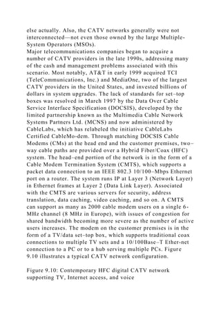
Telephone Network (PSTN) through a modem. Table 9.1
provides a comparison of some of the key DSL options.
Table 9.1: DSL Technology Comparisons
Open table as spreadsheet
DSL Type
ITU Standard
Maximum Rate Downstream[a]
Maximum Rate Upstream[b]
Maximum Reach; Extendable (Yes/No)
Applications
ADSL
G.992.1 (1999)
7 Mbps
800 kbps
18,000 ft (Y)
Consumer-class Internet
G.lite
G.992.2 (1999)
1.544 Mbps
512 Mbps
18,000 ft (Y)
Consumer-class Internet
ADSL2
G.992.3, G.992.4 (2002)
12 Mbps
1 Mbps](https://image.slidesharecdn.com/introductionthisisanindividualproject-221111011410-318fc01d/85/IntroductionThis-is-an-individual-project-Each-student-must-comp-docx-14-320.jpg)
![18,600 ft (N)
Consumer-class Internet
ADSL2+
G.992.5 (2003)
24.5 Mbps
1 Mbps
18,000 ft[c] (N)
Consumer-class, SME Internet
ADSL2-RE
G.992.3 (2003)
8 Mbps
1 Mbps
20,700[d] (N)
Consumer-class Internet
IDSL
N/A
144 kbps
144 kbps
18,000 ft (Y)
Consumer-class Internet
Symmetric HDSL
G.991.2 (2003)
4.6 Mbps
4.6 Mbps
6,000 ft (Y)
Business–class Internet
VDSL
G.993.1 (2004)
55 Mbps
15 Mbps
1,000 ft[e] (N)
Voice, data, video
VDSL2: 12 MHz
G.993.2 (2005)
55 Mbps
30 Mbps](https://image.slidesharecdn.com/introductionthisisanindividualproject-221111011410-318fc01d/85/IntroductionThis-is-an-individual-project-Each-student-must-comp-docx-15-320.jpg)
![1,000 ft[c] (N)
Voice, data, video
VDSL2: 30 MHz
G.993.2 (2005)
100. Mbps
100 Mbps
500 ft[f] (N)
Voice, data, video
[a]Downstream is from the network edge to the customer
premises.
[b]Upstream is from the customer premises to the network edge.
[c]Maximum achievable rates downstream and upstream are
achievable at distances up to 5000 ft. Considerably reduced
rates are achievable at distances up to 18,000 ft.
[d]Maximum achievable rates downstream and upstream are
achievable at distances up to 18,000 ft. Rates up to 192 kbps
downstream and 96 kbps upstream are achievable at distances
up to 20,700 ft.
[e]Maximum achievable rates downstream and upstream are
achievable at distances up to approximately 1000 ft, after which
rates drop precipitously. Considerably reduced rates are
achievable at distances up to 4000-5000 ft.
[f]Maximum achievable rates downstream and upstream are
achievable at distances up to approximately 500 ft, after which
rates drop precipitously. Considerably reduced rates are
achievable at distances up to 4000-5000 ft.
All xDSL technologies are fairly demanding of the local loop.
Some are absolutely unforgiving, and some are adaptive to local
loop anomalies. Before examining the specific technologies, I
want to examine the problems with electrically based local
loops, each of which has definite impact on xDSL performance:
· Loop length has a significant effect on signal strength and,
therefore, on error performance. This is particularly true at high
frequencies, which attenuate much more quickly (i.e., over a
shorter distance) than do low frequencies. Further, attenuation
especially is an issue given the narrow gauge (usually 24 or 26](https://image.slidesharecdn.com/introductionthisisanindividualproject-221111011410-318fc01d/85/IntroductionThis-is-an-individual-project-Each-student-must-comp-docx-16-320.jpg)
![gauge) of voice–grade, twisted–pair outside cable plants. As all
of the xDSL technologies are designed to support relatively
high speed data, they run at relatively high frequencies, at least
in comparison to the 4–kHz range over which analog voice is
supported. Many of the xDSL technologies are designed to work
over local loops as long as 18,000 ft, which describes the vast
majority of ILEC loops. Other xDSL technologies require loop
lengths in the range of 12,000 ft or less due to the higher
frequencies utilized. The reach of some of the technologies can
be extended through the use of loop extenders or line doublers,
which essentially are DSL repeaters. Other DSL types cannot be
extended and performance is highly sensitive to loop length,
with shorter loops offering better performance. Approximately
85 percent of all U.S. residential loops are within 18,000 ft (5.5
km), and approximately 75 percent are within 12,000 ft (3.7 km)
[4]. The same holds roughly true for the United Kingdom [5].
· Splices and mixed gauges can cause echo, or signal reflection,
which is a source of noise, or signal distortion. It is not at all
uncommon to find mixed 24–and 26–gauge cable in a given
local loop. It is not as though the ILEC craftspeople just closed
their eyes and reached into the warehouse for a reel of cable,
but the effect is the same as if they had. Telcordia Technologies
estimates that the average residential local loop involves 22
splices, each of which contributes to the problem [6]. Some of
those splices may not be mechanically sound, and some of the
splice casings may not be well insulated. The problem is likely
to be worse with longer loops, as they generally involve more
splices. Echo cancellers and error detection and correction
algorithms can compensate for much of this noise, but it is
always an issue.
· Bridged taps are sections of a cable pair not on the direct
electrical path between the CO and the customer premises. They
generally are in place because a previous customer between the
CO and the subject building was connected to the CO through
the same pair. When that customer disconnected service, the
splice was not removed. If a telephone is connected, the bridged](https://image.slidesharecdn.com/introductionthisisanindividualproject-221111011410-318fc01d/85/IntroductionThis-is-an-individual-project-Each-student-must-comp-docx-17-320.jpg)
![example, is in a 1909 farmhouse. It's a great place to write a
book, but the inside wiring system is of uncertain nature. My
lovely wife, Margaret, telecommutes in connection with her
consulting practice, so we share the space. We have five lines
coming into our SOHO, and I can't even count the number of
jacks for our analog telephone sets, fax machine, computer
modems (she has to gain access to some client networks on a
dial–up basis), and DSL service. Margaret installed some of the
jacks, so I have to be careful what I put in print, but suffice it to
say that our wiring system is somewhat unusual. In any event,
running high–speed data to our workstations could be an
interesting, and uncertain, experience unless we recabled the
offices. [Note: We recabled the connection from the Network
Interface Unit (NIU) to our ADSL modem with Cat 5, used a
Cat 5 cable to our 802.11b Wireless LAN (WLAN)
bridge/router, used a Cat 5 cable to connect to my desktop, and
went wireless to our three laptops.]
· Voice instrument signaling states can impact data
communications in a DSL environment. While analog voice
circuits are standardized and voice terminals are certified, the
wide variety of devices vary enough in their electrical
characteristics to cause unpredictable problems when
integrating voice and data over a common inside wiring plan.
For that matter, the electrical characteristics of multiple phones
of the same manufacturer and model number can vary
considerably, even within the same manufacturing lot. DSL data
communications sessions can be dropped when analog
telephones ring (voltages can exceed 100 V), when they go off–
hook, and when they go back on–hook. The ultimate solution is
an adaptive splitter or modem. The interim solution, at least for
some versions of DSL, involves equipping all telephone sets,
fax machines, and other connected devices with inexpensive
high–pass microfilters that plug in between the set and the jack.
· Digital Loop Carrier (DLC) systems are voice–grade
multiplexers embedded in a local loop distribution plant to
increase its efficiency. Subscriber Line Carrier (SLC) 96, for](https://image.slidesharecdn.com/introductionthisisanindividualproject-221111011410-318fc01d/85/IntroductionThis-is-an-individual-project-Each-student-must-comp-docx-20-320.jpg)
![ADSL, IDSL, G.lite, and VDSL. The technologies discussed last
are those intended primarily for the larger business market:
HDSL, HDSL2, SDSL, and SHDSL.
9.1.1.1 Asymmetric Digital Subscriber Line
Asymmetric Digital Subscriber Line (ADSL), also known as
full-rate ADSL, is an advanced, high-bandwidth local loop
technology designed to extend the life of existing UTP loops for
the transmission of broadband signals. ADSL was developed by
Bellcore (now Telcordia Technologies) at the request of the
RBOCs in the United States and was later standardized in 1999
by ANSI as T1.413 and the ITU–T as G.922.1. ADSL provides
for very high capacity transmission over relatively short local
loops in the Carrier Serving Area (CSA). The DSL Forum, a
Special Interest Group (SIG) dedicated to the promotion of
xDSL technologies, promotes this technology [7].
The term asymmetric refers to the fact that ADSL bandwidth is
provided on an asymmetric (i.e., not symmetric, or unequal)
basis, with more bandwidth in the downstream direction than in
the upstream direction. This asymmetry is in recognition of the
FEXT and NEXT crosstalk issues discussed above and generally
suits the applications.
In addition to supporting POTS voice over a separate analog
channel running at 4 kHz and below, ADSL supports high–speed
data. The upstream data ride in what technically is a
bidirectional channel provided in increments of 64 kbps up to
640 kbps in a frequency band from 26 to 140 kHz. Downstream
transmission is in increments of 1.536 Mbps up to 6.144 Mbps,
based on T1 specifications, in a frequency band that runs from
approximately 140–552 kHz. While ADSL is primarily a Layer
1 (Physical Layer) specification, it includes Layer 2 (Data Link
Layer) elements. ADSL specifies three modes of operation:
· Synchronous Transfer Mode (STM), which is a bit
synchronous mode. In this mode, the ADSL loop is a bit pipe.
· Asynchronous Transfer Mode (ATM).
· Packet Mode is IP–centric, employing both Ethernet and a
variation of the High–level Data Link Control (HDLC) framing](https://image.slidesharecdn.com/introductionthisisanindividualproject-221111011410-318fc01d/85/IntroductionThis-is-an-individual-project-Each-student-must-comp-docx-24-320.jpg)
![requirements for e-mail, Internet access, and remote LAN
access are satisfied. Once the cable plant is deemed acceptable,
a splitter must be installed at the customer premises , and the
circuit must be tested in order to meet the very tight tolerances.
The local loop demands and the installation of a splitter require
an ILEC truck roll, which makes the provisioning process fairly
labor intensive and, therefore, expensive [8].
Table 9.2: ADSL Data Rates, Wire Gauges, and Distance
Limitations
Open table as spreadsheet
Data Rate
American Wire Gauge (AWG)
Distance (ft)
Metric Gauge (mm)
Distance (km)
1.544/2.048 Mbps
24
18,000
0.5
5.5
1.544/2.048 Mbps
26
15,000
0.4
4.6
6.1 Mbps
24
12,000
0.5
3.7
6.1 Mbps
26
9,000
0.4
2.7
Source: DSL Forum.](https://image.slidesharecdn.com/introductionthisisanindividualproject-221111011410-318fc01d/85/IntroductionThis-is-an-individual-project-Each-student-must-comp-docx-28-320.jpg)
![out the noise from Amplitude Modulation (AM) radio
interference and, thereby, to realize improved coding gain.
ADSL2 systems feature reduced framing overhead, enhanced
power management, faster startup, seamless rate adaption, and
improved diagnostics. ADSL2 also features an all–digital mode,
in which the analog voice channel can be used for digital data
transmission, thereby increasing aggregate upstream data
transmission rates by as much as 256 kbps. ADSL2 adds a
packet-mode capability that enables packet–based services such
as Ethernet. On long loops, ADSL2 can increase the data rate by
as much as 50 kbps and extend the reach by about 600 ft (200
m).
ADSL2 supports bonding in ATM, based on the ATM Forum
specification for Inverse Multiplexing over ATM (IMA). This
allows two ADSL pairs to be bonded together to yield roughly
double the single–pair rate across the full range of loop lengths.
Bonding has increasing application, as competition from CATV
providers and cellular services have led to the disconnection of
large numbers of telco-provided copper landlines. The
deployment of pair gain technologies such as ADSL and the
increasing use of fiber optics have combined to further reduce
the pair counts required to support primary and secondary lines
and trunks and have added to the excess of available copper
loops.
ADSL2 further supports channelization, which provides the
ability to split the bandwidth into different channels with
different link characteristics in support of different
applications. For example, a single ADSL2 loop might support a
business class videoconferencing application, which is
intolerant of both latency and bit errors, while simultaneously
supporting e-mail transfers, which are quite tolerant of both
latency and bit errors. Channelized Voice over DSL (CVoDSL)
allows multiple derived lines of TDM voice traffic to be
transported simultaneously over DSL in 64-kbps channels [9].
9.1.1.1.2 ADSL2+
The ITU–T reached agreement on G.992.5 in January 2003,](https://image.slidesharecdn.com/introductionthisisanindividualproject-221111011410-318fc01d/85/IntroductionThis-is-an-individual-project-Each-student-must-comp-docx-30-320.jpg)
![adding ADSL2 + to the ADSL suite. This specification doubles
the downstream data rate to as much as 24.5 Mbps over shorter
loops up to approximately 5000 ft (1500 m) in length. The
upstream rate remains at a maximum of 1 Mbps. In order to
achieve this enhanced data rate, ADSL2+ increases the
downstream frequency range from 552 kHz (ADSL) and 1.1
MHz (ADSL2) to 2.2 MHz (ADSL2+) and increases the number
of subcarriers to 512. The analog POTS channel remains at 4
kHz (ADSL and ADSL2), and the upstream data channel
remains capped at 140 kHz (ADSL2). Table 9.3 provides a
quick comparison of the frequency ranges of the various ADSL
technologies.
Table 9.3: ADSL Frequency Ranges
Open table as spreadsheet
Channel/ADSL Version
ADSL
ADSL2
ADSL2+
Downstream data
138-552 kHz
138 kHz-1.1 MHz
138 kHz-2.2 MHz
Upstream data
25–138 kHz
25–138 kHz
25–138 kHz
Voice
0-4 kHz
0-4 kHz
0-4 kHz
ADSL2+ also can be used to reduce crosstalk by using only the
frequencies between 1.1 and 2.2 MHz and masking those below
1.1 MHz. This can be useful when ADSL signals from a CO and
a remote terminal are present in the same 25–pair binder group
in a cable [9].
Recent developments in ADSL+ CPE support multiple 10/100](https://image.slidesharecdn.com/introductionthisisanindividualproject-221111011410-318fc01d/85/IntroductionThis-is-an-individual-project-Each-student-must-comp-docx-31-320.jpg)
![Mbps Ethernet interfaces and optional 802.11 b/g interfaces.
Combining these enhancements with the increased bandwidth of
ADSL2+ and its channelization capability allows the user
organization to derive multiple VLANs from a single ADSL2+
facility, with each VLAN enjoying its own Quality–of–Service
(QoS) level. Thereby, separate VLANs can be created for low–
latency voice and video as well as latency–tolerant data
communications applications in a triple–play scenario. ADSL2
and ADSL2+ certainly relieve the pressure on triple–play
bandwidth. MPEG–2 compression reduces the Standard
TeleVision (STV) requirement to 3.5 Mbps and that of High-
Definition TV (HDTV) to 8.0 Mbps, all of which is
downstream, of course. PCM-based voice requires bidirectional
bandwidth of only 64 kbps, which leaves plenty of room for
high–speed bidirectional data [10].
9.1.1.2 G.lite
Also known as ADSL Lite, Universal ADSL, and Splitterless
ADSL, G.lite is an interoperable extension of the ADSL
specification ANSI T1.413 and has been standardized by the
ITU–T as G.992.2. Three deployment options exist, all of which
support simultaneous voice and data communications over a
single UTP local loop of one physical pair:
· Splittered ADSL resembles the original standardized version
of ADSL, in that a single, professionally installed splitter is
installed at the point of termination of the local loop at the
customer premises. This approach ensures the highest level of
data performance, while ensuring that other signals in a
multipair cable are not affected by high–frequency ADSL data
signals. But this approach also involves an expensive truck roll.
· Distributed Splitter ADSL involves a number of ADSL
splitters, some front-ending PCs and others front–ending analog
telephone sets. This approach ensures that the voice and data
channels do not interfere with each other and avoids the costs
and delays associated with the professional installation of a
single splitter, as described in the Splittered ADSL option. This
version does not require professional installation.](https://image.slidesharecdn.com/introductionthisisanindividualproject-221111011410-318fc01d/85/IntroductionThis-is-an-individual-project-Each-student-must-comp-docx-32-320.jpg)
![· Splitterless ADSL (see Figure 9.5), which is the most
attractive, supports simultaneous voice and data without the
requirement for either a centralized splitter or multiple
distributed splitters. Rather, high–frequency data
communications are supported over an ADSL modem. This
version does not require professional installation.
Figure 9.5: Splitterless G.lite
G.lite operates on an asymmetric basis over loops up to 18,000
ft at speeds of up to 1.544 Mbps (T1) downstream and up to 512
kbps upstream, sensitive to loop specifics such as gauge.
Upstream and downstream speeds both are selectable in
increments of 32 kbps. Shared internal wiring is always an issue
but generally is resolved satisfactorily with microfilters
installed between the jacks and the analog voice sets and fax
machines. The filters prevent the analog devices from draining
the high–frequency signal power, thereby improving the signal–
to–noise ratio for the modem. Maximum performance can be
achieved by upgrading the internal wire to Cat 5, at least for the
PC connection, and by home–run cabling the jacks to the NIU
[11–13]. (Note: This is basically the approach we took at The
Context Corporation, and it worked beautifully. With the
exception of one desktop computer, however, all computers
were interconnected to the G.lite circuit through an 802.11b
WLAN.)
G.lite supports both voice and data over the same circuit, just as
does full–rate ADSL, but G.lite uses several mechanisms to
optimize their coexistence. Power back-off dynamically reduces
the modem power level at the customer premises in order to
eliminate the potential for interference (NEXT) with the analog
voice channel. Power back–off occurs automatically and reduces
the upstream data transmission rate for the duration of the
phone call. Fast retrain enables rapid recovery of the upstream
when the phone call is terminated. Fast retrain supports the
retention in memory of profiles for as many as 16 telephone
sets, thereby taking into consideration the specific electrical](https://image.slidesharecdn.com/introductionthisisanindividualproject-221111011410-318fc01d/85/IntroductionThis-is-an-individual-project-Each-student-must-comp-docx-33-320.jpg)
![attributes associated with each. Although early G.lite modems
ran Frame Relay as the Layer 2 protocol, contemporary modems
mostly run ATM [14]. As G.lite is limited in terms of
bandwidth, it never achieved great popularity but did introduce
the concept of Splitterless DSL.
9.1.1.3 ISDN Digital Subscriber Line
ISDN DSL uses ISDN BRI (Basic Rate Interface) technology to
deliver symmetrical transmission speeds of 128 or 144 kbps on
digital copper loops as long as 18,000 ft. Like ISDN BRI
(Chapter 7), IDSL terminates at the user premises on a standard
ISDN Terminal Adapter (TA). At this point, the two concepts
diverge. ISDN is a circuit–switched service that connects to a
CO at the edge of the carrier domain. IDSL is an always–on
data access service that terminates, more or less directly, in a
DSLAM. ISDN supports voice, data, video, and any other form
of traffic through one or more Bearer (B) channels, each with a
width of 64 kbps. ISDN also can support X.25 packet data over
a Delta (D) channel at speeds of up to 9.6 kbps. IDSL supports
data access through a contiguous slice of bandwidth with a
width 128 or 144 kbps. ISDN can support multiple
transmissions, each over a separate channel. IDSL supports a
single data transmission at a time over a single, wider channel.
IDSL (refer to Figure 9.6) is a dedicated access service for data
communications applications, only. At the Local Exchange
Carrier (LEC) CO, the loop terminates in collocated electronics
in the form of either an IDSL access switch or an IDSL modem
bank connected to a router or DSLAM. In the event that the
LEC is not serving as the ISP, the connection is made to the
third–party ISP POP via a high–bandwidth dedicated circuit,
such as unchannelized T1, T3, or SONET/SDH channel.
Figure 9.6: ISDN DSL configuration
IDSL offers several advantages over competing technologies.
IDSL is based on ISDN network technologies, which are
standardized, well understood, and widely implemented, at least
outside the United States. IDSL operates at frequencies that do](https://image.slidesharecdn.com/introductionthisisanindividualproject-221111011410-318fc01d/85/IntroductionThis-is-an-individual-project-Each-student-must-comp-docx-34-320.jpg)
![12-28 MHz
Upstream/downstream optional
8.5-12.0 MHz
Upstream
5.2-8.5 MHz
Downstream
3.75-5.2 MHz
Upstream
138 kHz-3.75 MHz
Downstream
25-138 kHz
Upstream
0 Hz-4 kHz
Analog voice
There are several application scenarios, all of which are based
on FTTN hybrid local loops, with fiber optics from the CO to
the neighborhood ngDLC and VDSL to the premises. In North
America, Europe, and China, there are plans to deploy VDSL2
at downstream rates up to 30 Mbps and upstream rates of 3
Mbps in support of consumer–class triple–play services,
including at least three Digital TV (DTV) or HDTV channels,
Internet access at rates up to 5 Mbps, and VoIP. Clearly VDSL
has application in servicing a MultiDwelling Unit (MDU), also
known as a MultiTenant Unit (MTU), where the bandwidth can
be shared among multiple tenants. In this Fiber-To-The-
Premises (FTTP) scenario, the ngDLC is positioned on the
premises, and the VDSL service runs over the inside wire and
cable system in the apartment building or office building, for
example [15].
As VDSL matures and implementations become more prevalent,
the pressure increases to increase the bandwidth levels and
speed ratings, to alter the bandplan toward symmetrical service,
and to increase the distances. In combination, these demands
will outstrip the capabilities of the specification. As a result,
there has been some movement toward the application of
Multiple-Input, Multiple-Output (MIMO) technology similar to](https://image.slidesharecdn.com/introductionthisisanindividualproject-221111011410-318fc01d/85/IntroductionThis-is-an-individual-project-Each-student-must-comp-docx-37-320.jpg)
![that used in 802.11 Wireless Local Area Networks (WLANs). In
a VDSL application, MIMO treats each binder group of 25 pairs
as a MIMO channel and the transceiver treats multiple pairs
together, thereby separating signal from crosstalk [16].
According to the DSL Forum, some manufacturers have
included MIMO in VDSL2 systems in advance of
standardization of MIMO technology.
9.1.1.5 High–Bit–Rate Digital Subscriber Line
Bellcore (now Telecordia Technologies) also developed High
Bit–Rate Digital Subscriber Line (HDSL) at the request of the
RBOCs as a more cost–effective means of providing T1 local
loop circuits over existing UTP. Standardized by the ANSI
T1E–1.4 committee, HDSL eliminates repeaters in the T1 local
loop for distances up to 12,000 ft, which can be extended
another 12,000 ft through the use of a line doubler, which
essentially is an HDSL repeater.
Recall from Chapter 7 that conventional T1 uses two pairs, each
of which operates in a simplex mode (one upstream and one
downstream) at the full T1 transmission rate of 1.544 Mbps (see
Figure 9.7). The line coding technique for T1 is Alternate Mark
Inversion (AMI), which yields 1.544 Mbps at a nominal carrier
frequency of 784 kHz, which is exactly half the T1 bit rate, plus
some overhead for error control. At such a high frequency,
issues of attenuation are significant. As a result, it is necessary
that repeaters be spaced at approximately 6000 ft to adjust for
distortion and signal loss. Also, the radiated electromagnetic
field is significant at T1 frequencies. Therefore, interference
between the T1 pairs and other pairs in the cable system is an
issue. Also recall that E–1 uses AMI as well, in support of the
E–1 transmission rate of 2.048 Mbps at a frequency of 1.168
MHz, which also is half the bit rate, plus some additional
overhead.
Figure 9.7: Comparison of T1 and HDSL
In the North American implementation of HDSL, the upstream
and downstream signals are split across both pairs, with each](https://image.slidesharecdn.com/introductionthisisanindividualproject-221111011410-318fc01d/85/IntroductionThis-is-an-individual-project-Each-student-must-comp-docx-38-320.jpg)
![incremental cost is mitigated to some extent. Additionally, the
cable plant supporting HDSL does not require special
conditioning or engineering, further reducing costs, as well as
enabling service to be provisioned much more quickly. Finally,
HDSL offers error performance of approximately 10 -10, as
compared to the 10 -7 level offered by repeatered T1 over
twisted pair [17]. The bottom line is that T1 network access can
be provisioned much more quickly and much less expensively
with HDSL and with improved error performance as compared
to traditional T1 or E–1. The carriers, therefore, realize
revenues more quickly and at such reduced costs that many pass
on those cost savings to end users in the form of lower
installation charges and reduced monthly rates for the service.
Since its introduction in 1992, the vast majority of T1 and E–1
circuits installed have been HDSL loops.
HDSL2 is an HDSL variant that supports T1 speeds of 1.544
Mbps over a single twisted pair (two conductors) and over 24
AWG loops up to 13.2 kft, 768 kbps at up to 17.7 kft, and 384
kbps at up to 22.5 kft. The international E–1 version supports
signaling speeds up to 2.3 Mbps. An HDSL2 regenerator can
double the distance for each speed rating. A variation known as
HDSL4 can run over two copper loops (four physical
conductors) in order to extend the maximum transmission span
to as much as 16,500 ft. HDSL2's level of performance is
achieved through an advanced coding technique known as
Trellis-Coded Pulse Amplitude Modulation (TC-PAM). This
technique places three bits on a baud, which is an improvement
over the two bits per baud realized through the 2B1Q technique
used in HDSL. While the bandwidth required to support the
HDSL signal is sensitive to the implementation, TCM features
inherent Forward Error Correction (FEC) to overcome line
impairments and issues of Signal–to–Noise Ratio (SNR),
thereby offering excellent performance and the same reach as
HDSL but requiring only a single pair. With respect to
applications, HDSL is essentially a Layer 1 bit pipe that
replaces leased full–rate and fractional T1 and E–1 local loops](https://image.slidesharecdn.com/introductionthisisanindividualproject-221111011410-318fc01d/85/IntroductionThis-is-an-individual-project-Each-student-must-comp-docx-40-320.jpg)
![in support of any bit stream, including TDM voice, ATM, and
Frame Relay, for example. Although the standard version does
not support telephone service over the same line, some
equipment manufacturers offer a passive POTS splitter [18].
9.1.1.6 Symmetric Digital Subscriber Line
Symmetric DSL (SDSL), also known as Single-line DSL, is an
umbrella term for nonstandard variations on the HDSL theme
running over a single pair. SDSL uses the same 2B1Q line
coding as HDSL and runs at rates from 128 kbps to 2.32 Mbps.
Example speeds are 384 kbps for loop lengths of up to 18,000 ft
and 768 kbps for loop lengths of up to 12,000 ft (see Figure
9.8). Providers generally limit SDSL to transmission rates of
768 kbps, which is half the payload of a full T1. At that data
rate, the signaling rate is 784 kbps, including 16 kbps of error
control overhead. At a data rate of 384 kbps, which is one–
fourth a full T1, the signaling rate is 400 kbps.
Figure 9.8: Symmetric DSL
9.1.1.7 Symmetric High–Bit–Rate Digital Subscriber Line
Symmetric HDSL (SHDSL), also known as G.shdsl, is a
business class DSL technology ratified by the ITU–T in
February 2001 as G.991.2. SHDSL supports symmetric rate–
adaptive transmission ranging from 192 kbps at 20,000 ft (6 km)
to 2.312 Mbps at 10,000 ft (3 km) in increments of 8 kbps over
a single pair, sensitive to loop specifics. An optional two–pair
(four–wire) mode supports data rates ranging from 384 kbps to
4.624 Mbps in increments of 16 kbps. At the two–pair mode and
at a rate of 2.312 Mbps, the SHDSL reach is targeted at 16,000
ft (5 km). In either mode, repeaters can double the distance.
SHDSL uses the same Trellis-Coded Pulse Amplitude
Modulation (TC-PAM) advanced coding technology as HDSL2
and HDSL4. SHDSL operates in a rate–adaptive mode as well as
a fixed–rate mode at 784 kbps and 1.544 Mbps.
SHDSL can transport T1, E–1, ISDN, ATM, and IP signals, with
the specific framing requirements negotiated during the
handshaking process defined in G.994.1. Although SHDSL is](https://image.slidesharecdn.com/introductionthisisanindividualproject-221111011410-318fc01d/85/IntroductionThis-is-an-individual-project-Each-student-must-comp-docx-41-320.jpg)
![intended for data–only applications, newer techniques will
support voice as well [19–21]. Targeted applications include
Web hosting, videoconferencing, Virtual Private Network
(VPN) services, and remote LAN access. Note: SHDSL is
specified for North America in ANSI T1E–1.4/2001–174, for
Europe in ETSI TS 101524, and worldwide in ITU–T G.991.2.
9.1.1.8 Voice over DSL
Voice over DSL (VoDSL) refers to a nonstandard technique for
supporting voice over various business–class DSL technologies.
Spe-cifically, VoDSL runs over SDSL and SHDSL, with ATM
as the layer 2 protocol. At the customer premises in a VoDSL
implementation, both voice and data connect through a
centralized Integrated Access Device (IAD). The IAD serves, as
necessary, to convert the analog voice into G.711 PCM samples
through a codec embedded in a Digital Signal Processor (DSP)
contained within the IAD. The DSP then generally compresses
the voice streams by using one of a number of available
compression algorithms, with G.726 Adaptive Differential Pulse
Code Modulation (ADPCM) being widely used for this purpose.
The IAD then forms the uncompressed voice samples into ATM
cells using ATM Adaptation Layer 1 (AAL1), or the compressed
voice samples using AAL2, with the voice cells prioritized over
the AAL3/4 data cells in either case. VoDSL also can be
supported on an uncompressed G.711 PCM basis through AAL1.
(Note: ATM and AALs are discussed in detail in Chapter 10.)
At the service provider's CO or other Point Of Presence (POP),
the ATM-based DSLAM demultiplexes the cells, routing the
voice and data streams as appropriate, extracting them from the
ATM cell format as appropriate. While the specifics vary by
vendor, VoDSL commonly supports 4, 8, 12, or 16 voice
conversations over a circuit, depending on the line rate and the
compression algorithm employed. Some support as many as 40
voice conversations over full–rate (i.e., 1.544–Mbps) DSL, but
there always is an upper limit. VoDSL reserves the remaining
bandwidth in support of data communications, thereby ensuring
some level of bandwidth is available for both voice and data.](https://image.slidesharecdn.com/introductionthisisanindividualproject-221111011410-318fc01d/85/IntroductionThis-is-an-individual-project-Each-student-must-comp-docx-42-320.jpg)
![Should there be fewer than the maximum number of voice
conversations active at any given moment, data can lay claim to
that available bandwidth as long as it is available. This dynamic
bandwidth allocation serves to optimize the use of the DSL
circuit at all times [22–27].
9.1.2 Community Antenna Television
Cable television, formally known as Community Antenna
TeleVision (CATV), was born in the mountains in the state of
Pennsylvania in the United States. In the late 1940s, there were
only a few TV stations, all located in major cities. As TV
transmit and receive antennas operated exclusively over the air,
signal quality was sensitive to Line–of–Sight (LOS),
ElectroMagnetic Interference (EMI) and Radio Frequency
Interference (RFI), weather conditions, and other factors.
Reception was poor, even in the cities, and awful elsewhere. In
remote rural areas and particularly in mountainous areas where
LOS was not possible, reception was next to impossible, even
on the best of days. John and Margaret Walson, owners of the
Service Electric Company, a retail appliance store in Mahanoy
City, were having a difficult time selling TV sets as reception
was so poor in the valley where the town was situated, 90 miles
from Philadelphia. In order to demonstrate TV sets to their best
advantage, Mr. Walson placed an antenna on top of a tall utility
pole on a nearby mountaintop and ran antenna wire to the store.
In June 1948, he built some amplifiers to bring the signal to
customers who had bought his TV sets, thereby creating the first
CATV network. Walson also was the first to use microwave to
import TV signals from distant stations and the first to use
coaxial cable to improve reception. In 1972, Walson also was
the first to distribute Home Box Office (HBO), which marked
the beginning of pay TV and the start of the explosive growth of
the CATV industry [28, 29].
Until very recently, all CATV systems were analog in nature,
and many remain so. The community antenna actually consists
of multiple satellite and microwave antennas located at a head
end, which is the point of signal origin for the CATV network.](https://image.slidesharecdn.com/introductionthisisanindividualproject-221111011410-318fc01d/85/IntroductionThis-is-an-individual-project-Each-student-must-comp-docx-43-320.jpg)
![At the head end, multiple analog TV broadcast signals are
interwoven through a frequency division multiplexer and carried
over a coaxial cable system to the community or neighborhood
to be served. In the United States, each 6-MHz video channel
carries a signal in the National Television Standards Committee
(NTSC) format. [Note: In European and many other countries,
the Phase Alternate Line (PAL) format requires an 8-MHz
channel.] Within each 6-MHz channel, approximately 250 kHz
is transition bands, or guard bands, 4.2 MHz is required for the
video, another 300 kHz is required for the audio signal, and the
balance is due to the Vestigial SideBand Amplitude Modulation
(VSB-AM) technique utilized as the signal is placed on the
Radio Frequency (RF) carrier. Contemporary coax–based CATV
systems commonly support aggregate raw bandwidth of 500–850
MHz, thereby supporting a great number of TV channels, all of
which reside on the system simultaneously. CATV networks
conform to a tree-and-branch architecture comprising a trunk
system, a distribution system, and hundreds or perhaps
thousands of subscriber drops, as illustrated in Figure 9.9. At
each subscriber premises, the coax cable drops terminate in
converter boxes, or set-top boxes, which serve as frequency
division demultiplexers. As each individual channel is selected,
the set–top box selects the appropriate frequency range.
Traditionally, these networks have been analog, coax–based,
one–way networks for the downstream delivery of analog
entertainment TV. Few changes occurred in CATV networks
until the 1990s.
Figure 9.9: Traditional analog CATV network, with tree-and-
branch architecture
Beginning in the mid–1990s, a few large CATV providers began
to upgrade their aging coaxial cable systems. As many of those
networks were installed in the late 1960s and early 1970s, they
were in awful shape. Further, those networks were strained for
capacity as the CATV providers sought to increase revenues and
profits through the introduction of premium movie channels and](https://image.slidesharecdn.com/introductionthisisanindividualproject-221111011410-318fc01d/85/IntroductionThis-is-an-individual-project-Each-student-must-comp-docx-44-320.jpg)
![DOCSIS is both always on and generally asymmetric in nature,
as are most xDSL technologies. DOCSIS 2.0 specifications
address downstream and upstream channels:
· Downstream: The head end broadcasts downstream
transmissions to all premises on the shared point–to–multipoint
network. DOCSIS modems carve a downstream channel from
the coax cable in the form of one or more 6-MHz channels in
the range between 50 and 750–850 MHz, with the exact range
being system dependent. DOCSIS 2.0, the current version,
specifies 64-point Quadrature Amplitude Modulation (64-QAM)
for the downstream channels, yielding six bits per symbol and
yielding a potential of 36 Mbps per 6-MHz channel. (See Table
9.5.) Overhead for framing and Forward Error Correction (FEC)
reduces that level to approximately 27–31 Mbps of shared
bandwidth per 6-MHz channel. Alternatively, 128-QAM yields
seven bits per symbol, respectively, and the signaling speed to
42 Mbps, although it is more sensitive to noise. The standards
also provide for the use of 256-QAM, which increases the raw
signaling speed to 48 Mbps. These variations on QAM are
compatible with Moving Picture Experts Group–2 (MPEG–2),
the compression technique specified for digital video
transmission in CATV networks. Downstream data are
encapsulated into MPEG–2 packets of 188 bytes.
Table 9.5: DOCSIS Physical Layer
Open table as spreadsheet
FDMA+[a]
Channel Width (MHz)
Modulation
Bits/Symbol
Symbol Rate (Msps)
Signaling Speed (Mbps)
Downstream](https://image.slidesharecdn.com/introductionthisisanindividualproject-221111011410-318fc01d/85/IntroductionThis-is-an-individual-project-Each-student-must-comp-docx-47-320.jpg)
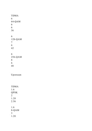
![3.84
3.2
16-QAM
4
2.56
10.24
3.2
32-QAM
5
2.56
12.8
6.4
64-QAM
6
5.12
30.72
S-CDMA
6.4
128-QAM TCM
7[b]
5.12
30.72
[a]Frequency Division Multiple Access.
[b]Six bits payload, 1 bit error control.
· Upstream: In early versions of DOCSIS, transmissions
upstream from the user premises to the head end are supported
either through the contentious CSMA/ CD access protocol used
in Ethernet LANs or through Time Division Multiple Access
(TDMA), depending on the specifics of the CATV provider's
implementation [30, 31]. According to DOCSIS 1.0 standards,
traffic in the upstream direction is supported over 6-MHz
channels in the range between 5 and 42 MHz for U.S. systems
and 8-MHz channels in the range between 5 and 65 MHz for](https://image.slidesharecdn.com/introductionthisisanindividualproject-221111011410-318fc01d/85/IntroductionThis-is-an-individual-project-Each-student-must-comp-docx-49-320.jpg)
![European systems, each of which can operate at about 12 Mbps
through use of the Quadrature Phase Shift Keying (QPSK)
modulation technique. Again, framing and FEC overhead reduce
the level of usable bandwidth, in this case to about 10 Mbps
[32–35]. In a field implementation, many systems use QPSK
across a 1.6-MHz channel, yielding 2.56 Mbps (2 bits per
symbol × 1.28 megasym-bols per second). DOCSIS 1.1 added
16-QAM to the mix, roughly doubling the data rate and
doubling the channel width to 3.2 MHz to double it yet again (4
bits per symbol × 2.56 megasymbols per second), for a four fold
increase to over 10 Mbps. QAM increases sensitivity to noise,
but DOCSIS deals with that through sophisticated noise
cancellation techniques. DOSCIS 2.0 triples the upstream rate
of DOCSIS 1.1 over a channel of 6.4 MHz using either TDMA
in combination with 64-QAM or Synchronous Code Division
Multiple Access (S–CDMA) in combination with 128-QAM
Trellis-Coded Modulation (TCM). S–CDMA transmits 128
orthogonal codes simultaneously (i.e., in the same time slot)
[36].
There also are telco-return modems that use the circuit–
switched PSTN for the upstream path, although this approach
generally proves less than totally satisfactory. Not only does the
telco–return approach require the use of a telco–provided local
loop, which adds costs to the equation, but it slows the upstream
path to modem speeds. Also, the widely mismatched speeds on
the upstream and downstream paths cause the downstream
server to slow down, therefore running at less than optimum
efficiency. DOCSIS 3.0 standards currently under development
are expected to increase upstream data rates to 120 Mbps and
downstream rates to 160 Mbps.
CATV networks also support voice in several possible ways.
The most common approach at this time is the very same TDM
and PCM approach used in the circuit-switched PSTN, although
some CATV networks use ADPCM modulation with silence
suppression. At a rate of roughly one bit per hertz, a 6-MHz
channel supports a considerable number of PCM–based voice](https://image.slidesharecdn.com/introductionthisisanindividualproject-221111011410-318fc01d/85/IntroductionThis-is-an-individual-project-Each-student-must-comp-docx-50-320.jpg)
![channels. (Refer to Chapter 7 for detailed discussions of TDM,
PCM, ADPCM, and silence suppression.) The current focus is
on VoIP, with protocol conversion from VoIP encoding to PCM
encoding occurring at a gateway located at the CATV provider's
head end. The ultimate goal is that of end–to–end VoIP, with
the CATV provider connecting voice directly from the CMTS to
a VoIP backbone. The first approach of TDM–based voice
involves separate voice channels, both upstream and
downstream. VoIP rides over the shared packet data channels,
with the CMTS and cable modems providing priority access in
order to support the QoS demanded for toll–quality voice
communications. Cable telephony requires local power, unlike
traditional telco telephony. In the event that the lights go out,
local battery backup provides telephony support for a few hours
[37, 38], which is especially important in support of calls to
emergency services (e.g., 911). Various estimates indicate that
cable operators in the United States and Canada had signed up
approximately 3.2 million VoIP subscribers as of the end of
2005 and that the rate of growth is about 250,000 per month.
Including the TDM voice customers, cable operators boasted
total voice subscribers numbering about six million [39].
DOCSIS 1.1 provided a number of enhancements, in addition to
QoS support. Fragmentation allows large Ethernet frames to be
fragmented, which naturally improves voice latency. Rather
than having to wait in a buffer until a large Ethernet data frame
can be fully transmitted, the VoIP packet (once framed) can
transit the network after a smaller Ethernet fragment has
completed its journey. Payload header suppression can serve to
reduce overhead, which is especially important for VoIP
packets. Concatenation is a mechanism that links together
multiple packets, which then can be processed as a single entity
in a supperrate service context. Concatenation speeds
processing, which reduces overall network latency. Dynamic
channel allocation allows the CMTS to accomplish dynamically
load balancing, shifting traffic flows between channels in order
to reduce overall network congestion levels. Security is added](https://image.slidesharecdn.com/introductionthisisanindividualproject-221111011410-318fc01d/85/IntroductionThis-is-an-individual-project-Each-student-must-comp-docx-51-320.jpg)
![in the form of authentication, and support for Simple Network
Management Protocol version 3 (SNMPv3) adds network
management capabilities.
The CATV networks remain troubled by several inherent
limitations. First, CATV networks are consumer oriented,
primarily serving residential neighborhoods and not extending
to most businesses. (After all, you are supposed to work at
work, not watch TV.) Second, CATV networks are multipoint
bus networks, much like a classic Ethernet 10Base5 LAN
(Chapter 8). Since your voice and data transmissions pass every
other house connected to the coax cable, security is a major
concern in the absence of an effective encryption mechanism.
Third, much like 10Base5 Ethernet and very much unlike DSL,
the CATV local loop network is shared. Therefore, the more
active users are on the network, the worse the performance.
While the CATV providers speak of total bandwidth of as much
as 500 Mbps and user access at rates of as much as 10 Mbps,
those are best case figures quoted on the assumption that the
load on the shared medium is light enough to support
transmission rates of 10 Mbps for all active users. DOCSIS
cable modems work on an asymmetric basis, as do most xDSL
options. Specifically, the maximum aggregate usable bandwidth
of a downstream channel currently is 31 Mbps, and the
maximum aggregate usable upstream bandwidth ranges from
200 kbps to 10.0 Mbps, depending on the specifics of the field
implementation of a network conforming to DOCSIS 1.1
specifications.
Especially with the strength of AT&T (i.e., AT&T prior to the
merger with SBC) behind it, it seemed as though CATV network
providers had an excellent chance of securing a large segment
of the market for high–speed Internet access. The CATV
providers did, indeed, enjoy considerable success, although
financial problems caused AT&T Broadband to merge with
(read be acquired by) Comcast in 2001, only two years after it
was formed. About the same time, AT&T's primary ISP, At
Home Corp., ceased operations, and its [email protected]](https://image.slidesharecdn.com/introductionthisisanindividualproject-221111011410-318fc01d/85/IntroductionThis-is-an-individual-project-Each-student-must-comp-docx-52-320.jpg)
![asymmetric configurations. Individual subscribers in office
complexes or Multi–Dwelling Units (MDUs) can gain access to
bandwidth in increments of 64 kbps (DS–0). Multiplexing
access methods include Frequency Division Multiple Access
(FDMA), Time Division Multiple Access (TDMA), and Code
Division Multiple Access (CDMA). TDMA modulation options
include Phase Modulation (BPSK, DQPSK, QPSK, and 8PSK)
and Amplitude Modulation (QAM, 16–QAM, and 64–QAM).
As noted above, LMDS generated a lot of excitement in 1998
and again in the 1999–2000 time frame, and hundreds of
millions of dollars were spent securing LMDS licenses at
spectrum auctions in the United States. Most of the successful
bidders (e.g., Teligent, WinStar, and Advanced Ratio Telecom)
have since declared bankruptcy. XO Communications
(previously Nextlink) invested a total of approximately $ 900
million in those licenses and now holds licenses in 73 major
cities in the United States. XO installed a small number of
systems over the intervening years but never was able to
achieve any real success with LMDS due to technological
problems and high equipment costs. In early 2006, however, XO
announced a new LMDS initiative targeted at cellular backhaul
as well as enterprises and government agencies looking for
access alternatives, redundancy, and disaster recovery solutions
[40–42]. [Note: In this context, backhaul refers to the
transporting of traffic between distributed sites, such as cellular
base stations, and a backbone or centralized network or site,
such as a Mobile Traffic Switching Office (MTSO), or other
point of concentration or switching.] Most of the current
interest in WLL is on IEEE 802.16, aka WiMAX, which I
discuss later in this chapter.
9.1.3.2 Multichannel Multipoint Distribution Service
Operating in five bands in the range 2.15–2.68 GHz in the
United States and Canada and in the 3.5-GHz range elsewhere,
Multichannel Multipoint Distribution Service (MMDS), also
known as wireless cable, initially was developed for one–way
TV transmission. As the name suggests, MMDS is a point–to–](https://image.slidesharecdn.com/introductionthisisanindividualproject-221111011410-318fc01d/85/IntroductionThis-is-an-individual-project-Each-student-must-comp-docx-56-320.jpg)
![multipoint technology that operates from an antenna typically
placed on a hilltop or other location in order to maximize Line–
Of–Sight (LOS) connectivity. The antenna may be
omnidirectional or may be sectorized in order to improve
spectrum efficiency, and distances of up to 31 miles (50 km)
can be achieved at allowable power levels due to the excellent
signal propagation characteristics in this relatively low range of
the microwave spectrum.
The first generation of MMDS stalled in the 2001–2002 time
frame for several reasons, including technological and cost
issues. The first generation of MMDS equipment was geared for
one–way TV transmission but was tweaked for two–way
applications such as Internet access and required LOS.
Competition from DSL, cable modems, and LMDS certainly did
not help. Further, MMDS definitely is bandwidth limited at only
200 MHz, which does not compare favorably with most
alternative access technologies. Sprint and Worldcom were the
most notable providers of first–generation services based on
MMDS, having invested a total of approximately $ 1 billion in
MMDS licenses in the late 1990s [43–47]. The deployment
strategies were quite aggressive during that time and a number
of systems were installed in major metropolitan markets in the
United States, but those networks subsequently were capped.
Nextel later acquired the Worldcom licenses during bankruptcy
proceedings, so when Sprint acquired Nextel, it became by far
the largest holder of MMDS licenses. There currently is a
resurgence of interest in MMDS, which now works well in Non–
Line–Of–Sight (NLOS) applications. BellSouth, Verizon, and
Sprint all have conducted tests of second–generation systems.
Clearwire offers MMDS service for Internet access in a number
of cities in competition with 802.11 b/g commercial hotspot
services. A number of small CATV providers employ MMDS in
its original wireless cable application mode to extend CATV
networks in areas where cabled transmission systems are
impractical. Elsewhere, Walker Wireless in New Zealand has
deployed MMDS in support of high–speed fixed and portable](https://image.slidesharecdn.com/introductionthisisanindividualproject-221111011410-318fc01d/85/IntroductionThis-is-an-individual-project-Each-student-must-comp-docx-57-320.jpg)
![broadband access, including full mobility. In this
implementation, MMDS competes directly with 802.11 b/g and
3G cellular systems [48]. Most of the current interest is WLL is
on IEEE 802.16, aka WiMAX, which I discuss later in this
chapter.
9.1.3.3 IEEE 802.16 and Worldwide Interoperability for
Microwave Access
Today, the world is still enjoying the results of new scientific
discoveries that are constantly being made, and the one that
seemed most marvelous when they were first announced,
become commonplace after a few years have passed…. It was a
triumph when his [Marconi's] experiments resulted in
communications at will without wires over distance of 250
miles.
W. J. Jackman et al, The World's Workshop, The C. F. Beezley
Company, 1911
Worldwide Interoperability for Microwave Access (WiMAX) is
a Broadband Wireless Access (BWA) solution that has a
maximum range of approximately 30 miles, which would hardly
impress Marconi's fans but offers bandwidth that they would not
have appreciated at the time. WiMAX is based on the standards
recommendations from the IEEE 802.16 Working Group and the
European Telecommunications Standards Institute (ETSI)
HiperMAN group. WiMAX is promoted by the WiMAX Forum,
a special–interest group with members from the manufacturing,
carrier, service provider, and consulting communities. Although
WiMAX and 802.16 are not exactly the same, technically
speaking, most people, including myself, use the terms
interchangeably. WiMAX is just easier to say and it looks better
in print. The same goes for Ethernet and 802.3
The IEEE set up the 802.16 group to standardize LMDS and
MMDS, both of which were highly touted technologies that
would allow competitive carriers and service providers to
provision wireless local loops quickly and inexpensively,
bypassing the ILEC copper loops in the process. However, it
soon became clear that the first–generation LMDS and MMDS](https://image.slidesharecdn.com/introductionthisisanindividualproject-221111011410-318fc01d/85/IntroductionThis-is-an-individual-project-Each-student-must-comp-docx-58-320.jpg)
![the basis of that information, the remote terminals can
dynamically adjust their transmission levels to conserve power
and to minimize the likelihood of cochannel interference with
other CPE in proximity.
802.16 specifications include several multiplexing options.
Time Division Duplex (TDD) supports Half–DupleX (HDX)
communications and Frequency Division Duplex (FDD)
supports both HDX and FDX.
Although 802.16 standards address the range 2–11 GHz,
spectrum allocations are not completely harmonized throughout
the world. WiMAX emphasis in the United States is on the
MMDS bands, which mostly are in the range 2.5–2.7 GHz. In
Europe and other regions of the world, the emphasis is on the
3.5–and 10.5-GHz bands [49]. The WiMAX Forum describes
coverage range in terms of two scenarios. A standard BS
includes only mandatory capabilities, including output power. A
full–featured BS includes higher RF output power,
transmit/receive diversity, subchannelization capability, and
ARQ logic. Table 9.6 assumes that the system runs in the 3.5-
GHz band, that each channel is 3.5 MHz wide, and that the
system is sectorized at 60 ° to yield six sectors.
Table 9.6: IEEE 802.16, aka WiMAX, Coverage Scenarios
Open table as spreadsheet
Dimension
Specifics
Standard
Full Featured
Cell radius
LOS
10-16 km
30-50 km
NLOS
1-2 km
4-9 km](https://image.slidesharecdn.com/introductionthisisanindividualproject-221111011410-318fc01d/85/IntroductionThis-is-an-individual-project-Each-student-must-comp-docx-62-320.jpg)
![Indoor self-install CPE
0.3-0.5 km
1-2 km
Maximum throughput
Downlink
11.3-8 Mbps
11.3-8 Mbps
per 60° sector
Uplink
11.3-8 Mbps
11.3-8 Mbps
Maximum throughput
Downlink
11.3-2.8 Mbps
11.3-2.8 Mbps
per CPE at cell edge
Uplink
11.3-2.8 Mbps
0.7-0.175[a] Mbps
Maximum number
Less
More
of subscribers
[a]This assumes that a single subchannel is used to extend the
range as far as possible.
Note that the transmission rate in Table 9.6 is stated in terms of
throughput, in consideration of overhead and assuming
reasonable signal performance. In a 3.5-MHz channel and at a
maximum of 5 bits/Hz, the raw signaling rate is 17.5 Mbps. In
consideration of overhead factors such as framing and error
control, the maximum actual bidirectional data throughput is
anticipated to be approximately 11 Mbps for a standard system](https://image.slidesharecdn.com/introductionthisisanindividualproject-221111011410-318fc01d/85/IntroductionThis-is-an-individual-project-Each-student-must-comp-docx-63-320.jpg)
![time slots serially. As the link is under the control of the BS,
downstream QoS is straightforward. Upstream access is by
TDMA and QoS is the function of a set of scheduling schemes
that the BS has at its disposal in order to optimize performance.
An important feature of the Medium Access Control (MAC)
layer is an option that allows the BS to grant bandwidth to an
intelligent subscriber station, rather than to the individual
connection it supports. This allows the station to manage its
bandwidth allocation among the users and applications it
supports, which provides for more efficient bandwidth
allocation in multiuser and multitenant applications [49]. 802.16
defines four polling schedules, as follows:
· Unsolicited Grant Service (UGS) is designed for services that
periodically generate fixed units of data. TDM services T1 and
E–1 are examples.
· Real-time polling service is designed for services that are
dynamic in nature but require periodic dedicated request
opportunities to meet real–time demands. Examples include
real–time compressed voice services such as VoIP and IP-based
streaming audio and video.
· Non-real-time polling service is identical to real–time polling
service, except that connections may use random transmit
opportunities. Internet access with a minimum guaranteed
connection rate is an example of such an application.
· Best effort service provides neither throughput nor latency
guarantees.
9.1.3.3.3 Strengths and Weaknesses
WiMAX offers some real strengths com pared to alternative
broadband solutions, whether wired or wireless. As a standards-
based solution, WiMAX enjoys broad consensus–level support
from the manufacturer, carrier, and service provider
communities. The existence of specifications for both fixed and
mobile systems adds an element of flexibility that is unusual.
Line of sight is not an absolute requirement, although it is
always desirable. Dynamic link adaptation through adaptive
modulation, time–space coding, adaptive antennas, subchan-](https://image.slidesharecdn.com/introductionthisisanindividualproject-221111011410-318fc01d/85/IntroductionThis-is-an-individual-project-Each-student-must-comp-docx-65-320.jpg)
![exempt bands. WiMAX-targeted spectra include license-exempt
2.4- and 5.8-GHz bands, which invite interference. Sprint
controls much of the licensed 2.5-GHz band in the United States
and that same band already is used for fixed wireless and cable
transmission in Mexico [50–54].
9.1.3.3.4 Applications and Futures
While there certainly are a number of issues swirling around
WiMAX, there is a tremendous amount of interest in it. The
numerous applications include full–rate and fractional T1 and
E1 services, especially for remote rural or developing areas
where broadband telco or cable access is unavailable. ILECs
and CLECs, alike, have shown interest in WiMAX for
provisioning circuits in urban areas where telco or cable
upgrades are not easily, quickly, or cost effectively
implemented. Backhaul applications for Wi-Fi hotspots and
cellular net-works are a natural application, as is disaster
recovery. Several manufacturers have announced multimode
chips that will allow portable computers to connect via both Wi-
Fi and WiMAX, and 802.16e supports portability and mobility
for users of laptop and hand–held computers. The 802.16e air
interface also likely will be included in trimode voice handsets
that will interoperate with Wi-Fi and cellular networks.
Although there are no commercial WiMAX systems in operation
at this time (June 2006), there are several trials in progress.
AT&T is conducting trials with several customers in New
Jersey. Miami University (Oxford, Ohio) is engaged in a trial
with NCE Unified
Solution
s to cover students on campus and living off campus within a
radius of 3–5 miles. This application certainly is an interesting
broadband private network solution in a campus environment](https://image.slidesharecdn.com/introductionthisisanindividualproject-221111011410-318fc01d/85/IntroductionThis-is-an-individual-project-Each-student-must-comp-docx-67-320.jpg)
![and what is essentially a wireless local loop extension of a
campus network [54].
9.1.3.4 Licensed Microwave
In the frequency ranges of 24 and 38 GHz, microwave has been
licensed by the FCC to a number of service providers for point–
to-point WLL applications. The licenses are for aggregate
channel capacity of 100 MHz. Some carriers hold multiple
licenses, which yield aggregate bandwidth of 400–500 MHz or
more. In these microwave frequency ranges, LOS is required
and distances are limited to approximately 5 miles. Typically,
the cells are much smaller, in consideration of the advantages of
frequency reuse. Error performance for these digital microwave
systems is in the range of 10 -13, which compares very
favorably with UTP-based T1 at 10 -7, and under optimal
conditions, it compares with optical fiber. The paired
transmit/receive antennas typically are about 1 ft in diameter.
Larger antennas and variable power levels are employed to
compensate for rain fade in areas where rainfall is heavy and
prolonged. As is the case with LMDS, licensed microwave
generated a lot of excitement in the 1999–2000 time frame, and
hundreds of millions of dollars were spent securing spectrum at
FCC auctions in the United States. Most of the successful
bidders (e.g., Advanced Radio Telecom, Teligent, and WinStar)
since have declared bankruptcy and the licenses have been
acquired by others.](https://image.slidesharecdn.com/introductionthisisanindividualproject-221111011410-318fc01d/85/IntroductionThis-is-an-individual-project-Each-student-must-comp-docx-68-320.jpg)
![900–901 MHz, 930–931MHz, and 940–941MHz. That AMPS
spectrum is used to extend the capabilities of pagers and cell
phones to include acknowledgment paging, two-way messaging,
and digital voice.
· Broadband PCS is allocated 120 MHz in the ranges 1.85–1.91
GHz and 1.93–1.99 GHz. This spectrum is intended for the
delivery of next–generation, high-tier wireless communications,
including WLL, voice and data services, and cellular–like
services for pedestrian traffic in high-density areas [55].
· Unlicensed PCS spectrum serves low–tier applications such as
wireless LANs, wireless PBXs, PDAs, and PCS voice and data
services within a building or campus environment. Unlicensed
PCS spectrum has been set aside in two ranges, with 20 MHz in
the range 1.91–1.93 GHz and 10 MHz in the range 2.39–
2.40GHz.
There are no mandatory service offerings associated with PCS
licenses. Rather, each license holder defines its own services
and applications.
9.1.3.6 Free Space Optics
In a local loop context, infrared (IR) light transmission systems
also are known as Free Space Optics (FSO) and sometimes
characterized as wireless fiber. FSO systems are airwave
systems that use the infrared light spectrum in the terahertz
range to send a focused light beam to a small receiver that often
resembles a Direct Broadcast Satellite (DBS) dish. The](https://image.slidesharecdn.com/introductionthisisanindividualproject-221111011410-318fc01d/85/IntroductionThis-is-an-individual-project-Each-student-must-comp-docx-70-320.jpg)
![200 kbps. Bandwidth is apportioned among users on the basis of
a fair access policy that imposes bandwidth restrictions on users
who exhibit patterns of system usage that exceed certain
thresholds for an extended period of time. The thresholds are
sensitive to the nature of the subscription agreement, for
example, home, professional, small office, and business
Internet. The service supports a Virtual Private Network (VPN),
but the associated security mechanisms slow the link speed to
that of a dial-up connection [56].
· StarBand is an Internet access service of Spacenet offered
throughout the United States, Canada, Puerto Rico, the U.S.
Virgin Islands, and several Caribbean and Central American
countries, providing service running over one of two GEO
systems—GE–4 or Telstar 7. Television programming is
available through the DISH network via the EchoStar satellite,
with the same Starband antenna (24 × 36 in. in the continental
United States and 1.2m in diameter in Alaska, Hawaii, Puerto
Rico, and the U.S. Virgin Islands) capable of supporting both
applications. Download speeds are up to 1 Mbps, with the target
minimum speed being at least 150 kbps and upload speeds are
as high as 256 kbps. The service supports a VPN, but the
associated security mechanisms slow the link speed to that of a
dial–up connection [57].
Internet access speeds via satellite generally do not compare
favorably with the speeds offered by DSL, WLL, PON, or other](https://image.slidesharecdn.com/introductionthisisanindividualproject-221111011410-318fc01d/85/IntroductionThis-is-an-individual-project-Each-student-must-comp-docx-76-320.jpg)
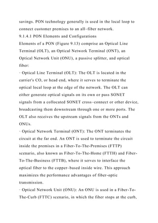
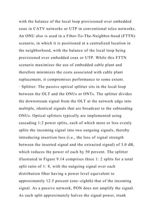
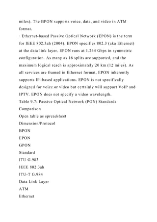
![to the premises.
· Brownfield deployments take place where there is existing
wireline infrastructure in the form of twisted pair, which is
removed to create space for PON. A brownfield deployment
typically takes the form of FTTN or FTTC, in which case the
distribution cables and Digital Loop Carrier (DLC) systems are
removed and replaced with optical fiber and PON ONUs. The
link from the ONU to the premises is in the form of ADSL or
perhaps VDSL over the embedded twisted pair, which yields a
hybrid fiber/copper configuration.
· Overlay deployments are those in which the new infrastructure
parallels that of the existing infrastructure. This approach
allows the service provider to construct the new system and
provide service to PON subscribers as required, while
continuing to serve others subscribing to more basic services
from the old cable plant. This phased approach generally is
preferred for FTTP deployments where there is existing
infrastructure [58, 59].
9.1.4.4 PON in Practice
The vast majority of the interest in PON is on the part of the
ILECs, particularly in the United States, where the CATV
providers have captured the greatest share of the broadband
access market with cable modem technology. As PON will once
again provide the ILECs with a competitive advantage, they are
deploying it aggressively in major markets, with the current](https://image.slidesharecdn.com/introductionthisisanindividualproject-221111011410-318fc01d/85/IntroductionThis-is-an-individual-project-Each-student-must-comp-docx-87-320.jpg)
![emphasis on BPON, although GPON will likely supplant it once
standards–based equipment becomes widely available. Render,
Vanderslice & Associates estimated in a report dated September
2005 that there were FTTH deployments in 652 communities in
43 states, with a total of 2.7 million potential customers passed
and 323,000 subscribers [60]. While I find the number of PON
subscribers a bit difficult to believe in the context of that time
frame, I certainly do not doubt that PON deployment is moving
forward quickly.
Verizon is by far the most aggressive of the U.S. ILECs with
respect to PON. Verizon's FiOS (Fiber-Optic Service) offering
is an FTTP architecture based on BPON and using ATM as the
underlying bearer protocol for data. Video is on a separate
wavelength, with all channels delivered simultaneously in
analog format. FiOS delivers an aggregate of 622 Mbps
downstream, with 32 splits, thereby yielding raw bandwidth of
over 19 Mbps to each premise. The service offerings are
detailed in Table 9.8.
Table 9.8: Verizon FiOS Internet Access Service Offerings [60]
Open table as spreadsheet
Downstream Rate (Mbps)
Upstream Rate (Mbps)
Monthly Rate[a]
5
2](https://image.slidesharecdn.com/introductionthisisanindividualproject-221111011410-318fc01d/85/IntroductionThis-is-an-individual-project-Each-student-must-comp-docx-88-320.jpg)
![$34.95
15
2
$44.95
30
5
$179.95
[a]Based on a one–year contract.
The Verizon service includes up to nine e-mail accounts,
Yahoo! or MSN Premium service, and 10 MB of personal Web
space. The inside wire to the wired or wireless router must be
upgraded to Cat 5 UTP. If a wireless router is used, 802.11b is
acceptable for the low–speed service offering but 802.11g is
required for the two higher speed offerings. The customer is
responsible for providing an electrical outlet close to the
location where the ONT is to be mounted in order to provide
power to the battery backup unit. The core offering of the
English language FiOS Premier TV is available at $ 39.95 per
month, while the Spanish language La Conexion is available for
$ 27.95, assuming that the subscriber also has Verizon voice
service. Prices are slightly higher for standalone TV service.
Various other packages, add–ons, on-demand content, and Pay–
Per–View (PPV) services are additional. As many as 350 TV
channels are available in total. Pricing is sensitive to bundling,
with the lowest prices offered to those subscribing to the full](https://image.slidesharecdn.com/introductionthisisanindividualproject-221111011410-318fc01d/85/IntroductionThis-is-an-individual-project-Each-student-must-comp-docx-89-320.jpg)
![triple play of voice, Internet access, and TV service. While
Verizon FiOS is not available everywhere in Verizon territory,
the company spent over US $ 1 billion in 2005 on FiOS–related
capital expenditures. At an estimated cost of $ 1250–$ 1350 per
premises for FTTP, $ 1 billion can go pretty quickly [61].
AT&T (previously SBC) largely is taking a dual approach in its
US $ 4 billion capital initiative known as Project Lightspeed. In
most new subdivisions and other greenfield scenarios, the
company will employ FTTP. In brownfield scenarios, the
company favors a hybrid fiber/copper approach, which it calls
Fiber-to-the-Node (FTTN), with each node delivering 20–25
Mbps to as many as 300–500 homes. AT&T will use copper to
provide ADSL and VDSL services from the node to the
customer premises. As the UTP portion of the loop is shortened
considerably in an FTTN scenario, many of the associated
performance issues are much reduced. BellSouth has taken a
relatively passive Fiber–to–the–Curb (FTTC) approach which is
quite complementary to the AT&T approach, and that fact quite
likely had some impact on the merger discussions between the
two companies [62, 63]. FTTN costs are estimated to be in the
range of $ 250 for overlays, which compares favorably with the
cost of FTTP.
Elsewhere, EPON is being aggressively deployed in Japan,
where it is known as GigE PON (Gigabit Ethernet PON), and is
the overwhelming choice throughout Asia. PON spending and](https://image.slidesharecdn.com/introductionthisisanindividualproject-221111011410-318fc01d/85/IntroductionThis-is-an-individual-project-Each-student-must-comp-docx-90-320.jpg)
![steps the voltage down from the MV level of 7200 V to the LV
level of 110/220 V used within the premises. The extractor
typically bypasses the transformer and couples the BPL signal
directly between the MV distribution line and the LV drop to
the premises. Alternatively, the extractor connects to a Wi-Fi
transceiver, and the final link to the customer premises is via
WLAN technology. The purest approach is to use an extractor
that amplifies the BPL signal enough that it can travel through
the transformer to the LV drop serving the premises, but this
technique is problematic. In any case, the extractor not only
serves as a demul-tiplexer for downstream signals from the
network to the premises but also as a multiplexer for upstream
signals.
Figure 9.15: Access BPL
The National Telecommunication and Information
Administration (NTIA) of the U.S. Department of Commerce
describes three BPL system types:
· System 1 injectors and extractors share a common frequency
band on the MV power lines for both upstream and downstream
communications through the use of a version of Orthogonal
Frequency Division Multiplexing (OFDM) specially tailored for
powerline environments. [Note: OFDM also is used in 802.11a
(Wi-Fi5) and 802.11g, ADSL, and 802.16 (WiMAX).] The
head–end injector couples the fiber to the MV line. Contention](https://image.slidesharecdn.com/introductionthisisanindividualproject-221111011410-318fc01d/85/IntroductionThis-is-an-individual-project-Each-student-must-comp-docx-94-320.jpg)
![for channel access is managed through Carrier Sense Multiple
Access with Collision Avoidance (CSMA/CA), the same
Medium Access Control (MAC) technique used in Wi-Fi LANs.
Thereby, multiple premises can share the same single–phase
MV line. This system may be sufficiently tolerant of
interference to permit multiple systems to be installed on
adjacent lines in a two–or three–phase MV distribution line.
· System 2 differs from System 1 only in that it bypasses the LV
drop altogether through the use of Wi-Fi technology.
· System 3 employs Direct-Sequence Spread Spectrum (DSSS)
in addition to Carrier Sense Multiple Access with Collision
Detection (CSMA/CD) for data transmission over the MV
distribution lines. DSSS is a packet radio technique in which the
signal is spread across a wide carrier frequency in a redundant
fashion. Thereby, multiple transmissions can share the same
wideband, with the transmissions separated from each other
through the use of a unique code sequence prepended to each
data packet. Multiple systems may be installed on adjacent lines
in a two–or three–phase MV distribution line. CSMA/CD is the
same MAC used in 802.3 (Ethernet) wired LANs [64].
Access BPL configurations can be either asymmetric or
symmetric in nature, with the aggregate amount of bandwidth
sensitive to the specific nature of the power grid, for example,
one-, two-, or three–phase MV distribution lines. As the BPL
local loop is shared, the aggregate bandwidth is shared, and the](https://image.slidesharecdn.com/introductionthisisanindividualproject-221111011410-318fc01d/85/IntroductionThis-is-an-individual-project-Each-student-must-comp-docx-95-320.jpg)
![measures [65–68].
Chapter 9 - Broadband Network Infrastructure
Telecommunications and Data Communications Handbook
by Ray Horak
John Wiley & Sons © 2007 Citation
Recommend?
9.2 SONET/SDH
Synchronous Optical Network (SONET) is a set of North
American standards for broadband communications over
SingleMode Fiber (SMF) optic transmission systems, thereby
enabling manufacturers to build equipment that supports full
inter-connectivity and interoperability. Synchronous Digital
Hierarchy (SDH) is the internationalized version of SONET, as](https://image.slidesharecdn.com/introductionthisisanindividualproject-221111011410-318fc01d/85/IntroductionThis-is-an-individual-project-Each-student-must-comp-docx-98-320.jpg)
![rules.) Therefore, the economic and technical benefits of a
multivendor market were limited and largely unrealized.
Initial SONET standardization efforts began in 1984, when MCI
(now part of Verizon) proposed the development of connectivity
standards, or midspan fiber meets, to the Interexchange Carrier
Compatibility Forum (ICCF). The ICCF then requested that the
Exchange Carriers Standards Association (ECSA) develop those
standards [69]. In 1985, Bellcore proposed SONET to the ANSI
T1X1 committee, and the process continued until final approval
for a much–revised SONET was gained in June 1988. The
resulting ANSI specification for SONET Phase 1 was released
in T1.105–1988 and T1.106–1988, specifying a basic
transmission level of 51.84 Mbps, which carries a signal
originating as the electrically based T3 of 45 Mbps, plus
additional overhead for optical processing and network
management.
The CCITT (now ITU–T) began the initial efforts to
internationalize SONET as SDH in 1986. In 1988, the CCITT
accepted the SONET standards, with modifications that were
mostly at the lower multiplexing levels. These differences
largely are due to the requirement to accommodate the
complexities of internetworking the disparate national and
regional networks. The ITU–T Recommendations referenced are
G.707, G.708, and G.709.
Standards work continues on SONET/SDH, with the](https://image.slidesharecdn.com/introductionthisisanindividualproject-221111011410-318fc01d/85/IntroductionThis-is-an-individual-project-Each-student-must-comp-docx-101-320.jpg)
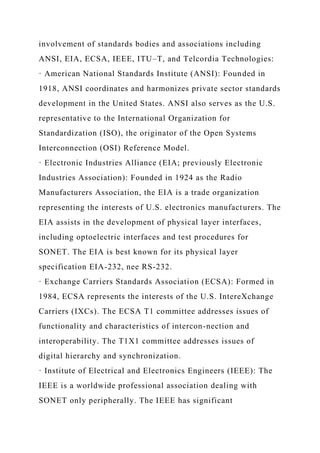
![defines Operations, Administration, Management, and
Provisioning (OAM&P) procedures and connectivity to B–
ISDN. Phase III provides all network management requirements
for midspan meet. Phase III also defines all network
management standard message sets (e.g., alarm state, circuit–
pack failure, and intermittent failure) and addressing schemes
for interconnection. Finally, Phase III provides for ring and
nested protection switching standards [69, 70].
9.2.2 SONET/SDH Transmission Hierarchy
SONET defines the Synchronous Transport Signal level N (STS-
N) as the electrical signal, which remains necessary until all–
optical switching is developed. When converted to an optical
signal for transport over a standard fiber-optic medium, the
term Optical Carrier N (OC-N) is applied. As noted in Table
9.9, the basic building block of the digital hierarchy is OC–1 at
51.84 Mbps and currently tops out at the OC–768 rate of 40
Gbps. Notably, the various STS levels are considerate of the
existing digital signal hierarchy, thereby achieving backward
compatibility with legacy systems. In other words and by way
of example, a T3 frame maps comfortably into an STS–1 signal
that becomes an OC–1 frame. Similarly, multiple T1 frames can
be aggregated to map into and form an STS–1 signal, which
then becomes an OC-1 frame.
Table 9.9: SONET/SDH Signal Hierarchy](https://image.slidesharecdn.com/introductionthisisanindividualproject-221111011410-318fc01d/85/IntroductionThis-is-an-individual-project-Each-student-must-comp-docx-105-320.jpg)
![Open table as spreadsheet
Optical Carrier Level[a]
SONET STS Level
SDH STM Level
Signaling Rate
Equivalent DS–3 (45–Mbps) Channels
Equivalent DS–0 (64–kbps) Channels
OC-1
STS-1
-
51.84 Mbps
1
672
OC-2
STS-2
-
103.68 Mbps
2
1,344
OC-3
STS-3
STM-1
155.52 Mbps
3
2,016](https://image.slidesharecdn.com/introductionthisisanindividualproject-221111011410-318fc01d/85/IntroductionThis-is-an-individual-project-Each-student-must-comp-docx-106-320.jpg)
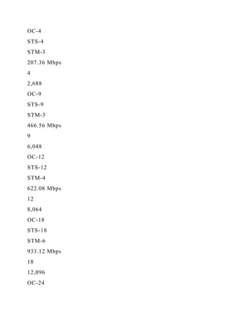
![STM-64
9.953 Gbps
192
129,024
OC-768
STS-768
STM-256
39.813 Gbps
768
516,096
OC-1536[b]
STS-1536
STM-512
79.626 Gbps
1,536
1,032,192
OC-3072 b
STS-3072
STM-1024
159.252 Gbps
3,072
2,064,384
[a]OC–2, OC–9, OC–18, OC–36, and OC–96 are considered to
be orphaned rates. OC–3 was defined by the CCITT as the basic
transport rate for Broadband ISDN (B–ISDN) [71].](https://image.slidesharecdn.com/introductionthisisanindividualproject-221111011410-318fc01d/85/IntroductionThis-is-an-individual-project-Each-student-must-comp-docx-109-320.jpg)
![[b]This level is not fully defined.
At OC–1, for example, a T3 bit stream of 44.736 Mbps is
padded and presented as an STS–1 signal of 51.84 Mbps, with
an actual maximum payload rate of 49.54 Mbps [72]. When
converted from an electrical signal to a fiber–optic photonic
signal, the bit stream is known as OC–1. The OC–1 comprises
810–byte frames transmitted at a rate of 8000 frames per
second, or every 125 μs, based on the requirement that a PCM–
encoded voice byte must be transmitted at that rate. SONET
levels fully define the range from OC–1 (51.84 Mbps) to OC–
768 (39.813 Gbps), which is composed of 768 OC–1 frames. At
OC–768, the entire string of 768 OC–1 frames must be
transmitted every 125 μs based on that same PCM requirement.
It merits reinforcing the point that SONET is based on T–
carrier, which is optimized for real–time, uncompressed voice.
Fractional speeds are achievable at virtually any level, as
subrate transmissions below OC–1 are multiplexed to form an
OC–1 channel. SONET terms of significance include the
following:
· Optical Carrier (OC) is the definition of the SONET optical
signal. The fully defined OC levels begin at OC–1 (51.84 Mbps)
and culminate in OC–768 (39.813 Gbps). All SONET/SDH
levels are expressed in multiples of OC–1.
· Synchronous Transport Signal (STS) is the electrical
equivalent of the SONET optical signal; it is known as](https://image.slidesharecdn.com/introductionthisisanindividualproject-221111011410-318fc01d/85/IntroductionThis-is-an-individual-project-Each-student-must-comp-docx-110-320.jpg)
![streams, selecting the better signal. Should the primary ring
fail, the secondary ring is already active in the reverse
direction.
· Line-switched rings involve either two or four fibers. The
single-ring implementation comprises two fibers, one of which
is active and the other of which is held in reserve. Traffic
moves in one direction across the active fiber. In the event of a
network failure, the backup ring is activated to enable
transmission in the reverse direction as well. A four–fiber
implementation, which is preferred and typical in carrier–class
networks, supports transmission in one direction over one fiber
in each of the two rings. By way of example, fibers 1 in rings 1
and 2 might transmit in a clockwise direction, while fibers 2 in
rings 1 and 2 transmit in a counterclockwise direction. The
second fiber in each ring acts to support transmission in the
reverse direction in the event of a failure in the primary ring.
Line–switched rings smaller than 1200 km in route distance
offer standard restoral intervals of 50 ms or less [73]. Larger
rings, such as long–haul transport rings in IXC networks,
involve longer restoral intervals due to the increased time of
signal propagation.
As illustrated in Figure 9.16, a typical SONET network involves
a number of rings operating at multiple speeds. The backbone,
for example, might run at the OC–192 nominal rate of 10 Gbps,
with subtended metro rings running at the OC–48 rate of 2.5](https://image.slidesharecdn.com/introductionthisisanindividualproject-221111011410-318fc01d/85/IntroductionThis-is-an-individual-project-Each-student-must-comp-docx-113-320.jpg)
![9.2.5 SONET Frame Format
The STS–1 frame (see Figure 9.17) is the basic building block
for SONET, much like the respective DS–1 frame formats in T–
carrier and E–carrier environments. The STS–1 frame can be
considered logically as a matrix of 9 rows of 90 octets, yielding
810 octets in total. The data are transmitted from top to bottom,
one row at a time and from left to right. SONET accommodates
payloads in increments of 765 octets, logically organized in
matrixes of 9 rows by 85 columns. The payload is contained
within a Synchronous Payload Envelope (SPE) in increments of
774 bytes (9 rows by 86 columns), with the additional column
attributable to Path OverHead (POH). Where superrate services
require more than a single STS–1, they are mapped into a higher
level, concatenated STS–N c, with the constituent STS–1s kept
together [74]. For example, a 135–Mbps B–ISDN H4 frame
requires a huge amount of contiguous, unbroken bandwidth.
SONET accommodates this requirement by linking three STS-1s
into an STS-3c [75].
The SPE, which contains the payload data, actually floats within
the SONET frame. While SONET is a synchronized
transmission system, with all devices relying on a common
clocking signal, variations in clocking can occur. Those
clocking variations can result from differences in local clocks,
thermal expansion and contraction in individual fiber–optic](https://image.slidesharecdn.com/introductionthisisanindividualproject-221111011410-318fc01d/85/IntroductionThis-is-an-individual-project-Each-student-must-comp-docx-116-320.jpg)
![cables, and other phenomena. Rather than buffering individual
frames to effect synchronization, floating mode operation
enables the network to adjust to frame float with the SPE
identified by the pointer. The floating mode reduces cost and
delay that would be caused by the use of buffers to synchronize
each frame and SPE exactly [75].
The SONET overhead structure mirrors that of the existing
digital carrier network for purposes of nonintrusive, end–to–end
network management. Overhead layers include transport
overhead (TO), which is further divided into section overhead,
line overhead, and path overhead.9.2.5.1 Section Overhead
Section Overhead (SOH) of 9 bytes provides for management of
optical network segments between Section-Terminating
Equipment (STE), which can be repeaters, Add/Drop
Multiplexers, or anything else that attaches to either end of a
fiber link. The repeaters can be stand alone or built into
switches, such as Digital Cross–Connect Systems (DCCSs or
DXCs). At the section layer, every repeater in the network
performs the SOH functions. These include framing, span
performance and error monitoring, and STS ID numbering.
These functions resemble those performed by traditional point–
to–point protocols such as SDLC and LAP–D. The 9 bytes of
SOH include
· 1 byte STS–1 signal ID
· 2 bytes Bit Interleaved Parity (BIP) for error monitoring](https://image.slidesharecdn.com/introductionthisisanindividualproject-221111011410-318fc01d/85/IntroductionThis-is-an-individual-project-Each-student-must-comp-docx-117-320.jpg)
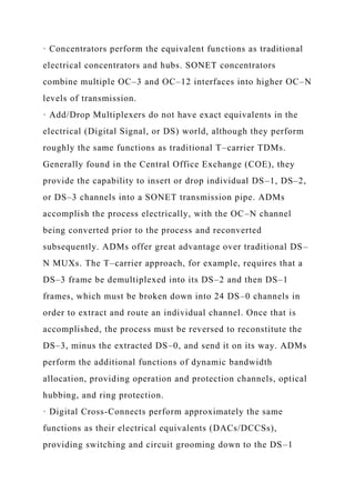
![where its many attributes can be put to full use. Particularly in a
convergence scenario, the carriers have the potential to realize
considerable cost savings by using a single–fiber infrastructure
in support of bandwidth–intensive video and image streams, in
addition to voice, facsimile, and voice–grade data traffic. The
value of SONET as a backbone technology is ever more evident
with the increasing penetration of broadband local loop
technologies such as ADSL, cable modems, PON, and WiMAX.
In a hybrid network configuration such as FTTN or FTTC, the
fiber portion of the loop from the CO to the DLC may be
SONET in nature.
It is interesting to track the developments in SONET speeds
over the past decade or so using a few select examples. In 1994,
Sprint announced the completion of the Silicon Valley Test
Track, linking seven companies and several learning institutions
to test ATM switching technologies. Plans called for the initial
OC–1 ring to be upgraded to OC–3 in early 1995 and to OC–12
later in the year [76]. Shortly thereafter, Sprint deployed the
first international SONET ring, linking New York City with
three cities in Canada. The capacity of that OC–48 (2.5 Gbps)
SONET ring increased to 10 Gbps through the use of Wave
Division Multiplexing (WDM) equipment in order to derive four
OC–48 channels [77]. In May 1996 AT&T announced plans to
beef up its network with WDM equipment to realize 20 Gbps
over OC–48 SONET fiber—an eightfold increase [78].](https://image.slidesharecdn.com/introductionthisisanindividualproject-221111011410-318fc01d/85/IntroductionThis-is-an-individual-project-Each-student-must-comp-docx-124-320.jpg)
![An interesting application of SONET technology is that of the
1996 Summer Olympics in Atlanta, Georgia. BellSouth, the
incumbent LEC, deployed 40 OC–48 SONET rings to transport
CD–quality voice, broadcast–quality video, and data
simultaneously to nine cities in the Greater Atlanta area where
the 26 various competitions took place. All information flowed
through the SONET pipes, including competition results,
accreditation, data, voice, and video. The uncompressed digital
video signals traveled to the International Broadcast Center,
where the signals were sold to other broadcasters to produce 40
worldwide video satellite feeds for approximately 3000 hours of
Olympic coverage [79].
A wide variety of carriers currently deploy fresh SONET
networks, and upgrade existing networks, to operate at OC–192
speeds of 10 Gbps. Certain portions of those networks operate
at OC–768 speeds of 40 Gbps. These carriers include not only
the incumbent voice and data IXCs but also the ILECs and
CLECs. Most impressive, perhaps, is the rate at which some of
the next–generation carriers deploy SONET. Literally from the
ground up, where justified by anticipated traffic, these carriers
commonly deploy SONET at speeds up to OC–192 in their
long–haul networks. Their overall costs range up to $ 10 billion
and more, in anticipation of huge volumes of voice, data, and
video traffic, using various combinations of circuit switching,
Frame Relay, ATM, and I P. XO Communications (previously](https://image.slidesharecdn.com/introductionthisisanindividualproject-221111011410-318fc01d/85/IntroductionThis-is-an-individual-project-Each-student-must-comp-docx-125-320.jpg)
![offers a cost–effective alternative for short–haul metropolitan
and local rings supporting applications such as GbE and 10GbE
[80, 81].
There also exist a number of nonstandard versions of DWDM.
In March 2001, for example, NEC announced a DWDM system
capable of supporting 273 lambdas, each modulated at OC–768
rates of 40 Gbps, yielding an aggregate 10.9 Tbps over a single
physical fiber [82]. As is the case with FDM in general, the
optical signals do not interfere with each, as they are separated
by frequency. In terms of bandwidth, therefore, WDM and
DWDM offer significant cost advantages over SONET, which
requires that the laser diode light sources and the Avalanche
PhotoDiode (APD) light detectors be upgraded to run at higher
speeds. Currently, 40 Gbps (OC–768) is the maximum speed
fully defined for SONET/SDH. At that speed, and certainly at
higher speeds, Polarization Mode Dispersion (PMD) becomes a
limiting factor, so dispersion compensators must be installed.
While there are technical limits to the speed at which the laser
diodes and APDs can operate and there also are finite speed
limitations to optical transmission, at least based on our current
understanding of the laws of physics, several higher levels are
in the process being defined by the ITU–T. OC–1536 is
intended to run at a nominal speed of 80 Gbps and OC-3072 at
160 Gbps. Some suggest that those levels will not be cost
effective in comparison to DWDM.](https://image.slidesharecdn.com/introductionthisisanindividualproject-221111011410-318fc01d/85/IntroductionThis-is-an-individual-project-Each-student-must-comp-docx-129-320.jpg)
![deployment of longer optical spans at the expense of some
additional overhead. The resulting line rate is approximately 7
percent higher than the corresponding SONET/SDH line rate,
which becomes the OTN payload. Table 9.10 lists the G.709
Optical Transport Unit (OTU) line rates and the matching
SONET/SDH line rates. In addition to the G.709 interface
specification, an interface for 10GbE clients exists, utilizing the
same overhead structure and FEC mechanism, which results in a
line rate of 11.095 Gbps [83].
Table 9.10: G.709 Line Rates and Corresponding SONET/SDH
Line Rates [83]
Open table as spreadsheet
G.709
SONET/SDH
Interface
Line Rate (Gbps)
OC/STM Level
Line Rate (Gbps)
OTU-1
2.666
OC-48/STM-16
2.488
OTU-2
10.709
OC-192/STM-64](https://image.slidesharecdn.com/introductionthisisanindividualproject-221111011410-318fc01d/85/IntroductionThis-is-an-individual-project-Each-student-must-comp-docx-133-320.jpg)
![simultaneously, which is much more efficient than the SONET
approach. RPR employs statistical packet multiplexing to
optimize the ring for packet data transport. This is unlike
SONET/SDH, which employs TDM and, therefore, is optimized
for PCM–based voice traffic. RPR further increases efficiency
through a spatial reuse mechanism. Older LAN ring protocols
such as Token Ring and FDDI require a data packet to traverse
the entire ring, even if the destination node is only a single hop
away from the originating node. RPR allows data inserted into
the ring to be sent directly to the destination node, where it
drops off and makes the bandwidth once again available to other
stations in the forward direction.
A Metropolitan Area Network (MAN) infrastructure technology,
RPR is largely oriented toward business–class data applications,
with emphasis on Ethernet. Notably, however, RPR traffic
classes provide sufficient Grade-of-Service (GoS) distinctions
to make it viable in appropriate triple–play implementations
[86–89].
Chapter 10: Broadband Network ServicesOVERVIEW
The speed of communications is wondrous to behold. It is also
true that speed can multiply the distribution of information that
we know to be untrue.](https://image.slidesharecdn.com/introductionthisisanindividualproject-221111011410-318fc01d/85/IntroductionThis-is-an-individual-project-Each-student-must-comp-docx-139-320.jpg)
![part of Verizon) in 1992, before suffering from competition
against Virtual Private Networks (VPNs) based on Internet
Protocol (IP). Clearly, users in the United States have had the
greatest appetite for Frame Relay, although it also enjoyed great
popularity in the European Union (EU) and remains widely
available at an international level.
10.1.1 Frame Relay Defined
Frame Relay is a network interface, or access, standard that was
defined in 1988 by the ITU-T in its I.122 Recommendation,
Framework for Providing Additional Packet Mode Bearer
Services. Access to a Frame Relay network is accomplished
using Link Access Procedure for Frame Mode Services (LAP-F),
as specified in Q.922. LAP-F is an adaptation of the Link
Access Procedure—Data channel (LAP-D) signaling protocol
developed for ISDN, as Frame Relay originally was intended as
an ISDN framing convention for a bearer service, that is,
information-bearing service. As Frame Relay standards address
Layers 1 and 2 of the Open Systems Interconnection (OSI)
Reference Model, they do not specify internal network
operations. As with X.25 packet networks, issues of packet
switching and transport are left to manufacturers and service
providers [1]. The vast majority of Frame Relay access is at
rates of Fractional T1, DS-0 (64 kbps) [2], and below because
the vast majority of connected sites are small, remote locations](https://image.slidesharecdn.com/introductionthisisanindividualproject-221111011410-318fc01d/85/IntroductionThis-is-an-individual-project-Each-student-must-comp-docx-143-320.jpg)
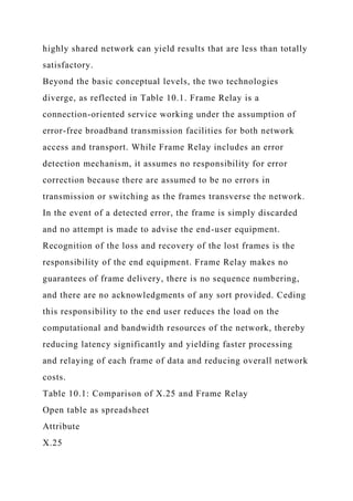
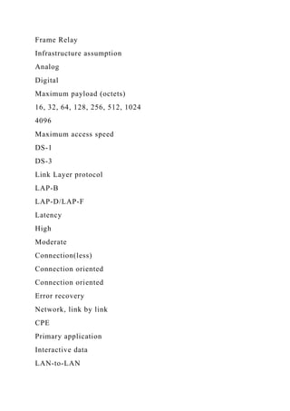
![PADs, T-carrier muxes, or even PBXs for dedicated networks.
More likely, they are incorporated into high-end routers serving
LANs. CO-based FRADs eliminate the end-user investment in
such equipment. Although they are limited in functionality as
they largely are intended to support the conversion of
Synchronous Data Link Control (SDLC) traffic to frame format,
CO-based FRADs offer advantages to user organizations
seeking to transition from dedicated networks connecting large
data centers [3–5].
· Frame Relay Network Devices (FRNDs) are Frame Relay
switches at the network side of the connection. The FRND
(pronounced friend) is provided by a friendly service provider,
which seems like an amicable arrangement. Frame Relay
switches are nodal processors capable of switching frames at
very high speed. They contain buffers for flow control purposes.
Within limits, the buffers can absorb incoming frames until the
switch can act on them as well as absorb outgoing frames until
the forward link becomes available. The switches contain very
high speed switching matrixes and internal buses. They have
sufficient intelligence, in the form of routing tables, to read the
control information embedded in the frame header and route the
frames correctly over the PVC identified previously in the call
set-up process. The nodal processors also have intelligence
sufficient to check for errors in the frame. Additionally, the
nodal processors may have the intelligence to prioritize certain](https://image.slidesharecdn.com/introductionthisisanindividualproject-221111011410-318fc01d/85/IntroductionThis-is-an-individual-project-Each-student-must-comp-docx-157-320.jpg)
![types of delay-sensitive traffic, such as SDLC and real-time
uncompressed voice and video. Since the switches perform no
error correction or protocol conversion functions, they act on
the frames very quickly, thereby minimizing latency. Frame
Relay nodal processors can be managed from a centralized
Network Operations Center (NOC), thereby enhancing the
scalability of the network [6]. The switch also may contain a
voice compression module. While Frame Relay is intended for
LAN internetworking, it can accommodate voice with varying
degrees of quality.
10.1.6 Frame Relay Protocol: Frame Structure
The Frame Relay protocol involves the relaying of frames of
user data across the network. In a typical data application, the
preponderance of the frame is payload in the form of user data,
with relatively little control information included. As illus-
trated in Figure 10.3, the five data fields in the ANSI T1.618
frame format comprise beginning and ending High-level Data
Link Control (HDLC) flags, an address field, an information
field, and a Frame Check Sequence (FCS), which is a CRC.
Although the Frame Relay protocol is a subset of the HDLC
protocol used in other data communications environments, it
lacks control information such as frame sequence number. In the
Frame Relay environment, it is the responsibility of the user to
identify and correct for frame sequence errors or missing frames](https://image.slidesharecdn.com/introductionthisisanindividualproject-221111011410-318fc01d/85/IntroductionThis-is-an-individual-project-Each-student-must-comp-docx-158-320.jpg)
![organizations, the network is subject to variable and somewhat
unpredictable levels of congestion. Indeed, it is designed for
congestion as a natural occurrence and in support of bursty
LAN-to-LAN internetworking applications, which are tolerant
of delay and loss and have the time and ability to adjust and
recover. This fact serves to reduce the overall cost of the
network service, although it compromises the level of
performance. This is a classic network optimization scenario in
which an appropriate balance is struck between cost and
performance. Congestion management is addressed through the
following parameters, specified in an addendum to ANSI T1.606
[6–8]:
· Access Rate: Maximum data rate of the access channel, as
defined by the bandwidth of the access link available for data
transmission (e.g., a DS-0 of 64 kbps, a Fractional T1 of 768
kbps, a full T1 of 1.536 Mbps, an E-1 of 2.048 Mbps, or a T3 of
44.736 Mbps). Data can be transmitted or received over the
access link at lesser rates, of course.
· Committed Information Rate (CIR): The data rate that the
network guaran-tees to handle across the Virtual Circuit (VC),
which can be either a PVC or an SVC, under normal conditions
over a period of time. While the standards do not specify the
time period, the CIR typically is an average data rate over a
period of a few seconds. The CIR is based on mutual agreement
between the carrier and the customer and should be based on the](https://image.slidesharecdn.com/introductionthisisanindividualproject-221111011410-318fc01d/85/IntroductionThis-is-an-individual-project-Each-student-must-comp-docx-163-320.jpg)
![hubs behind the FRAD have no ability to adjust other than
filling their buffers, which typically are highly limited in
capacity, if they exist at all. The originating terminal devices
and peripherals have no ability to adjust, other than filling their
very limited buffers, if any, and then simply stopping. If the
devices run TCP/IP, then TCP slows down when it detects a lost
frame.
· Implicit Congestion Notification: Inference by user equipment
that congestion has occurred. Such inference is triggered by
realization of the user device (e.g., FRAD, mainframe, or
server) that one or more frames have been lost. Based on
control mechanisms at the upper protocol layers of the end
devices, the frames are resent to recover from such loss.
Aside from the congestion mechanisms specified in the frame
standards, there are two types of congestion control algorithms.
Open-loop algorithms permit the acceptance of the frames with
no prior knowledge of the likelihood of their successful
delivery. Closed-loop algorithms prevent frames from entering
the network unless there is an extremely high probability of
their being accepted, transported, and delivered without discard.
The closed-loop algorithm fairly allocates backbone trunk
bandwidth among all the PVCs configured on a particular trunk
and in proportion to the CIRs [9]. Closed-loop networks clearly
are more sophisticated and offer better performance, although at
some additional cost.](https://image.slidesharecdn.com/introductionthisisanindividualproject-221111011410-318fc01d/85/IntroductionThis-is-an-individual-project-Each-student-must-comp-docx-167-320.jpg)
![quality voice (under conditions of low network congestion or
where the voice traffic remains within its CIR) at bit rates as
low as 8 kbps. Additionally, the Frame Relay Forum adopted
Conjugate Structure-Algebraic Code-Excited Linear Prediction
(CS-ACELP) as FRF.11. According to the Frame Relay Forum,
only 22 percent of normal speech comprises essential
components, with the balance comprising either pauses or
repetitive speech patterns [10].
· Code-Excited Linear Prediction (CELP): Key to CELP and its
derivatives is the creation and maintenance of a codebook,
which is a binary description of a set of voice samples.
Specifically, and as illustrated in Figure 10.5, CELP involves
the binary description of a set of 80 Pulse Code Modulation
(PCM) voice samples, representing 10 ms (10 milliseconds, or
1/100th of a second) of a voice stream, gathered in a buffer.
Then, the data set is compressed to remove silence and
redundancy, the volume level is normalized, and the resulting
data set is compared to a set of candidate shapes in the
codebook. The data transmitted across the network include the
index number of the selected code description and the average
loudness level of the set of samples. Every 10 ms, the code is
sent across the network in a block of 160 bits, yielding a data
rate of 16 kbps, which compares very favorably with PCM voice
over circuit-switched TDM networks at 64 kbps. The
compression ratio is 4: 1. At the receiving end of the](https://image.slidesharecdn.com/introductionthisisanindividualproject-221111011410-318fc01d/85/IntroductionThis-is-an-individual-project-Each-student-must-comp-docx-174-320.jpg)
![· Conjugate Structure-Algebraic Code-Excited Linear Prediction
(CS-ACELP):As defined in ITU-T G.729, ACELP improves on
the CELP concept through the algebraic expression, rather than
the numeric description, of each entry in the codebook. ACELP
yields quality that is considered to be as good as ADPCM, but
requiring bandwidth of only 8 kbps. CS-ACELP is geared
toward multichannel operation. Proprietary versions of ACELP
exist as well [11].
Other, nonstandard compression algorithms take the bit rate as
low as 4.8 kbps (or lower), but with considerable loss of
quality. Current ITU-T standards for voice compression used in
various VoFR codecs include those presented in Table 10.3, all
of which begin with PCM voice. In addition to the base
compression algorithms, various continuity algorithms are
employed to intelligently fill the void of missing or errored
compressed voice frames by stretching the previous voice
frames or blending several frames together.
Table 10.3: ITU-T Standard Voice Compression Algorithms
Open table as spreadsheet
Compression Algorithm, Year
ITU-T Recommendation
Bit Rate (kbps)
Compression Delay (ms)
Mean Opinion Score (MOS)[a]
Pulse Code](https://image.slidesharecdn.com/introductionthisisanindividualproject-221111011410-318fc01d/85/IntroductionThis-is-an-individual-project-Each-student-must-comp-docx-176-320.jpg)
![13.0-5.0
4.2
Conjugate Structure-Algebraic Code Excited Linear Prediction
(CS-ACELP), 1996
G.729 (FRF.11)
8
10.0
4.2
Source: [12–14].
[a]These are representative scores. Actual MOS values are
dependent on the skill with which the manufacturer implements
the algorithm, the specifics of the DSP, and other factors.
The perceived quality of the voice signal is based on exhaustive
tests, the most common of which is defined in the ITU-T P.800
specification, Methods for Subjective Determination of Voice
Quality. P.800 involves the subjective evaluation of preselected
voice samples of voice encoding and compression algorithms.
The evaluation is conducted by a panel of expert listeners
comprising a mixed group of men and women under controlled
conditions. The result of the evaluation is a Mean Opinion
Score (MOS) in a range from 1 to 5, with 1 being bad and 5
being excellent. The components of the MOS are as follows:
· Opinion Scale: conversation test (bad to excellent), difficulty
scale (yes or no)
· Opinion Scale: listening test (bad to excellent), listening effort](https://image.slidesharecdn.com/introductionthisisanindividualproject-221111011410-318fc01d/85/IntroductionThis-is-an-individual-project-Each-student-must-comp-docx-179-320.jpg)
![of a separate PVC for delay-sensitive traffic such as voice,
while others support multiplexing of voice data frames only
over the same PVC as that used in support of data. Some
manufacturers support both small frame sizes for voice and
large frame sizes for data, while others force all data into the
smaller frame size more appropriate for voice; the latter
approach forces all data into the less efficient (more overhead
intensive) frame size. Notably, VoFR FRADs are proprietary in
nature, thereby requiring a single-vendor VoFR network [12–
20].
In order to mitigate the inherent difficulties of transmitting
delay-sensitive voice traffic over Frame Relay, some
manufacturers and carriers offer various priority management
techniques. Several manufacturers of multifunction FRADs and
routers, for example, support the identification of high-priority
traffic in the frame header. Some service providers also offer
PVCs of varying levels of delay/priority, usually by mapping
the Frame Relay connection to an ATM connection with these
properties. Priority levels generally are defined as follows [21]:
· Real-Time Variable Frame Rate: Top priority; suited to delay-
sensitive, mission-critical applications such as voice and SNA;
premium pricing
· Non Real-Time Variable Frame Rate: No-priority designation;
suited to LAN and business-class Internet and intranet IP
traffic, which can tolerate some level of delay](https://image.slidesharecdn.com/introductionthisisanindividualproject-221111011410-318fc01d/85/IntroductionThis-is-an-individual-project-Each-student-must-comp-docx-181-320.jpg)
![· Available/Unspecified Frame Rate: Low-priority designation;
suited to Internet access, e-mail, file transfer, monitoring, and
other low-priority applications that can tolerate relatively
significant levels of delay
As it turns out, much of the voice carried over Frame Relay
links is, in fact, VoIP traffic. While a more detailed discussion
of VoIP occurs in Chapter 12, the subject of VoIP over Frame
Relay merits some discussion now. VoIP is very overhead
intensive, with a VoIP packet comprising 44 octets of various
headers and 20 octets consumed by the payload. As a result, a
64-kbps Frame Relay PVC can support only two G.729
compressed voice conversations. To improve the efficiency of
VoFR, the Frame Relay Forum developed FRF.20, Frame Relay
IP Header Compression Implementation Agreement. The
algorithm described in FRF.20 examines the 44 octets of VoIP
header, looking for redundancy and other opportunities to send
only a reference to the header, rather than the entire header.
This compression technique reduces the header to as few as two
to four octets, with the process reversed at the receiving end of
the circuit. Thereby, as many as five VoIP calls can be
supported over the same 64-kbps PVC [22].
VoFR efficiency can be improved further through subchannel
multiplexing. A single data link connection (DLCI) can support
multiple VoFR transmissions and multiple data transmissions
between two locations in an enterprise over a public or private](https://image.slidesharecdn.com/introductionthisisanindividualproject-221111011410-318fc01d/85/IntroductionThis-is-an-individual-project-Each-student-must-comp-docx-182-320.jpg)
![10.1.12 Frame Relay Attributes and Issues
FR unique characteristics offer some advantages over its
predecessor technologies of X.25, Switched 56/64 kbps, and
leased lines. Additionally, Frame Relay is widely available both
domestically and internationally. Also, the market is highly
competitive, which puts it in an advantageous position relative
to ATM. However, the recent market shift toward IP has caused
not only a slowing in Frame Relay demand but actually a
decline in Frame Relay service penetration. The International
Data Corporation (IDC) estimated that there were approximately
1.3 million Frame Relay ports in the United States at the end of
2005, but that number was expected to drop to 1.2 million in
2006 and fall to 751,000 in 2008. The IDC reports that not only
is Frame Relay decreasing but also carriers are now beginning
to eliminate it completely in favor of IP-based VPNs
[23].10.1.12.1 Frame Relay Advantages
Advantages of Frame Relay include its excellent support for
bandwidth-intensive data and image traffic. Even stream-
oriented traffic such as real-time voice and video can be
supported with reasonable quality. The absolute speed of Frame
Relay, its improved congestion control, and reduced latency
certainly are improvements over X.25 networks. Because Frame
Relay is protocol insensitive, it can carry virtually any form of
data in variable-size frames. Bandwidth on demand, within the
limit of the access line, is provided, generally with reasonable](https://image.slidesharecdn.com/introductionthisisanindividualproject-221111011410-318fc01d/85/IntroductionThis-is-an-individual-project-Each-student-must-comp-docx-185-320.jpg)
![Frame Relay, User Datagram Protocal (UDP) replaces TCP in
the protocol mix because there is no time to recover from loss
or error through retransmission, in any event.
Note that Frame Relay originally was marketed as a lower cost
replacement for leased lines and generally is provisioned on the
basis of PVCs, which are preordained source–destination paths.
Like private, leased-line networks, such paths are susceptible to
catastrophic failure and require backup. Backup PVCs can
satisfy this requirement because they are invoked virtually
immediately if the primary PVC fails. SVCs are more reliable,
as they automatically seek a reliable path on a call-by-call
basis. If the entire network fails, however, neither option is
satisfactory. For example, the entire AT&T Frame Relay
network failed in April 1998 for a period of up to 23 h,
depending on which press releases you believe. The problem
apparently had to do with bugs in some software upgrades on a
Cascade (now Cisco) switch, again depending on which press
releases you believe [24, 25]. A more effective backup strategy
in the event of such a catastrophic failure is carrier redundancy,
rather than PVC redundancy, or even SVCs. Some carriers also
offer redundancy in the form of redirected PVCs, which are
inactive PVCs that can be activated very quickly to direct
traffic around a point of failure in the network or in the access
loop. Redirected PVCs also can be used to redirect traffic to a
backup data center should the primary data center suffer a](https://image.slidesharecdn.com/introductionthisisanindividualproject-221111011410-318fc01d/85/IntroductionThis-is-an-individual-project-Each-student-must-comp-docx-188-320.jpg)
![2400–4800 bps. Using AT&T's InterSpan Frame Relay Service,
Apollo is able to establish end-to-end TCP/IP connections from
each agency to the Apollo reservations center. The service also
supports mesh networking between travel agencies, thereby
eliminating the requirement for all traffic to go through the
Apollo head end [26].
Voice over Frame Relay (VoFR), over both private and public
networks, is an option that has created a lot of interest.
Although the voice stream is subject to intrinsic Frame Relay
delays and although the service is overhead intensive for such
an application, it does enable the user organization to take
advantage of occasional excess bandwidth to connect voice for
free, or at least at very low cost once the cost of the voice
FRADs is factored into the equation. Through the use of
advanced compression techniques such as standards-based
ACELP and LD-CELP, VoFR can support good-quality voice at
16 bps, 8 kbps, and even 4.8 kbps.
10.2 SWITCHED MULTIMEGABIT DATA SERVICE
Switched Multimegabit Data Service (SMDS) is an offshoot of
the Distributed Queue Dual Bus (DQDB) technology defined by
the IEEE 802.6 standard for Metropolitan Area Networks
(MANs) as a means of extending the reach of the LAN across a
metropolitan area. The original work on the DQDB concept was
done at the University of Western Australia where it was known](https://image.slidesharecdn.com/introductionthisisanindividualproject-221111011410-318fc01d/85/IntroductionThis-is-an-individual-project-Each-student-must-comp-docx-191-320.jpg)
![as Queued Packet Synchronous Exchange (QPSX).
Subsequently, the original technology was licensed to QPSX
Ltd., formed by the University of Western Australia and
Telecom Australia [6]. The commercial success, although highly
limited, of SMDS is attributable to further development work by
Bellcore (now Telcordia Technologies) at the request of the
RBOCs. Bell Atlantic (now part of Verizon) introduced the first
commercial offering in 1992 at 5 Mbps based on a test
implementation at Temple University [27].
Since then, SMDS enjoyed limited, short-lived success in the
United States through deployment by most of the RBOCs and
GTE (now part of Verizon). As the RBOCs and their subsidiary
BOCs were primarily Local Exchange Carriers (LECs) generally
limited to providing service within the confines of the LATA at
the time, they exhibited particular interest in network
technologies that were appropriate for providing service in
confined geographic areas. The geographical limitation of
SMDS, therefore, did not pose a practical limitation for the
LECs.
SMDS was originally described by Bellcore (now Telcordia
Technologies) as a high-speed, connectionless, public, packet-
switching service that extends LAN-like performance beyond
the subscriber's premises, across a metropolitan or wide area.
SMDS is a MAN network service based on cell-switching
technology. Generally delivered over a SONET/SDH ring,](https://image.slidesharecdn.com/introductionthisisanindividualproject-221111011410-318fc01d/85/IntroductionThis-is-an-individual-project-Each-student-must-comp-docx-192-320.jpg)
![The automatic teller machine (usually called ATM), also known
by at least a dozen other names including cash machine, has
little to do with Asynchronous Transfer Mode (ATM), except
for the fact that the two technologies share a common acronym.
Actually, there are some ATMs that interconnect over networks
running the ATM protocol, but the real reason that I selected
this quote is that I couldn't find any interesting—much less
entertaining—quotes about the ATM protocol. This quote also
illustrates the dangers of using an Internet search engine when
researching a topic for a technical book. In the event that you
are interested in the history of the ATM, aka hole-in-the-wall
machine, Simjian's Bankmatic cash-dispensing machine was
installed in a City Bank of New York branch in New York City
in 1939. It was removed after only six months, due to lack of
acceptance. The modern ATM was invented in 1963 or 1968,
depending on which website you believe, by a trio of Docutel
engineers, Don Wentzel, Tom Barnes, and George Chastain. The
patent for that device was issued in 1973 and the first machine
was installed in a New York Chemical Bank [28–30].
Asynchronous Transfer Mode (ATM) was developed in concept
by the ITU-T as an outgrowth of ISDN standards that developed
in the early 1980s. While the concept of Narrowband ISDN (N-
ISDN) was intriguing, it soon became clear that the demand
would emerge for a wide range of bandwidth-intensive services
that would go beyond the scope of narrowband (N × 64-kbps)](https://image.slidesharecdn.com/introductionthisisanindividualproject-221111011410-318fc01d/85/IntroductionThis-is-an-individual-project-Each-student-must-comp-docx-195-320.jpg)
![the workstation, router, or ATM switch, data are organized into
48-octet cells. Each cell is prepended with a header of five
octets to create a cell of 53 octets. The cells are multiplexed
and contend for access to a broadband facility that ideally is
SONET in nature. In combination with SONET/SDH, ATM was
intended to be the ultimate and complete integrated network
solution, supporting a theoretically infinite range of services:
B-ISDN.
The small cell size reaps several advantages. First, it can
accommodate any form of data—digital voice, facsimile, data,
video, and so on. Second, the fixed length of the cell offers the
network switches the advantage of predictability, as compared
to a variable-length frame. Third, the fixed cell size facilitates
the implementation of switching functions in hardware (i.e.,
silicon), which enables processes to be accomplished at
significantly greater speed than does software, especially if
processing variable-size frames. These last two considerations
yield decreased delay, as data move through the switching
systems and across the transmission links in frequent little
blasts. Long, and especially variably long, frames occupy the
attention of the network for relatively long periods of time,
causing delay as other data wait to be processed.
ATM is the first network technology to offer truly guaranteed
bandwidth on demand, as the bandwidth can vary during the
course of the call [7]. True enough, other services offer](https://image.slidesharecdn.com/introductionthisisanindividualproject-221111011410-318fc01d/85/IntroductionThis-is-an-individual-project-Each-student-must-comp-docx-199-320.jpg)
![services include Broadband InterCarrier Interface (BICI),
Interim Local Management Interface (ILMI), LAN Emulation
(LANE), network management, Private Network Node Interface
(PNNI), signaling, Switched Multimegabit Data Service
(SMDS), IP over ATM, traffic management, and a number of
physical interfaces. The accord also limits the conditions under
which specifications are revised in order to reduce the potential
for future confusion [31,32].
10.3.3 Atm Access
Access to an ATM backbone network occurs at rates of DS-1 or
greater. Whether access is from an end-user CPE environment, a
Frame Relay or X.25 network switch, or an IP-based router, the
access rate is DS-1, DS-3, or a higher rate such as OC-3 (155
Mbps) or OC-12 (622 Mbps). Access is provided through a User
Network Interface (UNI) specified by the MFA Forum:
· User Network Interface (UNI) specifically refers to a UNI
between a user device and an ATM network. A private UNI is
employed in a private ATM network (e.g., LAN domain) and for
access to a public network. A public UNI is used between
switches in a public ATM network. As the UNI is cell based,
end-user CPE converts the user Protocol Data Units (PDUs) into
ATM PDUs and cells.
· Data Exchange Interface (DXI) is a private UNI for end-user
access to an ATM network from DTE/DCE such as a bridge,
router, or ATM DSU The DXI concept enables the sharing of](https://image.slidesharecdn.com/introductionthisisanindividualproject-221111011410-318fc01d/85/IntroductionThis-is-an-individual-project-Each-student-must-comp-docx-203-320.jpg)
![10.3.4 Atm Network and Equipment
The ATM network consists of CPE, Broadband Switching
Systems (BSSs), and interconnecting transmission facilities (see
Figure 10.7) [8, 33]:
Figure 10.7: ATM network
10.3.4.1 Customer Premises Equipment
Customer Premises Equipment(CPE) comprises Data Terminal
Equipment (DTE), Data Communications Equipment (DCE), and
voice and video switches, servers, and terminal equipment.
· DTE includes mainframe, midrange, and PC-server host
computers connected through the UNI.
· DCE comprises ATM-equipped bridges, switches, routers, and
gateways connected through the DXI UNI. A number of vendors
offer ATM premises switches. Such switches are used for LAN
interconnection, employing a highly redundant cell-switching
fabric capable of switching speeds that can reach as high as OC-
12 (622 Mbps).
· CPE includes ATM-based PBXs and video servers connected
via the UNI or the DXI. These devices were always somewhat
unusual and now have been superseded by IP-based devices.
10.3.4.2 Broadband Switching Systems
Broadband Switching Systems (BSSs)are carrier exchange
switches capable of broadband switching and transport. They
employ highly redundant cell-switching fabrics that currently](https://image.slidesharecdn.com/introductionthisisanindividualproject-221111011410-318fc01d/85/IntroductionThis-is-an-individual-project-Each-student-must-comp-docx-205-320.jpg)
![Category 5e (Cat 5e) UTP supports ATM speeds up to 155
Mbps. Cat 6 cable supports data rates up to 622 Mbps and
beyond.
Inverse Multiplexing over ATM (IMA) commonly is used for
high-speed access to a public ATM network when speeds above
T1/E-1 are required but T3/E-3 or fractional services are not
available. IMA also is used when a T3 or FT3 is not cost
effective, with the crossover point generally in the range of 12
Mbps or 8 T1s. With that crossover point in mind, IMA permits
as many as 8 T1s to link together to support aggregate
bandwidth of up to 12.288 Mbps (1.536 Mbps × 8). The ATM
cell stream is spread across the separate T1s in a round-robin
fashion and is resynchronized and reconstituted at the edge
switch. While the preferred communications link is in the form
of SONET optical fiber, it is not always available.
Significantly, IMA actually provides some benefit at this
bandwidth level in the form of redundancy. As an integrated
network service, ATM can support all information types but
typically requires an optical fiber link, which is susceptible to
catastrophic failure. Multiple T1 links provide some level of
redundancy in an IMA scenario, as all are unlikely to fail at the
same time, unless one very powerful backhoe manages to rip an
entire copper cable out of the ground. And, assuming that the
T1 circuits travel different physical routes, even backhoes pose
manageable threats [34].](https://image.slidesharecdn.com/introductionthisisanindividualproject-221111011410-318fc01d/85/IntroductionThis-is-an-individual-project-Each-student-must-comp-docx-207-320.jpg)
![10.3.5 Atm Protocols and Cell Structure
ATM is based on a 53-octet cell structure comprising 48 octets
of payload and 5 octets of header, as illustrated in Figure 10.8.
Contained within the payload, there also is some amount of
overhead in the form of a Convergence Sublayer (CS) header.
The choice of 48 octets was a compromise between the U.S.
Exchange Carriers Standards Association (ECSA) T1S1
committee and the ETSI. The ECSA promoted a cell size of 64
octets, while ETSI favored 32 octets, each reflecting the
bandwidth required for the parochial PCM voice-encoding
technique. The decision to use 48 octets was a perfect
mathematical compromise [35]. It is worth noting that the cell
size and composition are very overhead intensive, at about 10
percent, plus Convergence Sublayer and Layer 2 and Layer 3
headers. Standard PCM-encoded voice, at eight bits per sample,
can deal effectively with a small cell payload. Data, on the
other hand, generally is presented in much larger packets,
blocks, frames, and so on. Hence, the data world would have
preferred a much larger cell, while many in the voice world
actually would have preferred a smaller cell. So, 48 octets was a
perfect example of a compromise—none of the parties to the
negotiation was ecstatic about it, but all could accept it.
(Source: TA-NWT-00113. Copyright 1993 by Bellcore.)](https://image.slidesharecdn.com/introductionthisisanindividualproject-221111011410-318fc01d/85/IntroductionThis-is-an-individual-project-Each-student-must-comp-docx-208-320.jpg)
![channel identification, thereby ensuring that all cells travel the
same physical path and, therefore, arrive in sequence [36]. The
header is structured as follows:
· Generic Flow Control (GFC): Four bits that provide local flow
control but which field has no significance on an end-to-end
basis. The four-bit field supports 16 (2 4) GFC states.
Intermediate ATM switches overwrite this field with additional
Virtual Path Identifier (VPI) information [8]. In other words
and for example, GFC is significant in order to control data
flow across a UNI but is unnecessary at an NNI level. Flow
control is a congestion control mechanism which requires that
the various ATM switches and other equipment in both the
network core and at the edges communicate with each other to
determine the level of congestion along a defined path. If the
network suffers congestion in the path, the ATM switches can
buffer finite amounts of data; if the limits of the buffers are
exceeded, data will be lost. To avoid that potential loss, the
network must communicate with end-user devices to constrain
the amount of data entering the network so as not to invite
further congestion. A rate-based mechanism is an end-to-end
flow control scheme that considers resources edge to edge,
communicating the level of available resources through a
feedback loop. This approach requires that the transmitting end-
user device adjust its rate of transmission downward across the
UNI in consideration of congestion. A credit-based approach](https://image.slidesharecdn.com/introductionthisisanindividualproject-221111011410-318fc01d/85/IntroductionThis-is-an-individual-project-Each-student-must-comp-docx-210-320.jpg)
![information stream as originally transmitted. In other words, the
process of segmentation takes place at the ingress edge of the
ATM domain. Across the entire ATM network, from switch to
switch and from edge to edge, data flows in a cell stream. The
cells decouple and the data reassemble (reconstitute to original
form) at the egress edge of the ATM domain.
· AAL Types are supported by the functions of the Convergence
Sublayer (CS). There exist defined AAL Types 1, 2, 3/4, and 5,
each of which supports a specific class of traffic (see Table
10.4). AAL information is nested within the payload of user
information cells.
Table 10.4: ATM Adaptation Layer (AAL) Service
Classes/Categories
Open table as spreadsheet
ITU-T Service Class[a]
Class A
Class B
Class C
Class D
Class X
AAL type
1
2
3/4; 5 in message mode, only
3/4](https://image.slidesharecdn.com/introductionthisisanindividualproject-221111011410-318fc01d/85/IntroductionThis-is-an-individual-project-Each-student-must-comp-docx-215-320.jpg)
![Peak Cell Rate (PCR), Cell Delay Variation Tolerance (CDVT),
Minimum Cell Rate (MCR)
Quality-of-Service (QoS) parameters
Cell Delay Variation (CDV), Cell Transfer Delay (CTD), Cell
Loss Ratio (CLR)
Cell Loss Ratio (CLR)
Not specified
Example applications
Uncompressed voice, audio, and video; Circuit Emulation
Service (CES)
Compressed voice, audio, and video; SNA
X.25, FR, transaction processing
SMDS; LAN traffic; non-real-time buffered video
Signaling and control, network management, e-mail; (FTP);
World Wide Web, remote LAN access and telecommuting, LAN
internetworking; LAN Emulation (LANE); IP traffic including
VoIP (Voice over IP)
[a]The ITU-T service classes are listed here largely for purposes
of historical context. They generally are considered to be
obsolete, having been replaced by the MFA Forum service
categories.
· AAL Type 1 supports Class A traffic, which is connection-
oriented Constant Bit Rate (CBR) traffic timed between source
and sink. Such traffic is stream oriented and intolerant of delay.
Isochronous traffic such as digitized, uncompressed voice is](https://image.slidesharecdn.com/introductionthisisanindividualproject-221111011410-318fc01d/85/IntroductionThis-is-an-individual-project-Each-student-must-comp-docx-217-320.jpg)
![highly sensitive to delay [8]. AAL Type 3/4 supports message
mode and streaming mode service. Message mode service is
used for framed data in which only one Interface Data Unit
(IDU) is passed. In other words, it is a single-frame message of
up to 65,535 octets (2 16-1). Streaming mode service is used for
framed data in which multiple IDUs are passed in a stream. The
IDUs can be up to 65,535 octets, with a 10-bit CRC added at the
SAR layer as part of the trailer. As SMDS disappeared, this
AAL all but disappeared, in favor of AAL 5.
· AAL Type 5 supports Class C traffic in message mode only.
Such traffic is Variable Bit Rate (VBR) traffic with no timing
relationship between source and sink and consisting of only 1
IDU, as illustrated in Figure 10.11. AAL Type 5 also is known
as Simple and Efficient AAL (SEAL), as some of the overhead
has been stripped out of the Convergence Layer. AAL Type 5
initially was intended solely for use in signaling and control
(e.g., NNI applications) and network management (e.g., Local
Management Interface, or LMI). The IDUs can vary in length,
up to 65,535 octets. A 32-bit CRC is appended to the IDU at the
Convergence Layer as part of the trailer. AAL 5 also supports
Class X traffic, which is either Unspecified Bit Rate (UBR) or
Available Bit Rate (ABR). Such traffic is VBR and either
connection oriented or connectionless [37]. AAL 5 is used in
support of a wide variety of data traffic, including LAN
Emulation (LANE) and IP.](https://image.slidesharecdn.com/introductionthisisanindividualproject-221111011410-318fc01d/85/IntroductionThis-is-an-individual-project-Each-student-must-comp-docx-219-320.jpg)
![example, cannot be supported without the intervention of a
router. Also, a router or router function is required to support
communications between ELANs, which operate as closed user
groups, much like Virtual LANs (VLANs) [31, 38–40].
10.3.7 Multiprotocol over Atm
MultiProtocol Over ATM (MPOA) is a specification (July 1997)
from the ATM Forum designed to enhance LANE by enabling
interELAN communications without the intervention of a router
and the associated packet delay. MPOA provides high-
performance, scalable routing functionality over an ATM
platform. MPOA expands on LANE, Classical IP over ATM
(RFC 1577), and the IETF's Next Hop Resolution Protocol
(NHRP) in order to create a standardized notion of a virtual
router within an ATM network. Between any two MPOA-
capable end devices (e.g., MPOA-enhanced LANE hosts,
bridges, or switches), MPOA maps routed and bridged flows of
connectionless LAN traffic over cut-through ATM Switched
Virtual Channels (SVCs), offloading the packet-by-packet
processing steps performed by traditional routers. A route
server in the ATM network contains the core intelligence to
dynamically track the network topology and performance,
thereby providing guaranteed bandwidth, reduced latency, and
QoS. Since the routing intelligence is divorced from the packet-
forwarding function, MPOA offers a scalable and flexible
solution for LAN interconnectivity, corporate intranets, and](https://image.slidesharecdn.com/introductionthisisanindividualproject-221111011410-318fc01d/85/IntroductionThis-is-an-individual-project-Each-student-must-comp-docx-230-320.jpg)
![multimedia applications such as distance learning, desktop
videoconferencing, and collaborative work sessions. MPOA
supports protocols such as Ethernet, Token Ring, FDDI, and I P.
Through the NHRP protocol from the IETF, routing entities
within the MPOA network can intercommunicate to determine
the most appropriate path for a communication between edge
devices on an interELAN basis. MPOA essentially synthesizes
bridging and routing of connectionless interLAN traffic over a
connection-oriented ATM network [31, 38, 40].
10.3.8 Frame-Based Atm Transport over Ethernet
The Frame-based ATM Transport over Ethernet (FATE)
specification from the ATM Forum (February 2000 and July
2002) allows ATM services to be provided over Ethernet media
by transporting ATM data within an Ethernet frame. AAL5
applies in FATE applications. At this point, the specification is
defined only for the UNI, with FATE for NNI having been
targeted for further study. FATE has particular application in
the context of an ATM-based ADSL environment interfacing to
an Ethernet LAN through a switch or hub on the customer
premises [41].
10.3.9 Framed Atm over Sonet/Sdh Transport
The Framed ATM over SONET/SDH Transport (FAST)
specification from the ATM Forum (July 2000) defines the
mechanisms and procedures required to support the transport of
variable-length datagrams, known as ATM frames, over an ATM](https://image.slidesharecdn.com/introductionthisisanindividualproject-221111011410-318fc01d/85/IntroductionThis-is-an-individual-project-Each-student-must-comp-docx-231-320.jpg)
![infrastructure using SONET/SDH facilities. Interoperability
with existing ATM infrastructure is ensured through the use of
existing ATM control and management plane functions such as
signaling, routing, addressing, and OAM&P. The ATM Forum
has specified both FAST UNI and FAST NNI interfaces. The
FAST interfaces are functionally equivalent to their cell-based
counterparts with the exception of the maximum size of the
Service Data Unit (SDU), which is defined as a unit of interface
information whose identity is preserved from one end of a layer
connection to another.
Two encapsulation formats are defined. Frame encapsulation
supports the transmission of variable-length frames with a
maximum size of 9216 octets and using the AAL5 Adaptation
Layer. This approach involves minimal overhead. Cell
encapsulation involves the encapsulation of ATM cells within a
FAST frame, supporting an SDU with a maximum size of
65,535 octets, with the specific size sensitive to the AAL used.
FAST is similar to DXI (Data eXchange Interface) and FUNI
(Frame User Network Interface) with several major exceptions.
DXI and FUNI are designed for access to an ATM network over
relatively low speed plesiochronous transmission facilities,
while FAST is designed for access and/or interswitch trunking
over very high speed SONET/SDH transmission facilities [42].
10.3.10 Atm Attributes, Issues, and Applications
ATM clearly offered the great advantage of lots of bandwidth,](https://image.slidesharecdn.com/introductionthisisanindividualproject-221111011410-318fc01d/85/IntroductionThis-is-an-individual-project-Each-student-must-comp-docx-232-320.jpg)
![increase both complexity and cost while adding overhead.
At 10 Gbps, 10GbE is particularly suitable as a MAN
technology, although we always seem to be able to find a way to
consume more and more bandwidth closer and closer to the
desktop, where Ethernet rules. Estimates are that more than 95
percent of Internet traffic begins life as Ethernet frames [43].
10GbE will run in full-duplex (FDX) and over fiber only. Fiber
options include SONET and Resilient Packet Ring (RPR),
Coarse Wavelength Division Multiplexing (CWDM), and EPON,
which is restricted to the local loop level. As I discussed in
Chapter 9, RPR runs at SONET rates, either preserves the
SONET frame structure or uses Ethernet, and offers SONET-
like sub-50-ms cutover times but without the overhead-intensive
Automatic Protection Switching (APS) functionality of SONET.
The LAN interface specifies MultiMode Fiber (MMF) over
distances up to 300 m. The WAN interface calls for Single-
Mode Fiber (SMF) over distances up to 40 km. In the long term,
end-user applications for end-to-end 10GbE include Storage
Area Networks (SANs), data center disaster recovery, and
multimedia transport. In the short term, 10GbE is positioned as
a core switch technology for interconnecting GbE edge switches
providing native GbE services, as illustrated in Figure 10.12.
Internet access via 10GbE is the next logical step, which will
not be far behind [44–51].](https://image.slidesharecdn.com/introductionthisisanindividualproject-221111011410-318fc01d/85/IntroductionThis-is-an-individual-project-Each-student-must-comp-docx-237-320.jpg)
![The depth and complexity of AIN Software Release 1 caused the
telcos to move forward with their own various AIN releases,
known as Releases 0.X. All Releases 0.X are fully compatible
with Bellcore's Release 1.0, which likely will never be
implemented in its original and defined form. AIN Release 0.0
addresses basic call modeling functions for Service Switching
Points (SSPs) and database functions for Service Control Points
(SCPs). AIN Release 0.1 defines generic call model for
interaction between SSPs and SCPs; it includes features in
support of N-ISDN services. AIN Release 0.2 adds Intelligent
Peripherals (IPs) [52].
Characteristics of AINs include service creation toolkits, which
enable the creation of centralized logic residing in centralized
databases for the development and delivery of features across
the network. AINs support all ISDN features, including caller
ID, selective call blocking, and distinctive ringing. Finally,
AINs are intended to provide support for Personal
Communications Services (PCS), which permit subscribed
features to be supported across networks of all types. PCS, not
to be confused with the PCS cellular service, currently is
conceptual.
10.6.2 Service Creation Environment
The Service Creation Environment (SCE) is the key distinction
of an AIN. The SCE offers the carrier a toolkit for the
development of service offerings, which can be provided on a](https://image.slidesharecdn.com/introductionthisisanindividualproject-221111011410-318fc01d/85/IntroductionThis-is-an-individual-project-Each-student-must-comp-docx-244-320.jpg)
![known as Personal Assistants. Such systems also provide for
scheduling of follow-up calls, provide scheduled reminder
messages, and maintain contact lists [53].
· Follow-me service provides for call forwarding on a
predetermined schedule. A telecommuter, for example, might
have the network forward calls to the home office three days a
week during normal business hours. Calls would be directed to
the traditional office two days a week. Calls clearly outside of
normal business hours automatically would be directed to a
voice mail system.
· Computer security service automatically would serve to
provide secure access to networked hosts based on Calling Line
ID (CLID) and supplemented by authorization codes.
Additionally, the network automatically would keep a log of all
access and access attempts, thereby providing an audit trail.
· Call pickup service also known as call notification service,
provides for calls to be answered automatically by a voice
processor. The called party can be notified of a deposited voice
message by pager, fax, e-mail, or other means. The caller can
enter a privilege code provided by the called party to
distinguish the priority of the calling party. To pick up the call,
the called party dials a DISA (Direct Inward System Access)
port on the network switch and enters password codes in a
manner similar to that used to access contemporary voice mail
systems.](https://image.slidesharecdn.com/introductionthisisanindividualproject-221111011410-318fc01d/85/IntroductionThis-is-an-individual-project-Each-student-must-comp-docx-248-320.jpg)
![Middle East, The Bahamas, and South and Central America.
Ameritech (now part of SBC) conducted trials of its Call
Control Service as early as 1994, enabling residential customers
to block calls to specific numbers or to all numbers except those
on an allowed list. Widespread deployment of outgoing call
blocking is unlikely in the near future.
· Caller name is a variation of caller ID, more correctly known
as Calling Line ID (CLID), with linkage to directory services.
The incoming call is identified on a Visual Display Unit (VDU)
by originating number and associated directory listing. The
VDU can be built into the telephone or can be in the form of an
adjunct unit that sits between the telephone and the circuit. In a
CT (Computer Telephony) scenario, the VDU can be in the form
of a PC or computer workstation.
· Enhanced call return enables the subscriber to access what is,
in effect, a highly sophisticated, network-based voice mail
system. Bell Atlantic (now part of Verizon) trialed an offering
that enabled the user to call the system and enter security codes
to gain access to the switch and data stores. A voice
announcement identified the date, time, and phone number of
the last incoming call, at which point the return call could be
launched by pressing a number on the telephone keypad [54].
· Enhanced call routing is a network-based enhancement to toll-
free calling. The callers are presented with options that enable
them to specify their needs and then be connected with the](https://image.slidesharecdn.com/introductionthisisanindividualproject-221111011410-318fc01d/85/IntroductionThis-is-an-individual-project-Each-student-must-comp-docx-250-320.jpg)
![offices or individuals best able to satisfy them. MCI (Verizon)
and Stentor (Canada) conducted trials on such a system in early
1995, providing seamless interconnection between the U.S. and
Canadian networks [55].
· Call completion service enables the directory assistance
operator to extend the call automatically, perhaps at an
additional charge. This capability is offered by cellular
providers to avoid accidents caused by "driving and dialing."
· Number portability serves to provide portability of telephone
numbers such as INWATS and 900 numbers. This function is
utilized increasingly as the regulators insist on portability of
local numbers between LECs (Local Exchange Carriers). Local
Number Portability (LNP) is essential to facilitate local
competition, as decreed by the Telecommunications Act of
1996.
10.6.5 Ain Futures
The future of the AIN, at least as defined by Bellcore, is a bit
cloudy. Many of the large carriers have developed their own
versions of IN in support of toll-free services, calling card
verification, and various other services. Whether they will move
toward a standardized version is not clear, although it appears
unlikely. As AIN capabilities continue to roll out on a gradual
basis, you likely never will see headlines announcing the arrival
of AIN. Rather, it has crept into the networks and will continue
to do so. Driving forces over the last decade or so in the United](https://image.slidesharecdn.com/introductionthisisanindividualproject-221111011410-318fc01d/85/IntroductionThis-is-an-individual-project-Each-student-must-comp-docx-251-320.jpg)