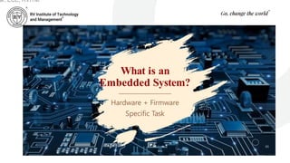
What is an
EmbeddedSystem?
Hardware + Firmware
Specific Task
03
ar, ECE, RVITM
4.
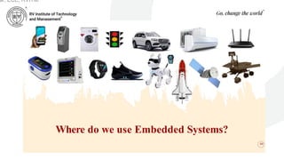
Where do weuse Embedded Systems?
04
ar, ECE, RVITM
5.
SYLLABUS
05
Embedded Systems
Definition, Embeddedsystems vs general computing systems, Classification of
Embedded Systems, Major application areas of Embedded Systems, Elements
of an Embedded System, Core of the Embedded System, Microprocessor vs
Microcontroller, RISC vs CISC
Sensors and Interfacing
Instrumentation and control systems, Transducers, Sensors, Actuators, LED, 7-
Segment LED Display.
ar, ECE, RVITM
What is anEmbedded System?
• An embedded system is an electronic/electro-
mechanical system designed to perform a specific
function and is a combination of both hardware
and firmware (software).
• Every embedded system is unique and the hardware
as well as the firmware is highly specialised to the
application domain.
ar, ECE, RVITM
9.
Embedded Systems vs.General
Computing Systems
• The computing revolution began with the general purpose
computing requirements. Later it was realised that the
general computing requirements are not sufficient for the
embedded computing requirements.
• The embedded computing requirements demand
‘something special’ in terms of response to stimuli,
meeting the computational deadlines, power efficiency,
limited memory capability, etc.
ar, ECE, RVITM
10.
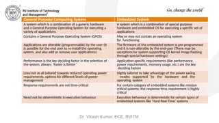
General Purpose ComputingSystem Embedded System
A system which is a combination of a generic hardware
and a General Purpose Operating System for executing a
variety of applications
A system which is a combination of special purpose
hardware and embedded OS for executing a specific set of
applications
Contains a General Purpose Operating System (GPOS) May or may not contain an operating system
for functioning
Applications are alterable (programmable) by the user (It
is possible for the end user to re-install the operating
system, and also add or remove user applications)
The firmware of the embedded system is pre-programmed
and it is non-alterable by the end-user (There may be
exceptions for system supporting OS kernel image flashing
through special hardware settings)
Performance is the key deciding factor in the selection of
the system. Always, ‘Faster is Better’
Application-specific requirements (like performance,
power requirements, memory usage, etc.) are the key
deciding factors
Less/not at all tailored towards reduced operating power
requirements, options for different levels of power
management
Highly tailored to take advantage of the power saving
modes supported by the hardware and the
operating system
Response requirements are not time-critical For certain category of embedded systems like mission
critical systems, the response time requirement is highly
critical
Need not be deterministic in execution behaviour Execution behaviour is deterministic for certain types of
embedded systems like ‘Hard Real Time’ systems
Dr. Vikash Kumar, ECE, RVITM
11.
Classification of EmbeddedSystems
• Some of the criteria used in the classification of
embedded systems are:
1. Based on generation
2. Complexity and performance requirements
3. Based on deterministic behaviour
4. Based on triggering
ar, ECE, RVITM
12.
Classification Based onGeneration
• First Generation
• Second Generation
• Third Generation
• Fourth Generation
• Next Generation
ar, ECE, RVITM
13.
Classification Based onGeneration (continued)
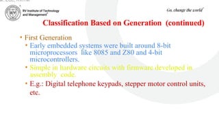
• First Generation
• Early embedded systems were built around 8-bit
microprocessors like 8085 and Z80 and 4-bit
microcontrollers.
• Simple in hardware circuits with firmware developed in
assembly code.
• E.g.: Digital telephone keypads, stepper motor control units,
etc.
ar, ECE, RVITM
14.
Classification Based onGeneration (continued)
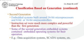
• Second Generation
• Embedded systems built around 16-bit microprocessors
and 8-bit or 16-bit microcontrollers.
• Instruction set were much more complex and powerful
than the first generation.
• Some of the second generation embedded systems
contained embedded operating systems for their
operation.
• E.g.: Data acquisition systems, SCADA systems, etc.
ar, ECE, RVITM
15.
Classification Based onGeneration (continued)
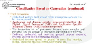
• Third Generation
• Embedded systems built around 32-bit microprocessors and 16-
bit microcontrollers.
• Application and domain specific processors/controllers like
Digital Signal Processors (DSP) and Application Specific
Integrated Circuits (ASICs) came into picture.
• The instruction set of processors became more complex and
powerful and the concept of instruction pipelining also evolved.
• Dedicated embedded real time and general purpose operating
systems entered into the embedded market.
• Embedded systems spread its ground to areas like robotics,
media, industrial process control, networking, etc.
ar, ECE, RVITM
16.
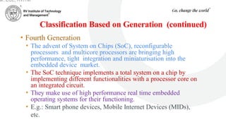
Classification Based onGeneration (continued)
• Fourth Generation
• The advent of System on Chips (SoC), reconfigurable
processors and multicore processors are bringing high
performance, tight integration and miniaturisation into the
embedded device market.
• The SoC technique implements a total system on a chip by
implementing different functionalities with a processor core on
an integrated circuit.
• They make use of high performance real time embedded
operating systems for their functioning.
• E.g.: Smart phone devices, Mobile Internet Devices (MIDs),
etc.
ar, ECE, RVITM
17.
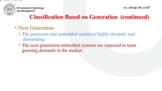
Classification Based onGeneration (continued)
• Next Generation
• The processor and embedded market is highly dynamic and
demanding.
• The next generation embedded systems are expected to meet
growing demands in the market.
ar, ECE, RVITM
18.
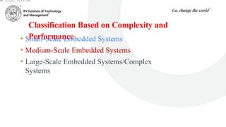
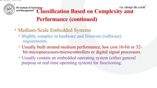
Classification Based onComplexity and
Performance
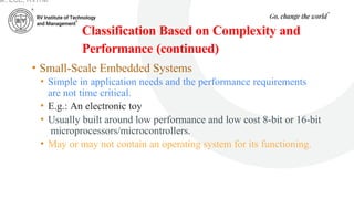
• Small-Scale Embedded Systems
• Medium-Scale Embedded Systems
• Large-Scale Embedded Systems/Complex
Systems
ar, ECE, RVITM
19.
Classification Based onComplexity and
Performance (continued)
• Small-Scale Embedded Systems
• Simple in application needs and the performance requirements
are not time critical.
• E.g.: An electronic toy
• Usually built around low performance and low cost 8-bit or 16-bit
microprocessors/microcontrollers.
• May or may not contain an operating system for its functioning.
ar, ECE, RVITM
20.
Classification Based onComplexity and
Performance (continued)
• Medium-Scale Embedded Systems
• Slightly complex in hardware and firmware (software)
requirements.
• Usually built around medium performance, low cost 16-bit or 32-
bit microprocessors/microcontrollers or digital signal processors.
• Usually contain an embedded operating system (either general
purpose or real time operating system) for functioning.
ar, ECE, RVITM
21.
Classification Based onComplexity and
Performance (continued)
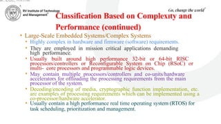
• Large-Scale Embedded Systems/Complex Systems
• Highly complex in hardware and firmware (software) requirements.
• They are employed in mission critical applications demanding
high performance.
• Usually built around high performance 32-bit or 64-bit RISC
processors/controllers or Reconfigurable System on Chip (RSoC) or
multi- core processors and programmable logic devices.
• May contain multiple processors/controllers and co-units/hardware
accelerators for offloading the processing requirements from the main
processor of the system.
• Decoding/encoding of media, cryptographic function implementation, etc.
are examples of processing requirements which can be implemented using a
co-processor/hardware accelerator.
• Usually contain a high performance real time operating system (RTOS) for
task scheduling, prioritization and management.
ar, ECE, RVITM
22.
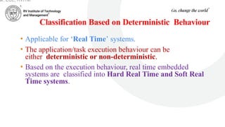
Classification Based onDeterministic Behaviour
• Applicable for ‘Real Time’ systems.
• The application/task execution behaviour can be
either deterministic or non-deterministic.
• Based on the execution behaviour, real time embedded
systems are classified into Hard Real Time and Soft Real
Time systems.
ar, ECE, RVITM
23.
Classification Based onTriggering
• Embedded systems which are ‘Reactive’ in nature (like
process control systems in industrial control applications)
can be classified based on the trigger.
• Reactive systems can be either event-triggered or time-
triggered.
ar, ECE, RVITM
24.
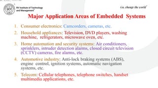
Major Application Areasof Embedded Systems
1. Consumer electronics: Camcorders, cameras, etc.
2. Household appliances: Television, DVD players, washing
machine, refrigerators, microwave oven, etc.
3. Home automation and security systems: Air conditioners,
sprinklers, intruder detection alarms, closed circuit television
(CCTV) cameras, fire alarms, etc.
4. Automotive industry: Anti-lock braking systems (ABS),
engine control, ignition systems, automatic navigation
systems, etc.
5. Telecom: Cellular telephones, telephone switches, handset
multimedia applications, etc.
ar, ECE, RVITM
25.
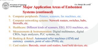
Major Application Areasof Embedded
Systems (continued)
6. Computer peripherals: Printers, scanners, fax machines, etc.
7. Computer networking systems: Network routers, switches, hubs,
firewalls, etc.
8. Healthcare: Different kinds of scanners, EEG, ECG machines, etc.
9. Measurements & Instrumentation: Digital multimeters, digital
CROs, logic analyzers, PLC systems, etc.
10. Banking & Retail: Automated teller machines (ATM) and
currency counters, point of sales (POS), etc.
11. Card readers: Barcode, smart card readers, hand held devices, etc.
ar, ECE, RVITM
26.
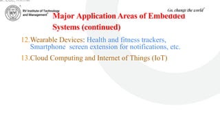
Major Application Areasof Embedded
Systems (continued)
12.Wearable Devices: Health and fitness trackers,
Smartphone screen extension for notifications, etc.
13.Cloud Computing and Internet of Things (IoT)
ar, ECE, RVITM
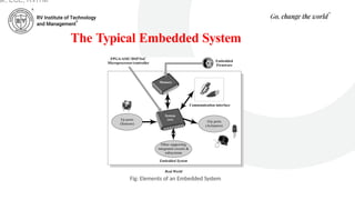
The Typical EmbeddedSystem (continued)
• It contains a single chip controller, which acts as the master brain of
the system.
• The controller can be
A microprocessor or
A microcontroller or
A Field Programmable Gate Array (FPGA) device or
A Digital Signal Processor (DSP) or
An Application Specific Integrated Circuit (ASIC)/Application
Specific Standard Product (ASSP)
ar, ECE, RVITM
30.
The Typical EmbeddedSystem (continued)
• An embedded system can be viewed as a reactive system.
• The control is achieved by processing the information
coming from the sensors and user interfaces, and
controlling some actuators that regulate the physical
variable.
• Key boards, push button switches, etc. are examples for
common user interface input devices.
• LEDs, liquid crystal displays, piezoelectric buzzers, etc. are
examples for common user interface output devices for a
typical embedded system.
ar, ECE, RVITM
31.
The Typical EmbeddedSystem (continued)
• The memory of the system is responsible for holding the control algorithm and other
important configuration details.
• For most of embedded systems, the memory for storing the algorithm or configuration data is
of fixed type, which is a kind of Read Only Memory (ROM).
• It is not available for the end user for modifications
• The memory is protected from unwanted user interaction by implementing some kind of
memory protection mechanism.
• The most common types of memories used in embedded systems for control algorithm
storage are OTP, PROM, UVEPROM, EEPROM and FLASH.
• Sometimes the system requires temporary memory for performing arithmetic operations or
control algorithm execution and this type of memory is known as "working memory".
• Random Access Memory (RAM) is used in most of the systems as the working memory.
• Various types of RAM like SRAM, DRAM and NVRAM are used for this purpose.
ar, ECE, RVITM
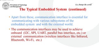
32.
The Typical EmbeddedSystem (continued)
• Apart from these, communication interface is essential for
communicating with various subsystems of the
embedded system and with the external world.
• The communication interfaces may be used to achieve
onboard (I2C, SPI, UART, parallel bus interface, etc.) or
external communication (wireless interfaces like Infrared,
Bluetooth, Wi-Fi, etc.)
ar, ECE, RVITM
33.
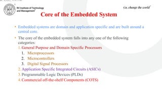
Core of theEmbedded System
• Embedded systems are domain and application specific and are built around a
central core.
• The core of the embedded system falls into any one of the following
categories:
1.General Purpose and Domain Specific Processors
1. Microprocessors
2. Microcontrollers
3. Digital Signal Processors
2.Application Specific Integrated Circuits (ASICs)
3.Programmable Logic Devices (PLDs)
4.Commercial off-the-shelf Components (COTS)
ar, ECE, RVITM
34.
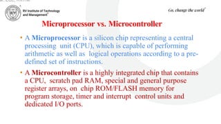
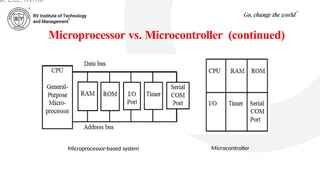
Microprocessor vs. Microcontroller
•A Microprocessor is a silicon chip representing a central
processing unit (CPU), which is capable of performing
arithmetic as well as logical operations according to a pre-
defined set of instructions.
• A Microcontroller is a highly integrated chip that contains
a CPU, scratch pad RAM, special and general purpose
register arrays, on chip ROM/FLASH memory for
program storage, timer and interrupt control units and
dedicated I/O ports.
ar, ECE, RVITM
35.
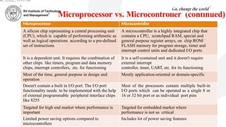
Microprocessor vs. Microcontroller(continued)
Microprocessor Microcontroller
A silicon chip representing a central processing unit
(CPU), which is capable of performing arithmetic as
well as logical operations according to a pre-defined
set of instructions
A microcontroller is a highly integrated chip that
contains a CPU, scratchpad RAM, special and
general purpose register arrays, on chip ROM/
FLASH memory for program storage, timer and
interrupt control units and dedicated I/O ports
It is a dependent unit. It requires the combination of
other chips like timers, program and data memory
chips, interrupt controllers, etc. for functioning
It is a self-contained unit and it doesn't require
external interrupt
controller, timer, UART, etc. for its functioning
Most of the time, general purpose in design and
operation
Mostly application-oriented or domain-specific
Doesn't contain a built in I/O port. The I/O port
functionality needs to be implemented with the help
of external programmable peripheral interface chips
like 8255
Most of the processors contain multiple built-in
I/O ports which can be operated as a single 8 or
16 or 32 bit port or as individual port pins
Targeted for high end market where performance is
important
Targeted for embedded market where
performance is not so critical
Limited power saving options compared to
microcontrollers
Includes lot of power saving features
ar, ECE, RVITM
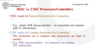
RISC vs. CISCProcessors/Controllers
• RISC stands for Reduced Instruction Set Computing.
• All RISC processors/controllers possess lesser number of
instructions, typically in the range of 30 to 40.
• E.g.: Atmel AVR microcontroller – its instruction set contains
only 32 instructions.
• CISC stands for Complex Instruction Set Computing.
• The instruction set is complex and instructions are high in
number.
• E.g.: 8051 microcontroller – its instruction set contains
255 instructions.
ar, ECE, RVITM
38.
RISC CISC
Lesser numberof instructions Greater number of instructions
Instruction pipelining and increased execution speed Generally no instruction pipelining feature
Orthogonal instruction set (Allows each instruction to
operate on any register and use any addressing mode)
Non-orthogonal instruction set (All instructions are not
allowed to operate on any register and use any addressing
mode. It is instruction-specific)
Operations are performed on registers only, the only
memory operations are load and store
Operations are performed on registers or memory depending on
the instruction
A large number of registers are available Limited number of general purpose registers
Programmer needs to write more code to execute a task
since the instructions are simpler ones
Instructions are like macros in C language. A programmer can
achieve the desired functionality with a single instruction
which in turn provides the effect of using more simpler single
instructions in RISC
Single, fixed length instructions Variable length instructions
Less silicon usage and pin count More silicon usage since more additional decoder logic is
required to implement the complex instruction decoding
With Harvard Architecture Can be Harvard or Von-Neumann Architecture
ar, ECE, RVITM
Sensors and Actuators
•An embedded system is in constant interaction with the real world
and the controlling/monitoring functions executed by the embedded
system is achieved in accordance with the changes happening to the
real world.
• The changes in system environment or variables are detected by the
sensors connected to the input port of the embedded system.
• If the embedded system is designed for any controlling purpose, the
system will produce some changes in the controlling variable to bring
the controlled variable to the desired value.
• It is achieved through an actuator connected to the output port of the
embedded system.
ar, ECE, RVITM
41.
Sensors and Actuators(continued)
• A sensor is a transducer device that converts energy from
one form to another for any measurement or control
purpose.
• E.g.: Temperature sensor, magnetic hall effect sensor,
humidity sensor, etc.
• An actuator is a form of transducer device (mechanical or
electrical) which converts signals to corresponding
physical action (motion).
• Actuator acts as an output device.
• E.g.: Stepper motor
ar, ECE, RVITM
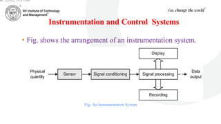
Instrumentation and ControlSystems
Fig: An Instrumentation System
• Fig. shows the arrangement of an instrumentation system.
ar, ECE, RVITM
44.
Instrumentation and ControlSystems (continued)
• The physical quantity to be measured (e.g. temperature) acts
upon a sensor that produces an electrical output signal.
• This signal is an electrical analog of the physical input but there
may not be a linear relationship between the physical quantity
and its electrical equivalent.
• Because of this and since the output produced by the sensor may be
small or may suffer from the presence of noise (i.e. unwanted
signals), further signal conditioning will be required before the
signal will be at an acceptable level and in an acceptable form for
signal processing, display and recording.
• Furthermore, because the signal processing may use digital rather
than analog signals an additional stage of analog-to-digital
conversion may be required.
ar, ECE, RVITM
45.
Instrumentation and ControlSystems (continued)
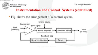
• Fig. shows the arrangement of a control system.
Fig: A Control System
ar, ECE, RVITM
46.
Instrumentation and ControlSystems (continued)
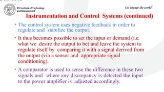
• The control system uses negative feedback in order to
regulate and stabilize the output.
• It thus becomes possible to set the input or demand (i.e.
what we desire the output to be) and leave the system to
regulate itself by comparing it with a signal derived from
the output (via a sensor and appropriate signal
conditioning).
• A comparator is used to sense the difference in these two
signals and where any discrepancy is detected the input
to the power amplifier is adjusted accordingly.
ar, ECE, RVITM
47.
Instrumentation and ControlSystems
(continued)
• This signal is referred to as an error signal (it should be
zero when the output exactly matches the demand).
• The input (demand) is often derived from a simple
potentiometer connected across a stable d.c. voltage
source while the controlled device can take many forms
(e.g. a d.c. motor, linear actuator, heater, etc.).
ar, ECE, RVITM
48.
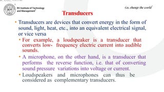
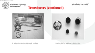
Transducers
• Transducers aredevices that convert energy in the form of
sound, light, heat, etc., into an equivalent electrical signal,
or vice versa.
• For example, a loudspeaker is a transducer that
converts low- frequency electric current into audible
sounds.
• A microphone, on the other hand, is a transducer that
performs the reverse function, i.e. that of converting
sound pressure variations into voltage or current.
• Loudspeakers and microphones can thus be
considered as complementary transducers.
ar, ECE, RVITM
49.
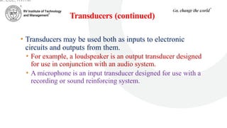
Transducers (continued)
• Transducersmay be used both as inputs to electronic
circuits and outputs from them.
• For example, a loudspeaker is an output transducer designed
for use in conjunction with an audio system.
• A microphone is an input transducer designed for use with a
recording or sound reinforcing system.
ar, ECE, RVITM
Sensors
• A sensoris a special kind of transducer that is used to generate
an input signal to a measurement, instrumentation or control
system.
• The signal produced by a sensor is an electrical analogy of a
physical quantity, such as distance, velocity, acceleration,
temperature, pressure, light level, etc.
• The signals returned from a sensor, together with control inputs
from the user or controller (as appropriate) will subsequently be
used to determine the output from the system.
• The choice of sensor is governed by a number of factors
including accuracy, resolution, cost and physical size.
ar, ECE, RVITM
52.
Sensors (continued)
ar, ECE,RVITM
• Sensors can be categorized as either active or passive.
• An active sensor generates a current or voltage
output.
• A passive transducer requires a source of current or
voltage and it modifies this in some way (e.g. by virtue
of a change in the sensor’s resistance).
• The result may still be a voltage or current but it is not
generated by the sensor on its own.
53.
Sensors (continued)
• Sensorscan also be classed as either digital or analog.
• The output of a digital sensor can exist in only two
discrete states, either ‘on’ or ‘off’, ‘low’ or ‘high’,
‘logic 1’ or ‘logic 0’, etc.
• The output of an analog sensor can take any one of an
infinite number of voltage or current levels. It is thus
said to be continuously variable.
ar, ECE, RVITM
Actuators
• An actuatoris a form of transducer device (mechanical or electrical)
which converts signals to corresponding physical action (motion).
ar, ECE, RVITM
https://youtu.be/LHn7O6PUaoY
56.
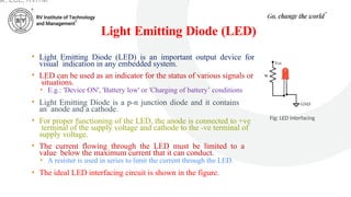
Light Emitting Diode(LED)
• Light Emitting Diode (LED) is an important output device for
visual indication in any embedded system.
• LED can be used as an indicator for the status of various signals or
situations.
• E.g.: 'Device ON', 'Battery low' or 'Charging of battery’ conditions
• Light Emitting Diode is a p-n junction diode and it contains
an anode and a cathode.
• For proper functioning of the LED, the anode is connected to +ve
terminal of the supply voltage and cathode to the -ve terminal of
supply voltage.
• The current flowing through the LED must be limited to a
value below the maximum current that it can conduct.
• A resister is used in series to limit the current through the LED.
• The ideal LED interfacing circuit is shown in the figure.
Fig: LED interfacing
ar, ECE, RVITM
57.
Light Emitting Diode(LED) (continued)
• LEDs can be interfaced to the port pin of a processor/controller in two ways:
• In the first method, the anode is directly connected to the port pin and the
port pin drives the LED.
• The port pin 'sources' current to the LED when the port pin is at logic High
(Logic ‘1’).
• In the second method, the cathode of the LED is connected to the port pin of
the processor/controller and the anode to the supply voltage through a
current limiting resistor.
• The LED is turned on when the port pin is at logic Low (Logic '0’).
• Here the port pin 'sinks' current.
ar, ECE, RVITM
58.
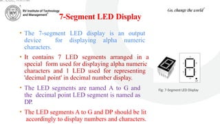
7-Segment LED Display
•The 7-segment LED display is an output
device for displaying alpha numeric
characters.
• It contains 7 LED segments arranged in a
special form used for displaying alpha numeric
characters and 1 LED used for representing
'decimal point' in decimal number display.
• The LED segments are named A to G and
the decimal point LED segment is named as
DP.
• The LED segments A to G and DP should be lit
accordingly to display numbers and characters.
Fig: 7-Segment LED Display
ar, ECE, RVITM
59.
7-Segment LED Display(continued)
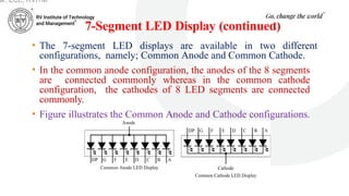
• The 7-segment LED displays are available in two different
configurations, namely; Common Anode and Common Cathode.
• In the common anode configuration, the anodes of the 8 segments
are connected commonly whereas in the common cathode
configuration, the cathodes of 8 LED segments are connected
commonly.
• Figure illustrates the Common Anode and Cathode configurations.
ar, ECE, RVITM
60.
7-Segment LED Display(continued)
• Based on the configuration of the 7-segment LED unit, the LED
segment's anode or cathode is connected to the port of the
processor/controller in the order 'A' segment to the least significant port
pin and DP segment to the most significant port pin.
• The current flow through each of the LED segments should be limited to
the maximum value supported by the LED display unit.
• The typical value is 20mA.
• The current can be limited by connecting a current limiting resistor to the
anode or cathode of each segment.
• 7-segment LED display is used in low cost embedded applications
like Public telephone call monitoring devices, point of sale terminals,
etc.
ar, ECE, RVITM