Structural Requirements
and Constraints
1.Minimum mass requirements
2. Volume requirements
3. Strength requirements
4. Stiffness requirements
5. Requirements for dimensional accuracy and
stability
6. Requirements for Production and
Processing Facility
7. Unification requirements
5.
Mechanical Design
Process
The processbegins with an identification of a need and a
decision to do something about it. After many iterations,
the process ends with the presentation of the plans for
satisfying the need.
Depending on the nature of the design task, several design
phases may be repeated throughout the life of the
product, from inception to termination.
6.
Mechanical Design
Process
In thetypical mechanical design process, there are 7 steps
involved:
1. Problem Definition
2. Conceptual Design
3. Preliminary Design
4. Detailed Design
5. Prototyping, Testing & Validation
6. Production & Implementation
7. Post-Launch Evaluation
7.
Mechanical Design
Process
Goal:Define the design challenge.
Activities:
• Understand user needs and market gaps.
• Gather functional, performance, and regulatory
requirements.
• Research existing solutions and constraints (cost,
materials, time).
Output: Clear problem statement and design
specifications.
1.Problem Definition
8.
Mechanical Design
Process
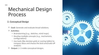
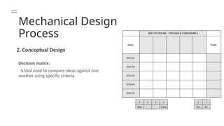
2. ConceptualDesign
Goal: Generate and evaluate broad solutions.
Activities:
• Brainstorming (e.g., sketches, mind maps).
• Develop multiple concepts (e.g., mechanisms,
configurations).
• Use tools (like decision grids or scoring tables) to
compare ideas and choose the best one(trade-off
analysis).
Output: 2–3 viable conceptual designs.
Mechanical Design
Process
Goal:Refine concepts into workable layouts.
Activities:
• Select materials, rough dimensions, and basic
geometries.
• Analyze forces, motions, and load paths.
• Consider manufacturability and assembly (DFMA).
Output: 3D CAD models, rough calculations, and
prototype plans.
3. Preliminary Design
11.
Mechanical Design
Process
Goal:Finalize all specifications for production.
Activities:
• Precise dimensions, tolerances, and surface finishes.
• Stress analysis (FEA), thermal, or fluid dynamics
simulations.
• Optimize for cost, weight, and performance.
Output: Detailed drawings, BOM (Bill of Materials), and
CAD files.
4.Detailed Design
12.
Mechanical Design Process
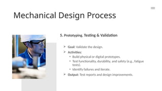
5.Prototyping, Testing & Validation
Goal: Validate the design.
Activities:
• Build physical or digital prototypes.
• Test functionality, durability, and safety (e.g., fatigue
tests).
• Identify failures and iterate.
Output: Test reports and design improvements.
13.
Mechanical Design
Process
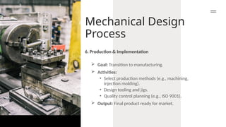
Goal:Transition to manufacturing.
Activities:
• Select production methods (e.g., machining,
injection molding).
• Design tooling and jigs.
• Quality control planning (e.g., ISO 9001).
Output: Final product ready for market.
6. Production & Implementation
14.
Mechanical Design
Process
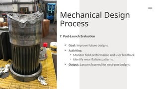
Goal:Improve future designs.
Activities:
• Monitor field performance and user feedback.
• Identify wear/failure patterns.
Output: Lessons learned for next-gen designs.
7. Post-Launch Evaluation
15.
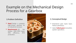
Example on theMechanical Design
Process for a Gearbox
1.Problem Definition 2. Conceptual Design
Need: Design a compact,
high-torque gearbox for
an industrial conveyor.
Requirements: 50 Nm
torque, 1000 RPM input,
90% efficiency, IP54
protection.
Brainstorm gear types (spur,
helical, planetary).
Select helical gears (smoother,
quieter operation).
16.
Example on theMechanical Design
Process for a Gearbox
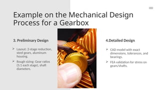
3. Preliminary Design 4.Detailed Design
Layout: 2-stage reduction,
steel gears, aluminum
housing.
Rough sizing: Gear ratios
(5:1 each stage), shaft
diameters.
CAD model with exact
dimensions, tolerances, and
bearings.
FEA validation for stress on
gears/shafts.
17.
Example on theMechanical Design
Process for a Gearbox
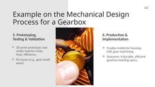
5. Prototyping,
Testing & Validation
6. Production &
Implementation
3D-print prototype; test
under load for noise,
heat, efficiency.
Fix issues (e.g., gear tooth
wear).
Finalize molds for housing,
CNC gear machining.
Outcome: A durable, efficient
gearbox meeting specs..
18.
Tools & Technologiesin Modern
Design
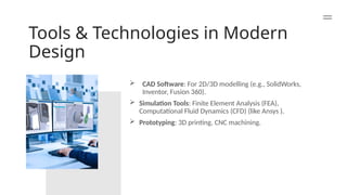
CAD Software: For 2D/3D modelling (e.g., SolidWorks,
Inventor, Fusion 360).
Simulation Tools: Finite Element Analysis (FEA),
Computational Fluid Dynamics (CFD) (like Ansys ).
Prototyping: 3D printing, CNC machining.