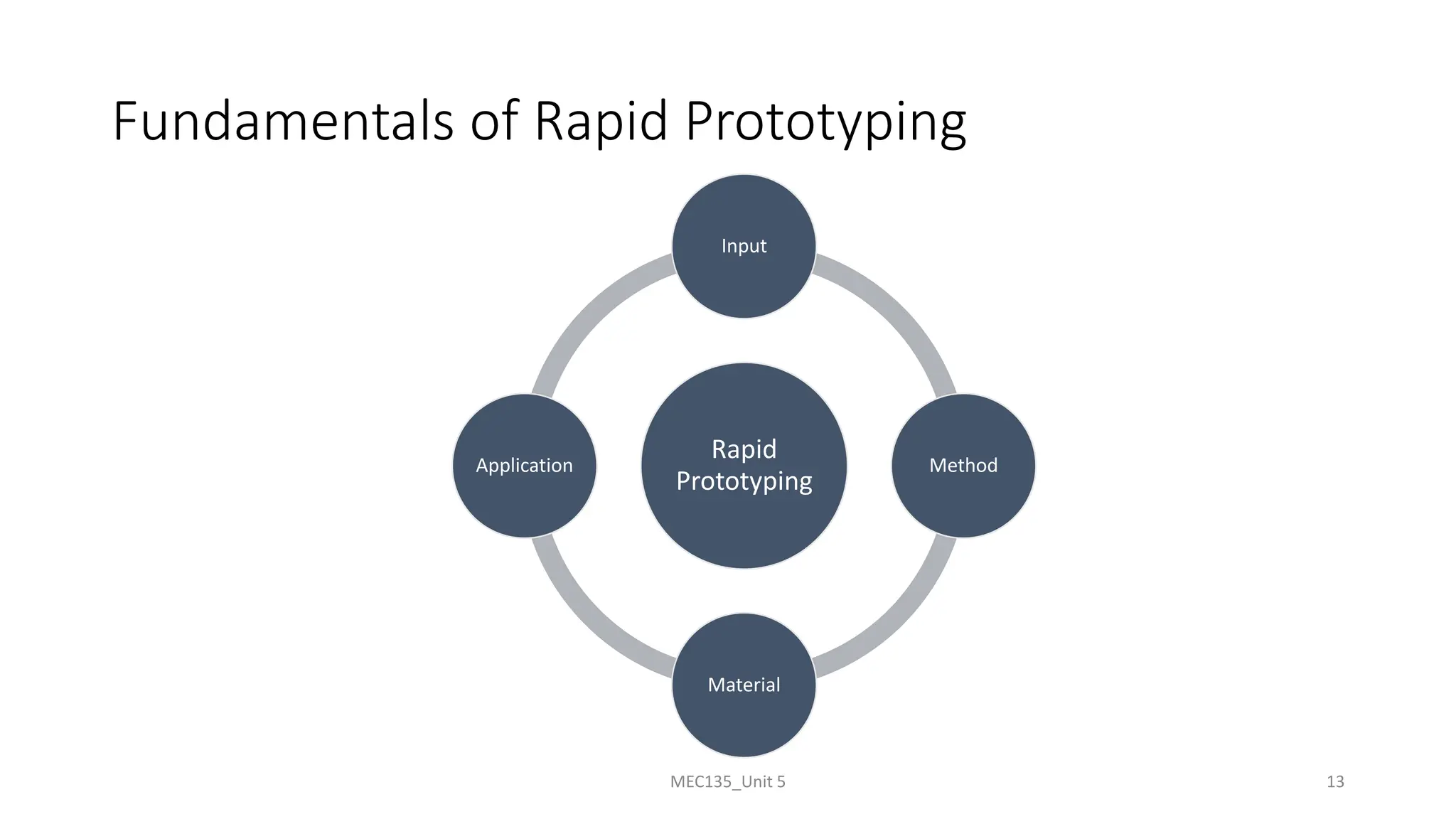
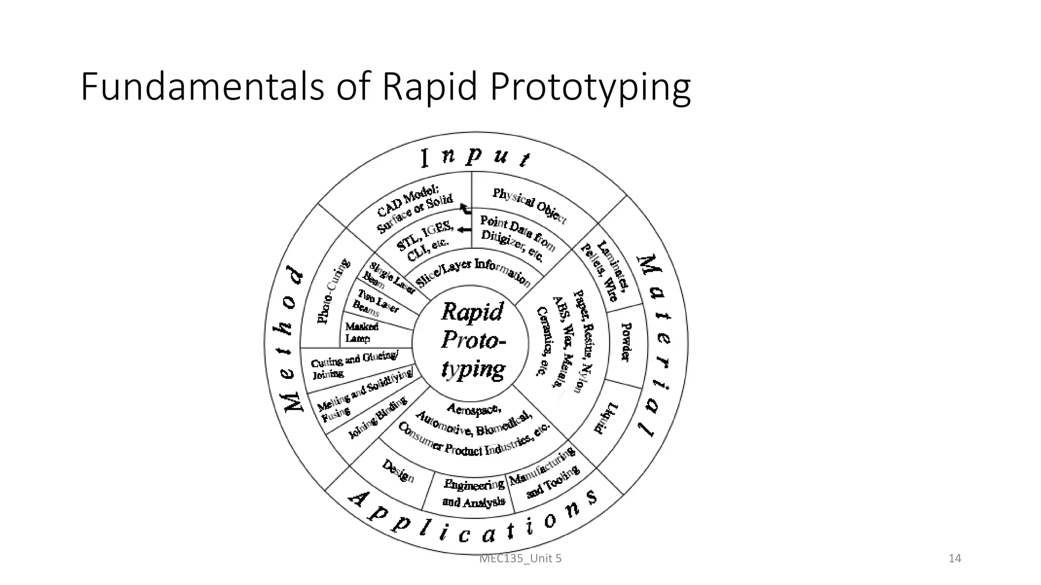
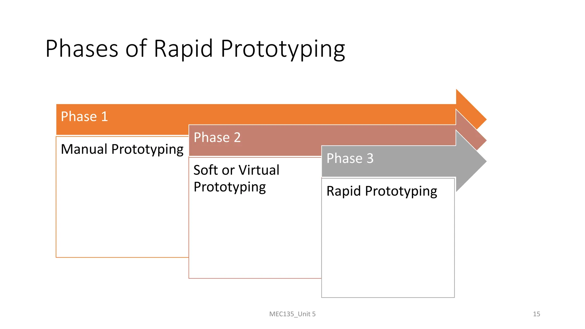
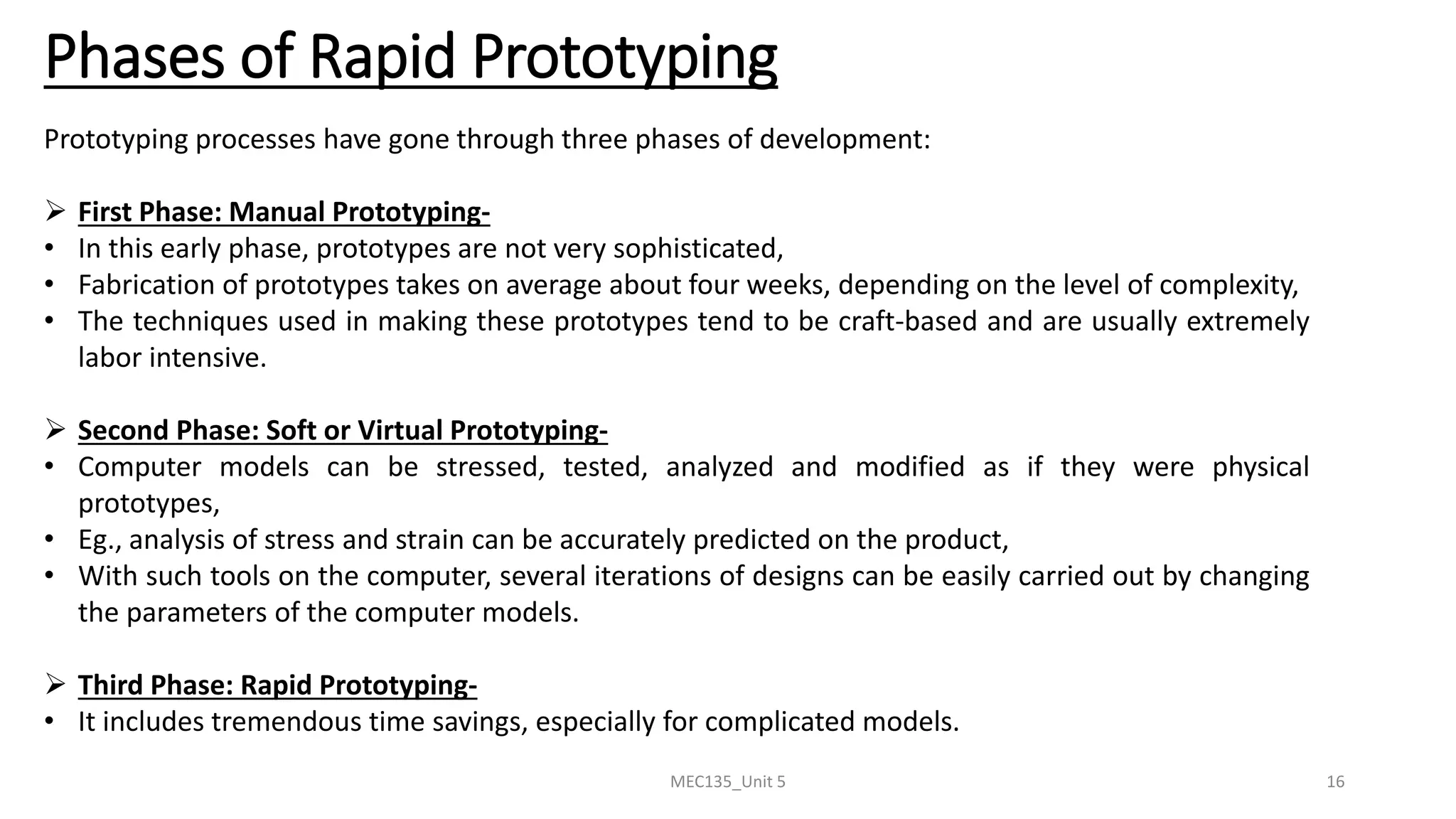
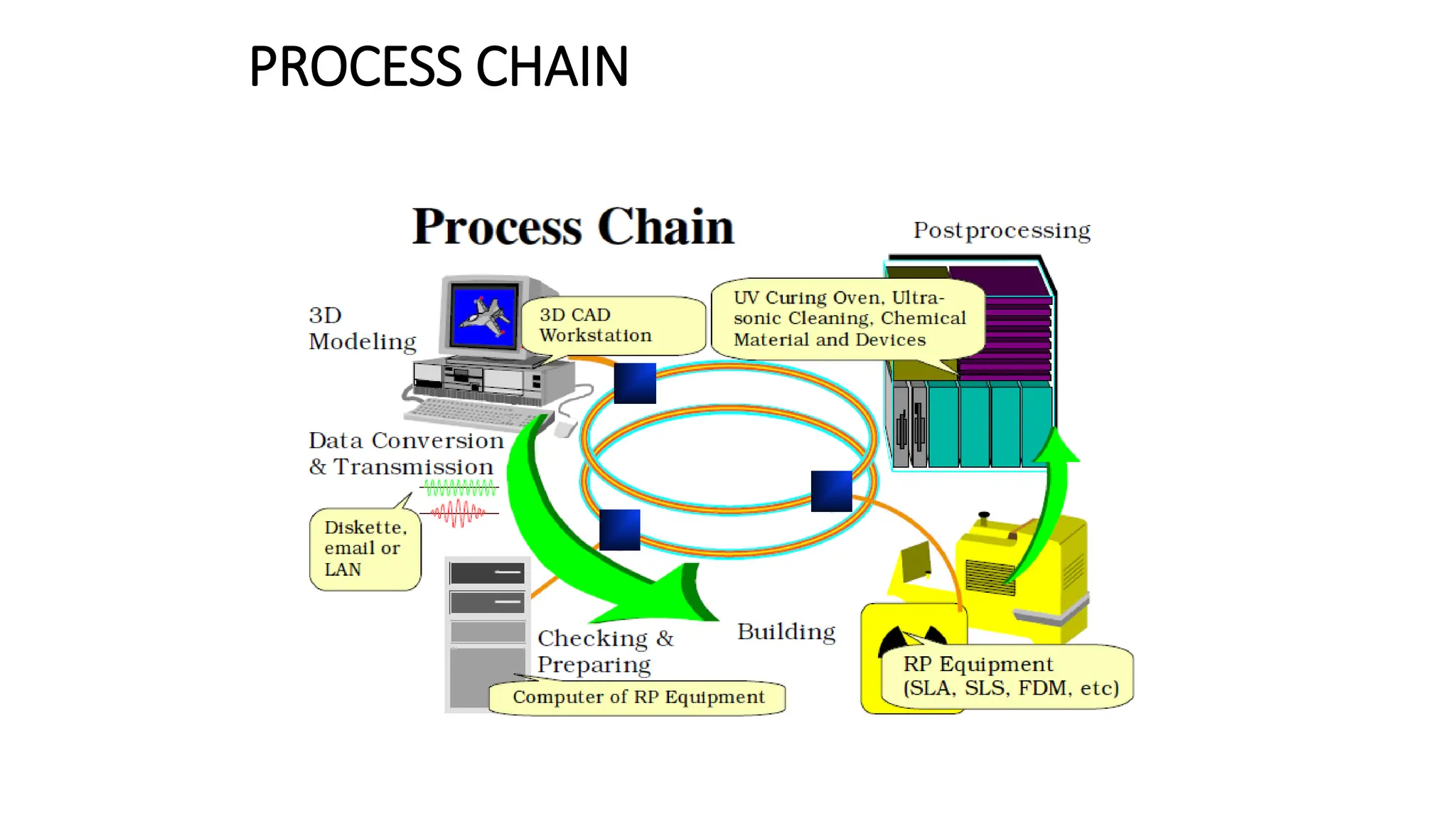
Unit 5
Introduction to Digital Fabrication
Content
1. Need of digital manufacturing
2. Prototype
3. Types and roles of prototypes
4. Rapid prototyping (RPT)
5. Phases of RPT
6. Fundamentals of RPT and Advantages
MEC135_Unit 5 2
Digital Fabrication
• Digital fabrication is a design and manufacturing workflow where digital data directly drives
manufacturing equipment to form various part geometries. For example 3d printing.
• This data most often comes from CAD (computer-aided design), which is then transferred to CAM
(computer-aided manufacturing) software.
• The output of CAM software is data that directs a specific additive and subtractive manufacturing
tool, such as a 3D printer or CNC milling machine.
MEC135_Unit 5 3
Need of digital manufacturing
• Keep it in-house – With a 3D printer and the right software, you can produce small batches of
products on your own premises without the need for external vendors
• Easy to test – Have an idea? With digital fabrication, you can bring it to life and see if it’s feasible.
It helps you gain valuable insight into your customer needs, the marketplace and anything else
that can spell the difference between success and failure
• Save money – Because you’re only making prototypes or small batches of a product, you won’t
need much storage space. You can also save money on materials by using lower-grade supplies or
even recycled plastic
• Save time – Digital fabrication accelerates the process of product development as you can create
prototypes much more quickly than traditional manufacturing methods, with no need to
outsource
• Spot errors early – Engineers like digital fabrication because it helps them spot any issues that
exist within days rather than months
MEC135_Unit 5 4
What is prototype
• A prototype is the first or original example of something that has
been or will be copied or developed. It is a model of preliminary
version
• An approximation of a product or its components in some form for a
definite purpose in its implementation
MEC135_Unit 5 5
Types of prototypes
MEC135_Unit 5 6
Implementation of the prototype
From the entire product Components
MEC135_Unit 5 7
Form of the prototype
virtual prototype physical prototype
MEC135_Unit 5 8
Roles of the Prototypes
Experimentation and Learning
Testing and Proofing
Communication and Interaction
Synthesis and Integration
Scheduling and Makers
MEC135_Unit 5 9
Roles of the Prototypes
Experimentation and Learning
Testing and Proofing
Communication and Interaction
Synthesis and Integration
Scheduling and Makers
MEC135_Unit 5 10
The roles of prototypes in the product development process are shown in Figure:
• Experimentation and Learning- Prototypes can be used to help the thinking,
planning, experimenting and learning processes whilst designing the product.
• Testing and Proofing- Eg., in the early design of folding reading glasses for the
elderly, concepts and ideas of folding mechanism can be tested by building
rough physical prototypes,
• Communication and Interaction- Protypes not just convey the information
within the product development team, but also to management and clients,
• Synthesis and Integration- A prototype can also be used to synthesize the
entire product concept by bringing the various components and sub-assemblies
together to ensure that they will work together,
• Scheduling and Makers- Prototyping helps in the scheduling of the product
development process and is usually used as markers for the end or start of the
various phases of the development effort.
MEC135_Unit 5 11
Rapid Prototyping
• Rapid prototyping is a additive manufacturing process, that
works on the basic principle of producing a 3D part by
building and stacking 2D layers together,
• Most common types of Rapid Prototyping systems are:
(a) SLA – Stereolithography,
(b) SLS – Selective Laser Sintering,
(c) LOM – Laminated Object Manufacturing,
(d) FDM – Fused Deposition Modeling
• Although these are different techniques, but their basic
principles are same.
MEC135_Unit 5 12
Rapid Prototyping
• Fabricate the model
Building the model layer by layer
Forming a 3D model by solidification of liquid/ powder
• Removing support structure and cleaning
After building, drain out extra material,
Cut out the prototype,
Cut out unnecessary support material
• Post Processing
Includes surface finishing and other processes
Fundamentals of Rapid Prototyping
Rapid
Prototyping
Input
Method
Material
Application
MEC135_Unit 5 13
Fundamentals of Rapid Prototyping
MEC135_Unit 5 14
Phases of Rapid Prototyping
Phase 1
Manual Prototyping
Phase 2
Soft or Virtual
Prototyping
Phase 3
Rapid Prototyping
MEC135_Unit 5 15
MEC135_Unit 5 16
Phases of Rapid Prototyping
Prototyping processes have gone through three phases of development:
➢ First Phase: Manual Prototyping-
• In this early phase, prototypes are not very sophisticated,
• Fabrication of prototypes takes on average about four weeks, depending on the level of complexity,
• The techniques used in making these prototypes tend to be craft-based and are usually extremely
labor intensive.
➢ Second Phase: Soft or Virtual Prototyping-
• Computer models can be stressed, tested, analyzed and modified as if they were physical
prototypes,
• Eg., analysis of stress and strain can be accurately predicted on the product,
• With such tools on the computer, several iterations of designs can be easily carried out by changing
the parameters of the computer models.
➢ Third Phase: Rapid Prototyping-
• It includes tremendous time savings, especially for complicated models.
Classification of Rapid Prototyping
• Liquid-Based
• Solid-Based
• Powder-Based
Classification of Rapid Prototyping
Liquid-Based
• Liquid-based RP systems have the initial form of its
material in liquid state.
• Through a process commonly known as curing, the liquid
is converted into the solid state.
1. 3D Systems’ Stereolithography Apparatus (SLA)
2. Cubital’s Solid Ground Curing (SGC)
3. Sony’s Solid Creation System (SCS)
Classification of Rapid Prototyping
Solid-Based
• Except for powder, solid-based RP systems are meant to
encompass all forms of material in the solid state.
• In this context, the solid form can include the shape in the
form of a wire, a roll, laminates and pellets.
1. Kira Corporation’s Paper Lamination Technology (PLT)
2. 3D Systems’ Multi-Jet Modeling System (MJM)
3. Solidscape’s ModelMaker and PatternMaster
Classification of Rapid Prototyping
Powder-Based
• In a strict sense, powder is by-and-large in the solid state.
• However, it is intentionally created as a category outside
the solid-based RP systems to mean powder in grain-like
form.
1. Z Corporation’s Three-Dimensional Printing (3DP)
2. 3D Systems’s Selective Laser Sintering (SLS)
3. EOS’s EOSINT Systems
PROCESS CHAIN
PROCESS CHAIN
• There are a total of five steps in the chain and these are
1. 3D modeling,
2. data conversion and transmission,
3. checking and preparing,
4. building
5. and post-processing.
• Depending on the quality of the model and part in Steps
3 and 5 respectively, the process may be iterated until a
satisfactory model or part is achieved.
3D MODELLING
• Advanced 3D CAD modeling is a general prerequisite in RP
processes
• It also involved FEM analysis, detail design and drafting, planning
for manufacturing,
• Special care to be taken for orientation of part, need for supports,
difficult-to-build part structure such as thin walls, small slots or
holes and overhanging elements.
• under-specifying parameters to the RP systems, resulting in poor
performance and non-optimal utilization of the system.
DATA CONVERSION AND TRANSMISSION
• The solid or surface model to be built is next converted into a
format dubbed the STL file format.
• The STL file format approximates the surfaces of the model using
tiny triangles.
• Highly curved surfaces must employ many more triangles, which
mean that STL files for curved parts can be very large.
STL FILE
DATA CONVERSION AND TRANSMISSION
• Almost, if not all, major CAD/CAM vendors supply the CAD-STL
interface.
• This conversion step is probably the simplest and shortest of the
entire process chain.
• For a highly complex model coupled with an extremely low
performance workstation or PC, the conversion can take several
hours.
• Otherwise, the conversion to STL file should take only several
minutes.
• Where necessary, supports are also converted to a separate STL
file.
CHECKING AND PREPARING
• This process of manual repair is very tedious and time consuming
• The CAD model errors are corrected by human operators assisted
by specialized software such as MAGICS
• Once the STL files are verified to be error-free, the system slices
the model into cross-sections.
• Each output file is sliced into cross-sections, between 0.12 mm
(minimum) to 0.50 mm (maximum) in thickness.
• The model is sliced into the thinnest layer as they have to be very
accurate.
• The supports can be created using coarser settings
BUILDING
• For most RP systems, this step is fully automated.
• Thus, it is usual for operators to leave the machine on to build a
part overnight.
• The building process may take up to several hours to build
depending on the size and number of parts required.
POSTPROCESSING
• The final task in the process chain is the post-processing task.
• At this stage, generally some manual operations are necessary.
• As a result, the danger of damaging a part is particularly high.
• the operator for this last process step has a high responsibility for
the successful process realization.
Advantages of Rapid Prototyping
Advantages
of
Rapid
Prototyping Direct Benefits
Benefits to Product
Designers
Benefits to tooling and
Manufacturing Engg
Indirect Benefits
Benefits to Marketers
Benefits to Consumers
MEC135_Unit 5 30
MEC135_Unit 5 31
Advantages of Rapid Prototyping
➢ Design Applications-
• Designers can confirm their designs by building a real physical model in minimum time using RP,
Design Benefits-
• Reduced lead times to produce prototypes,
• Improved ability to visualize the part geometry,
• Early detection of design errors,
➢ Engineering Analysis and Design-
• Comparison of different shapes and styles to determine aesthetic appeal,
• Stress analysis of physical models,
• Fabrication of pre-production parts for process planning and tool design
MEC135_Unit 5 32
Advantages of Rapid Prototyping
• Process is Fast and accurate,
• Superior surface finish,
• Separate materials can be used for components and supports,
• No need to design jigs and fixtures,
• No need of moulds and other tools,
• Harder materials can be easily used,
• Minimum materials wastage,
• Reduces product development cycle time considerably
Thanks
MEC135_Unit 5 33

Introduction To Digital Fabrication notes

  • 1.
    Unit 5 Introduction toDigital Fabrication
  • 2.
    Content 1. Need ofdigital manufacturing 2. Prototype 3. Types and roles of prototypes 4. Rapid prototyping (RPT) 5. Phases of RPT 6. Fundamentals of RPT and Advantages MEC135_Unit 5 2
  • 3.
    Digital Fabrication • Digitalfabrication is a design and manufacturing workflow where digital data directly drives manufacturing equipment to form various part geometries. For example 3d printing. • This data most often comes from CAD (computer-aided design), which is then transferred to CAM (computer-aided manufacturing) software. • The output of CAM software is data that directs a specific additive and subtractive manufacturing tool, such as a 3D printer or CNC milling machine. MEC135_Unit 5 3
  • 4.
    Need of digitalmanufacturing • Keep it in-house – With a 3D printer and the right software, you can produce small batches of products on your own premises without the need for external vendors • Easy to test – Have an idea? With digital fabrication, you can bring it to life and see if it’s feasible. It helps you gain valuable insight into your customer needs, the marketplace and anything else that can spell the difference between success and failure • Save money – Because you’re only making prototypes or small batches of a product, you won’t need much storage space. You can also save money on materials by using lower-grade supplies or even recycled plastic • Save time – Digital fabrication accelerates the process of product development as you can create prototypes much more quickly than traditional manufacturing methods, with no need to outsource • Spot errors early – Engineers like digital fabrication because it helps them spot any issues that exist within days rather than months MEC135_Unit 5 4
  • 5.
    What is prototype •A prototype is the first or original example of something that has been or will be copied or developed. It is a model of preliminary version • An approximation of a product or its components in some form for a definite purpose in its implementation MEC135_Unit 5 5
  • 6.
  • 7.
    Implementation of theprototype From the entire product Components MEC135_Unit 5 7
  • 8.
    Form of theprototype virtual prototype physical prototype MEC135_Unit 5 8
  • 9.
    Roles of thePrototypes Experimentation and Learning Testing and Proofing Communication and Interaction Synthesis and Integration Scheduling and Makers MEC135_Unit 5 9
  • 10.
    Roles of thePrototypes Experimentation and Learning Testing and Proofing Communication and Interaction Synthesis and Integration Scheduling and Makers MEC135_Unit 5 10 The roles of prototypes in the product development process are shown in Figure: • Experimentation and Learning- Prototypes can be used to help the thinking, planning, experimenting and learning processes whilst designing the product. • Testing and Proofing- Eg., in the early design of folding reading glasses for the elderly, concepts and ideas of folding mechanism can be tested by building rough physical prototypes, • Communication and Interaction- Protypes not just convey the information within the product development team, but also to management and clients, • Synthesis and Integration- A prototype can also be used to synthesize the entire product concept by bringing the various components and sub-assemblies together to ensure that they will work together, • Scheduling and Makers- Prototyping helps in the scheduling of the product development process and is usually used as markers for the end or start of the various phases of the development effort.
  • 11.
    MEC135_Unit 5 11 RapidPrototyping • Rapid prototyping is a additive manufacturing process, that works on the basic principle of producing a 3D part by building and stacking 2D layers together, • Most common types of Rapid Prototyping systems are: (a) SLA – Stereolithography, (b) SLS – Selective Laser Sintering, (c) LOM – Laminated Object Manufacturing, (d) FDM – Fused Deposition Modeling • Although these are different techniques, but their basic principles are same.
  • 12.
    MEC135_Unit 5 12 RapidPrototyping • Fabricate the model Building the model layer by layer Forming a 3D model by solidification of liquid/ powder • Removing support structure and cleaning After building, drain out extra material, Cut out the prototype, Cut out unnecessary support material • Post Processing Includes surface finishing and other processes
  • 13.
    Fundamentals of RapidPrototyping Rapid Prototyping Input Method Material Application MEC135_Unit 5 13
  • 14.
    Fundamentals of RapidPrototyping MEC135_Unit 5 14
  • 15.
    Phases of RapidPrototyping Phase 1 Manual Prototyping Phase 2 Soft or Virtual Prototyping Phase 3 Rapid Prototyping MEC135_Unit 5 15
  • 16.
    MEC135_Unit 5 16 Phasesof Rapid Prototyping Prototyping processes have gone through three phases of development: ➢ First Phase: Manual Prototyping- • In this early phase, prototypes are not very sophisticated, • Fabrication of prototypes takes on average about four weeks, depending on the level of complexity, • The techniques used in making these prototypes tend to be craft-based and are usually extremely labor intensive. ➢ Second Phase: Soft or Virtual Prototyping- • Computer models can be stressed, tested, analyzed and modified as if they were physical prototypes, • Eg., analysis of stress and strain can be accurately predicted on the product, • With such tools on the computer, several iterations of designs can be easily carried out by changing the parameters of the computer models. ➢ Third Phase: Rapid Prototyping- • It includes tremendous time savings, especially for complicated models.
  • 17.
    Classification of RapidPrototyping • Liquid-Based • Solid-Based • Powder-Based
  • 18.
    Classification of RapidPrototyping Liquid-Based • Liquid-based RP systems have the initial form of its material in liquid state. • Through a process commonly known as curing, the liquid is converted into the solid state. 1. 3D Systems’ Stereolithography Apparatus (SLA) 2. Cubital’s Solid Ground Curing (SGC) 3. Sony’s Solid Creation System (SCS)
  • 19.
    Classification of RapidPrototyping Solid-Based • Except for powder, solid-based RP systems are meant to encompass all forms of material in the solid state. • In this context, the solid form can include the shape in the form of a wire, a roll, laminates and pellets. 1. Kira Corporation’s Paper Lamination Technology (PLT) 2. 3D Systems’ Multi-Jet Modeling System (MJM) 3. Solidscape’s ModelMaker and PatternMaster
  • 20.
    Classification of RapidPrototyping Powder-Based • In a strict sense, powder is by-and-large in the solid state. • However, it is intentionally created as a category outside the solid-based RP systems to mean powder in grain-like form. 1. Z Corporation’s Three-Dimensional Printing (3DP) 2. 3D Systems’s Selective Laser Sintering (SLS) 3. EOS’s EOSINT Systems
  • 21.
  • 22.
    PROCESS CHAIN • Thereare a total of five steps in the chain and these are 1. 3D modeling, 2. data conversion and transmission, 3. checking and preparing, 4. building 5. and post-processing. • Depending on the quality of the model and part in Steps 3 and 5 respectively, the process may be iterated until a satisfactory model or part is achieved.
  • 23.
    3D MODELLING • Advanced3D CAD modeling is a general prerequisite in RP processes • It also involved FEM analysis, detail design and drafting, planning for manufacturing, • Special care to be taken for orientation of part, need for supports, difficult-to-build part structure such as thin walls, small slots or holes and overhanging elements. • under-specifying parameters to the RP systems, resulting in poor performance and non-optimal utilization of the system.
  • 24.
    DATA CONVERSION ANDTRANSMISSION • The solid or surface model to be built is next converted into a format dubbed the STL file format. • The STL file format approximates the surfaces of the model using tiny triangles. • Highly curved surfaces must employ many more triangles, which mean that STL files for curved parts can be very large.
  • 25.
  • 26.
    DATA CONVERSION ANDTRANSMISSION • Almost, if not all, major CAD/CAM vendors supply the CAD-STL interface. • This conversion step is probably the simplest and shortest of the entire process chain. • For a highly complex model coupled with an extremely low performance workstation or PC, the conversion can take several hours. • Otherwise, the conversion to STL file should take only several minutes. • Where necessary, supports are also converted to a separate STL file.
  • 27.
    CHECKING AND PREPARING •This process of manual repair is very tedious and time consuming • The CAD model errors are corrected by human operators assisted by specialized software such as MAGICS • Once the STL files are verified to be error-free, the system slices the model into cross-sections. • Each output file is sliced into cross-sections, between 0.12 mm (minimum) to 0.50 mm (maximum) in thickness. • The model is sliced into the thinnest layer as they have to be very accurate. • The supports can be created using coarser settings
  • 28.
    BUILDING • For mostRP systems, this step is fully automated. • Thus, it is usual for operators to leave the machine on to build a part overnight. • The building process may take up to several hours to build depending on the size and number of parts required.
  • 29.
    POSTPROCESSING • The finaltask in the process chain is the post-processing task. • At this stage, generally some manual operations are necessary. • As a result, the danger of damaging a part is particularly high. • the operator for this last process step has a high responsibility for the successful process realization.
  • 30.
    Advantages of RapidPrototyping Advantages of Rapid Prototyping Direct Benefits Benefits to Product Designers Benefits to tooling and Manufacturing Engg Indirect Benefits Benefits to Marketers Benefits to Consumers MEC135_Unit 5 30
  • 31.
    MEC135_Unit 5 31 Advantagesof Rapid Prototyping ➢ Design Applications- • Designers can confirm their designs by building a real physical model in minimum time using RP, Design Benefits- • Reduced lead times to produce prototypes, • Improved ability to visualize the part geometry, • Early detection of design errors, ➢ Engineering Analysis and Design- • Comparison of different shapes and styles to determine aesthetic appeal, • Stress analysis of physical models, • Fabrication of pre-production parts for process planning and tool design
  • 32.
    MEC135_Unit 5 32 Advantagesof Rapid Prototyping • Process is Fast and accurate, • Superior surface finish, • Separate materials can be used for components and supports, • No need to design jigs and fixtures, • No need of moulds and other tools, • Harder materials can be easily used, • Minimum materials wastage, • Reduces product development cycle time considerably
  • 33.