1. Radical RXC Chassis Report
Overview- The tubular space frame for Radical RXC was designed keeping in mind to achieve
high torsional stiffness with minimum weight to get an overall better performance of the
race car.
Brief Literature review- While designing space frame for Radical RXC rule of triangulation
was kept in mind as it allows only tensile and compressive stresses to be transmitted
through tubes and reducing the possibility of shear forces which is undesirable for a space
frame structure.
The material used in designing process is AISI 1020 steel( cold rolled) having Ultimate
tensile strength – 420 Mpa and yield strength – 350Mpa which is desirable for space frame
chassis subjected to torsional and bending forces.
A space frame is strong because of the inherent rigidity of the triangle; flexing loads
(bending moments) are transmitted as tension and compression loads along the length of
each strut. Also it was decided to keep slenderness ratio (L/K) of each tube to be greater
than 10.The wheelbase of the car was assumed to be 1770 mm and front and rear track
width as 820 mm. The thickness of the tubes that were used was:
Roll Hoops – 40 x 2.5 mm
Side Impact and front bulkhead – 40 x 2 mm
Triangulation tubes – 25 x 2 mm
*These tube dimensions were decided after having relative knowledge of tube dimensions of FSAE
space frames.
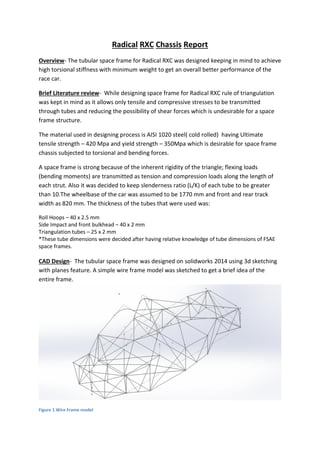
CAD Design- The tubular space frame was designed on solidworks 2014 using 3d sketching
with planes feature. A simple wire frame model was sketched to get a brief idea of the
entire frame.
Figure 1 Wire Frame model
2. Weldments of required dimensions were added to the wire model and were profiled using trim and
extend feature of solidworks.
Figure 2 Frame CAD model
Finite element analysis(FEA)- The FEA of this space frame was done using solidworks 2014
simulation tool. Simple torsional test was performed on the frame by applying equal and opposite
torques on front wheel centres. An equal and opposite force of 500N was applied on front wheel
centres keeping the rear hard points constrained.
Figure 3 Static displacement plot
3. Figure 4 Static Stress plot( Von Mises stress)
Torsional stiffness calculation:
F : Force applied
Τ : Applied Torque
d : Distance between wheel centres
δ : Deflection of wheel centre
φ : Angular deflection of wheel centre
d= 820mm = 0.82m
For left wheel:
δL = 0.1339mm
φL= (Deflection ofleft wheel centre)/(Distance of left wheel centre from vehicle centreline)
= (δL )/(d/2)
= 0.1339mm⁄410 mm = 3.26 x 10^-4 rad = 0.0186 degree
For right wheel:
δR = 0.1336 mm
φR = (δR )/(d/2) = 0.1336⁄410mm= 3.26 x 10^-4 rad = 0.0186
φav = (φL + φR)/2 = 0.0186 °
4. Torque applied, Τ = F x d = 500 x 0.82 = 410 N-m
Torsional Stiffness = Τ / φav = 410 N-m / 0.0186 ° = 22,043 N-m/deg.
Results-
Maximum deflections of 0.1339mm found in the frame at nodes where opposite forces
were applied. A von Mises stress plot was also plotted as shown in the figure above and
maximum stress was found to be 1.06 x 10⁷ N/m^2 which was found to be satisfactory
considering the design requirements.
The torsional stiffness of the frame as calculated is 22,043 N-m/deg which is very much
desirable for a high performance sports car.
Suggested Improvements-
1. Choosing appropriate target value of torsional stiffness. The torsional rigidity of
frame currently is very high which should be in range of 17,000 to 21,000N-m/deg.
2. Reduction in weight by reducing tube dimensions of proper UTM testing, this will
also reduce torsional stiffness and increase overall performance of the sports car.
3. Some tubes in frame have slenderness ratio < 10 which can cause buckling which is
not desirable in a high performance sports car.
4. Ergonomic factors were not considered which also plays a vital role and affects
performance of a sports car.
5. Having properly constructed hard points could have been beneficial in designing
process of the space frame keeping aesthetics under consideration.
Conclusion-
The overall performance can be considered satisfactory but can be increased by performing
more weight saving operations. As assembly of different components were not taken into
consideration, the stiffest parts of the frame could not be determined.