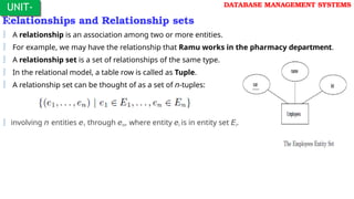
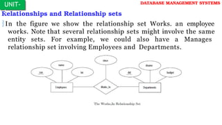
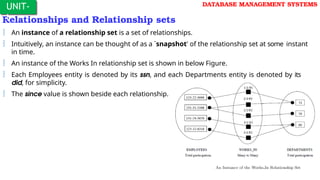
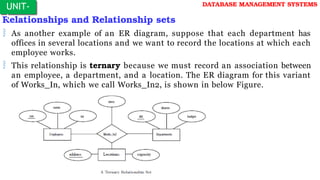
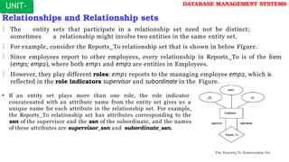
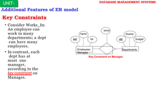
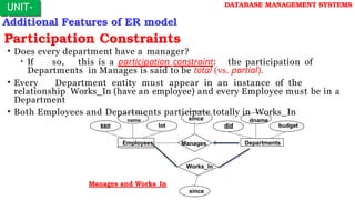
Department of CSE(IOT)
Prepared By:
KRISHNAA
Asst. Professor-CSE(IOT)
III Year B.Tech. ISemester
Regulation: R22
Subject: DATABASE MANAGEMENT SYSTEMS
SYLLABUS:
Database System Applications: A historical perspective, file system
Vs. database system, The data model, Levels abstraction in DBMS,
Data Independence, Structure of a DBMS.
Introduction To Database Design: Database design and ER Diagrams,
Entities, attributes and entity sets, relationships and relationship sets,
additional features of ER model, concept design with the ER Model.
DATABASE MANAGEMENT SYSTEMS
UNIT-I
DATABASE MANAGEMENT SYSTEMS
 Introduction:
 Data: The collection of raw facts is called data.
 Information: The processed data is called information. It is derived from the
data.
 Database: Database is a collection of interrelated relevant data stored together to
be used by multiple applications or to serve an enterprise.
 A database-management system (DBMS) is a collection of interrelated
data and a set of programs to access those data.
 The primary goal of a DBMS is to provide a way to store and retrieve
database information that is both convenient and efficient.
UNIT-
I
DATABASE MANAGEMENT SYSTEMS
 Introduction: DBMS AND RDBMS:
 DBMS: Database + Management System
 DBMS is a kind of software used to create the database and manage the
databases.
 In DBMS data is stored as a file.
 Examples: MS-ACCESS, dBase etc..
 RDBMS: Relational Database Systems
 Used to create and manage the relational databases.
 In RDBMS data is stored as tables.
 Examples: Oracle, SQL Server, MySQL,IBM DB2,postgreSQL, MongoDB, etc..
 Note: Dr.Edger.F.Codd(E.F Codd) is known as Father of DBMS.
UNIT-
I
Database System Applications
 Databases are widely used. Here are some
representative applications:
Enterprise Information
Sales: For customer, product, and purchase information.
Accounting: For payments, receipts, account balances, assets and other accounting
information.
 Human resources: For information about employees, salaries, payroll
taxes, and
benefits, and for generation of paychecks.
Manufacturing: For management of the supply chain and for tracking production of
items in factories, inventories of items in warehouses and stores, and orders for items.
Online retailers: For sales data noted above plus online order tracking, generation of
recommendation lists, and maintenance of online product evaluations.
UNIT-
I
DATABASE MANAGEMENT SYSTEMS
Database System Applications
Banking and Finance
Banking: For customer information, accounts, loans, and banking
transactions.
Credit card transactions: For purchases on credit cards and
generation of monthly statements.
Finance: For storing information about holdings, sales, and
purchases of financial instruments such as stocks and bonds; also
for storing real-time market data to enable online trading by
customers and automated trading by the firm.
UNIT-
I
DATABASE MANAGEMENT SYSTEMS
Database System Applications
Universities: For student information, course registrations, and
grades (in addition to standard enterprise information such as
human resources and accounting).
Airlines: For reservations and schedule information. Airlines were
among the first to use databases in a geographically distributed
manner.
Telecommunication: For keeping records of calls made, generating
monthly bills, maintaining balances on prepaid calling cards, and
storing information about the communication networks.
UNIT-
I
DATABASE MANAGEMENT SYSTEMS
Database System Applications (In Anotherway)
 Database Applications:
 Banking: all transactions
 Airlines: reservations, schedules
 Universities: registration, grades
 Sales: customers, products, purchases
 Online retailers: order tracking, customized recommendations
 Manufacturing: production, inventory, orders, supply chain
 Human resources: employee records, salaries, tax
deductions
 Databases touch all aspects of our lives
UNIT-
I
DATABASE MANAGEMENT SYSTEMS
History of Database Systems
 1950s and early 1960s:
 Data processing
using storage
magnetic tapes for
 Tapes provide only sequential access
 Punched cards for input
 Late 1960s and 1970s:
 Hard disks allow direct
access to data
 Network and
hierarchical
data
models in
widespread use
 Ted Codd defines the
relational data model
 Would win the ACM
Turing Award for this
work
 IBM Research begins
UNIT-
I
DATABASE MANAGEMENT SYSTEMS
 1980s:
 Research relational
commercial systems
prototypes evolve into
 SQL becomes industrial standard
 Parallel and distributed database systems
 Object-oriented database systems
 1990s:
 Large decision support and
applications
 Large multi-terabyte data warehouses
 Emergence of Web commerce
 2000s:
 XML and XQuery standards
 Automated database administration
data-mining
File System Vs Database System.
 In the early days, database applications were built directly on top of file
systems
Drawbacks of using file systems to store data:
 There are seven problem are there in the file systems and that’s why file system are not suitable for organizations for efficient storing
and retrieving purpose.
 Data redundancy and inconsistency:
1. Different programmers
2. Different structures .
3. Different different programming Languages .
4. Duplication-Redundancy
5. Higher Storage and Access cost
Each file stored in different location ,one may be in C drive or D drive or e, one file may be one directory or exssting directory in such a
siltation which are duplicate a Records
Multiple file formats, duplication of information in different files
UNIT-
I
DATABASE MANAGEMENT SYSTEMS
 Difficulty in accessing data: For example
 Find out all student who resides in a particular city.
 Find out all student who gained 25 credits
 List of both
 File systems are not convenient and efficient
 More responsive data-retrieval system is needed.
 Note: DBMS CAN DO ALL THESE THINGS
Need to write a new program to carry out each new task
Ex: when new query is asked
 Data isolation — multiple files and formats, Data are scattered in different files. Files may be in different location ,Data
Isolation is difficult
 Integrity problems:
Integrity constraints (e.g. account balance > 0) become “buried” in program code rather than
being stated explicitly
Hard to add new constraints or change existing ones
File System Vs Database System.
Drawbacks of using file systems (cont.)
Atomicity problem
1.Difficulty to ensure atomicity in a conventional file processing system 2.Any system is subject to failure 3.Restoration of data
Failures may leave database in an inconsistent state with partial updates carried out
Example: Transfer of funds from one account to another should either complete or
not happen at all
Concurrent access by Anomalies: 1.concurrency is always good
 concurrent access anomalies are there in file system but in DBMS there really good
Uncontrolled concurrent accesses can lead to inconsistencies
 Example: Two people reading a balance and updating it at the same time
Security problems
 1.Data access 2.Authentication and Authorization 3.Finance person should not access Academic
records
Database systems offer solutions to all the above problems
UNIT-
I
DATABASE MANAGEMENT SYSTEMS
View of Data
 A database system is a collection of interrelated data and a set of programs
that allow users to access and modify these data.
 A major purpose of a database system is to provide users with an abstract
view of the data.
 That is, the system hides certain details of how the data are stored and
maintained.
Data Abstraction
Instances and Schemas
Data Models
UNIT-
I
DATABASE MANAGEMENT SYSTEMS
View of Data- Data Abstraction
Levels of Abstraction
 Physical(Lowest) level: describes
how a record (e.g., customer) is
stored.
 Logical (Next-Higher) level: describes data stored in database, and the
relationships among the data. The next-higher level of abstraction describes
what data are stored in the database, and what relationships exist among
those data.
type customer = record
customer_id : string;
customer_name : string;
customer_street : string;
customer_city : integer;
end;
 View(Highest) level: application programs hide details of data types. Views
UNIT-
I
DATABASE MANAGEMENT SYSTEMS
View of Data- Data Abstraction
Levels of Abstraction
UNIT-
I
DATABASE MANAGEMENT SYSTEMS
View of Data- Instances and Schemas
 The collection of information stored in the database at a
particular moment is called an instance of the database.
 The overall design of the database is called the database schema.
 Schemas are changed infrequently, if at all.
 The concept of database schemas and instances can be understood by
analogy to a program written in a programming language.
 A database schema corresponds to the variable declarations (along
with associated type definitions) in a program.
 Each variable has a particular value at a given instant.
 The values of the variables in a program at a point in time correspond
to an instance of a database schema.
UNIT-
I
DATABASE MANAGEMENT SYSTEMS
View of Data- Instances and Schemas
 Database systems have several schemas, partitioned according to the levels
of abstraction.
 The physical schema describes the database design at the physical level.
 the logical schema describes the database design at the logical level.
 A database may also have several schemas at the view level, sometimes called
subschemas, that describe different views of the database.
 Of these, the logical schema is by far the most important, in terms of its effect on
application programs, since programmers construct applications by using the
logical schema.
 The physical schema is hidden beneath the logical schema, and can usually be
changed easily without affecting application programs.
 Application programs are said to exhibit physical data independence if they do
not depend on the physical schema, and thus need not be rewritten if the
physical schema changes.
UNIT-
I
DATABASE MANAGEMENT SYSTEMS
View of Data- DataModels
 Underlying the structure of a database is the data model.
 A data model collection of tools for describing
 Data
 Data relationships
 Data semantics
 Data constraints
 A data model provides a way to describe the design of a database at the
physical, logical, and view levels.
 The data models can be classified into four different categories:
Relational Model
Entity-Relationship Model.
Object-Based Data Model.
Semistructured Data Model.
UNIT-
I
DATABASE MANAGEMENT SYSTEMS
View of Data- DataModels
Relational model
 The relational model uses a collection of tables to represent both data and the relationships
among those data.
 Each table has multiple columns, and each column has a unique name.
 Tables are also known as relations.
 The relational model is an example of a record-based model.
 Record-based models are so named because the database is structured in fixed-
format
records of several types.
 Each table contains records of a particular type.
 Each record type defines a fixed number of fields, or attributes.
 The columns of the table correspond to the attributes of the record type.
 The relational data model is the most widely used data model, and a vast majority of current
database systems are based on the relational model.
UNIT-
I
DATABASE MANAGEMENT SYSTEMS
View of Data- DataModels
Entity-Relationship data model (mainly for database design)
 The Entity-Relationship (E-R) data model uses a collection of basic objects, called entities,
and
relationships among these objects.
 An entity is a “thing” or “object” in the real world that is distinguishable from other objects.
 The Entity-Relationship model is widely used in database design.
Object-based data models (Object-oriented and Object-relational)
 Object-oriented programming (especially in Java, C++, or C#) has become the dominant software-
development methodology.
 This led to the development of an object-oriented data model that can be seen as extending the E-R
model with notions of encapsulation, methods (functions), and object identity.
 The object-relational data model combines features of the object-oriented data model and relational
data model.
UNIT-
I
DATABASE MANAGEMENT SYSTEMS
View of Data- DataModels
Semistructured data model (XML)
 The semistructured data model permits the specification of data where individual data items of the
same type may have different sets of attributes.
 This is in contrast to the data models mentioned earlier, where every data item of a particular type
must have the same set of attributes.
 The Extensible Markup Language (XML) is widely used to represent semistructured data.
 Other older models:
 Network model
 Hierarchical model
 Historically, the Network data model and the Hierarchical data model preceded the relational data
model.
 These models were tied closely to the underlying implementation, and complicated the task
of
modeling data.
 As a result they are used little now, except in old database code that is still in service in some places.
UNIT-
I
DATABASE MANAGEMENT SYSTEMS
Database Languages: DDL, DML
Database system provides a Data-Definition Language(DDL) to
specify the database schema and a Data-Manipulation
Language(DML) to express database queries and up dates.
In practice, the data-definition and data-manipulation languages are
not two separate languages; instead they simply form parts of a
single database language, such as the widely used SQL language.
UNIT-
I
DATABASE MANAGEMENT SYSTEMS
Database Languages:--Data-Manipulation Language(DML):
A Data-Manipulation Language (DML) is a language that enables
users to access or manipulate data as organized by the appropriate
data model. The types of access are:
oRetrieval of information stored in the database
oInsertion of new information into the database
oDeletion of information from the database
oModification of information stored in the database
UNIT-
I
DATABASE MANAGEMENT SYSTEMS
Database Languages:-- Data-Manipulation Language(DML):
There are basically two types:
 Procedural DMLs require a user to specify what data are needed and how to
get those data.
 Declarative DMLs (also referred to as nonprocedural DMLs) require a user to
specify what data are needed without specifying how to get those data.
 Declarative DMLs are usually easier to learn and use than are procedural DMLs.
However, since a user does not have to specify how to get the data, the
database system has to figure out an efficient means of accessing data.
A query is a statement requesting the retrieval of information. The
portion of a DML that involves information retrieval is called a query
language.
 Although technically incorrect, it is common practice to use the terms query
language and data-manipulation language synonymously.
UNIT-
I
DATABASE MANAGEMENT SYSTEMS
Database Languages:--Data-Definition Language(DML):
 Specification notation for defining the database schema
Example: create table account (
account-number
balance
char(10),
integer);
 DDL compiler generates a set of tables stored in a data dictionary
 Data dictionary contains metadata (i.e., data about data)
 Database schema
 Data storage and definition language
 Specifies the storage structure and access methods used
 Integrity constraints
 Domain constraints
 Referential integrity (references constraint in SQL)
 Assertions
 Authorization
UNIT-
I
DATABASE MANAGEMENT SYSTEMS
Database Access for Application Programs
UNIT-
I
DATABASE MANAGEMENT SYSTEMS
Database Users and Administrator
Database Users:
Users are differentiated by the way they
expect to interact with the system
Application programmers – computer professionals who write application
Programs (or) interact with system through DML calls
 Sophisticated users –interact with the system without writing programs (or)
form requests in a database query language
 Specialized users – sophisticated users who write specialized database
applications that do not fit into the traditional data-processing framework.
 Naïve users – unsophisticated users who interact with the system by invoke
one of the permanent application programs that have been written
previously.
 Examples, people accessing database over the web, bank tellers, clerical staff
UNIT-
I
DATABASE MANAGEMENT SYSTEMS
Database Users and Administrator
 Coordinates all the activities of the database system;
 the database administrator has a good understanding of the
enterprise’s information resources and needs.
Database administrator's duties include:
Schema definition
Storage structure and access method definition
Schema and physical organization modification
Granting user authority to access the database
Specifying integrity constraints
Acting as liaison with users
Monitoring performance and responding to changes in requirements i.e
routine maintainance.
UNIT-
I
DATABASE MANAGEMENT SYSTEMS
Transaction Management
 A transaction is a unit of program execution that
accesses and possibly updates various data items.
A transaction must see a consistent database.
During transaction execution the database may be inconsistent.
 Whenthe transaction is committed, the database
mustbe consistent.
 If the transaction aborted, the DB mustbe restored
to its prior state. Means such transaction must be
undone or rolled back
Two main issues to deal with:
Failures of various kinds, such as hardware failures and system crashes
Concurrent execution of multiple transactions
UNIT-
I
DATABASE MANAGEMENT SYSTEMS
Transaction Management
To preserve integrity of data, the database system must ensure:
 Atomicity.
Either all operations of the transaction are properly reflected in the database or
none.
 Consistency / Serializability.
Execution of a transaction in isolation preserves the consistency of the database.
 Isolation.
Although multiple transactions may execute concurrently, each transaction must
be unaware of other concurrently executing transactions. Intermediate
transaction results must be hidden from other concurrently executed
transactions.
 Durability.
After a transaction completes successfully, the changes it has made to
the
database persist, even if there are system failures.
UNIT-
I
DATABASE MANAGEMENT SYSTEMS
Structure of a DBMS(RamaKrishnan):
UNIT-
I
DATABASE MANAGEMENT SYSTEMS
Structure of a DBMS(RamaKrishnan):
 The DBMS accepts SQL commands generated from a variety of user
interfaces, produces query evaluation plans, executes these plans
against the database, and returns the answers.
 When a user issues a query, the parsed query is presented to a query
optimizer, which uses information about how the data is stored to
produce an efficient execution plan for evaluating the query.
 An execution plan is a blueprint for evaluating a query, and is usually
represented as a tree of relational operators (with annotations that
contain additional detailed information about which access methods
to use, etc.).
 Relational operators serve as the building blocks for evaluating queries
posed against the data.
UNIT-
I
DATABASE MANAGEMENT SYSTEMS
Structure of a DBMS(RamaKrishnan):
 The code that implements relational operators sits on top of the file and
access methods layer. This layer includes a variety of software for
supporting the concept of a file, which, in a DBMS, is a collection of
pages or a collection of records.
 This layer typically supports a heap file, or file of unordered pages, as well
as indexes. In addition to keeping track of the pages in a file, this layer
organizes the information within a page.
 The les and access methods layer code sits on top of the buffer manager,
which brings pages in from disk to main memory as needed in response
to read requests.
 The lowest layer of the DBMS software deals with management of space on
disk, where the data is stored. Higher layers allocate, deallocate, read,
and write pages through (routines provided by) this layer, called the disk
space manager.
UNIT-
I
DATABASE MANAGEMENT SYSTEMS
Structure of a DBMS(RamaKrishnan):
 The DBMS supports concurrency and crash recovery by carefully
scheduling user requests and maintaining a log of all changes to the
database.
 DBMS components associated with concurrency control and recovery
include
the transaction manager, which ensures that transactions request and
release locks according to a suitable locking protocol and schedules the
execution transactions;
the lock manager, which keeps track of requests for locks and grants
locks on database objects when they become available; and
the recovery manager, which is responsible for maintaining a log, and
restoring the system to a consistent state after a crash.
 The disk space manager, buffer manager, and file and access method layers
must interact with these components.
UNIT-
I
DATABASE MANAGEMENT SYSTEMS
Database System Architecture(Korth):
UNIT-
I
DATABASE MANAGEMENT SYSTEMS
Database System Structure(Korth)
Database systems can be centralized, or client-server, where one
server machine executes work on behalf of multiple client
machines.
Most users of a database system today are not present at the site of
the database system, but connect to it through a network. We can
therefore differentiate between client machines, on which remote
database users work, and server machines, on which the
database system runs.
Database applications are usually partitioned into two or three
parts, as in Figure next slide.
UNIT-
I
DATABASE MANAGEMENT SYSTEMS
Database System Structure(Korth)
 In a two-tier architecture, the application resides at the client machine, where
it invokes database system functionality at the server machine through query
language statements. Application program interface standards like ODBC and
JDBC are used for interaction between the client and the server.
UNIT-
I
DATABASE MANAGEMENT SYSTEMS
Database System Structure(Korth)
In contrast, in a three-tier architecture, the client machine acts
as merely a front end and does not contain any direct database
calls.
Instead, the client end communicates with an application server,
usually through a forms interface.
The application server in turn communicates with a database
system to access data.
The business logic of the application, which says what actions to
carry out under what conditions, is embedded in the application
server, instead of being distributed across multiple clients.
Three-tier applications are more appropriate for large applications,
and for applications that run on the WorldWideWeb.
UNIT-
I
DATABASE MANAGEMENT SYSTEMS
Database Design and ER diagrams
 The entity-relationship (ER) data model allows us to describe the data
involved in a real-world enterprise in terms of objects and their relationships
and is widely used to develop an initial database design.
 The ER model is important primarily for its role in database design. It provides
useful concepts that allow us to move from an informal description of what
users want from their database to a more detailed, and precise, description
that can be implemented in a DBMS.
 The database design process can be divided into six steps. The ER model is
most relevant to the first three steps:
1. Requirements Analysis
2. Conceptual Database Design
3. Logical Database Design
UNIT-
I
DATABASE MANAGEMENT SYSTEMS
Database Design and ER diagrams
1. Requirements Analysis
 The very First step in designing a database application is
To understand what data is to be in the database.
what applications must be built on top of it.
 what operations are most frequent and subject to
performance requirements.
 In other words, find out what the users want from the database.
 Several methodologies have been proposed for organizing and presenting the
information gathered in this step, and some automated tools have been
developed to support this process.
UNIT-
I
DATABASE MANAGEMENT SYSTEMS
Database Design and ER diagrams
2. Conceptual Database Design
 The information gathered in the requirements analysis step is used to develop
a high-level description of the data to be stored in the database, along with
the constraints that are known to hold over this data.
 This step is often carried out using the ER model, or a similar high-level data
model.
 The ER model is one of several high-level, or Semantic, data models used in
database design.
 The goal is to create a simple description of the data that closely matches how
users and developers think of the data.
UNIT-
I
DATABASE MANAGEMENT SYSTEMS
Database Design and ER diagrams
3. Logical Database Design
 DBMS is use to implement our database design, and convert the conceptual
database design into a database schema in the data model of the chosen
DBMS.
 We will only consider relational DBMSs, and therefore, the task in the logical
design step is to convert an ER schema into a relational database schema.
 The result is a conceptual schema, sometimes called the logical schema, in
the relational data model.
UNIT-
I
DATABASE MANAGEMENT SYSTEMS
Beyond ER Design
 ER modeling is sometimes regarded as a complete approach to designing a
logical database schema.
 This is incorrect because the ER diagram is just an approximate description
of the data, constructed through a very subjective evaluation of the
information collected during requirements analysis.
 A more careful analysis can often refine the logical schema obtained at the
end of Step 3(Logical Database Design).
 Once we have a good logical schema, we must consider performance criteria
and design the physical schema.
 Finally, we must address security issues and ensure that users are able to
access the data they need, but not data that we wish to hide from them.
 The remaining three steps of database design are briefly described in the next
slide:
UNIT-
I
DATABASE MANAGEMENT SYSTEMS
Beyond ER Design
 4. Schema Refinement:
 The fourth step in database design is to analyze the collection of relations in
our relational database schema to identify potential problems, and to refine
it.
 In contrast to the requirements analysis and conceptual design steps, which
are essentially subjective, schema refinement can be guided by some elegant
and powerful theory.
UNIT-
I
DATABASE MANAGEMENT SYSTEMS
Beyond ER Design
 5. Physical Database Design:
 In this step, we must consider typical expected workloads that our database
must support and further refine the database design to ensure that it meets
desired performance criteria.
 This step may simply involve building indexes on some tables and clustering
some tables, or it may involve a substantial redesign of parts of the database
schema obtained from the earlier design steps.
UNIT-
I
DATABASE MANAGEMENT SYSTEMS
Beyond ER Design
 6. Security Design:
 In this step, we identify different user groups and different roles played by
various users (e.g., the development team for a product, the customer
support representatives, the product manager).
 For each role and user group, we must identify the parts of the database
that they must be able to access and the parts of the database that they
should not be allowed to access, and take steps to ensure that they can
access only the necessary parts.
 A complete database design will probably require a subsequent
tuning phase in which all six kinds of design steps are interleaved
and repeated until the design is satisfactory.
UNIT-
I
DATABASE MANAGEMENT SYSTEMS
Entities, Attributes and Entity Sets
Entity: A real world object that distinguish from other objects.
An entity is described (in DB) using a set of attributes.
Attribute: In general, an attribute is a characteristic.
 In a database management system (DBMS), an
attribute refers to a database component, such as a
table.
It also may refer to a database field.
Attributes describe the instances in the row of a database.
Entity Set: A collection of similar entities. E.g., all employees.
All entities in an entity set have the same set of attributes.
Each entity set has a key.
UNIT-
I
DATABASE MANAGEMENT SYSTEMS
Entities, Attributes and Entity Sets
E1 is an entity having Entity Type Student and set of all students is
called Entity Set. In ER diagram, Entity Type is represented as:
UNIT-
I
DATABASE MANAGEMENT SYSTEMS
ER- Diagram Notations
Entities, Attributes and Entity Sets
 Attribute(s): Attributes are the properties which define the entity type. For
example, Roll_No, Name, DOB, Age, Address, Mobile_No are the attributes
which defines entity type Student. In ER diagram, attribute is represented by an
oval.
Key Attribute
Composite Attribute
Multivalued Attribute
Derived Attribute
UNIT-
I
DATABASE MANAGEMENT SYSTEMS
Entities, Attributes and Entity Sets
Key Attribute
 The attribute which uniquely identifieseach entityin the entity set is
called
key attribute.
 For example, Roll_No will be unique for each student. In ER diagram,
key attribute is represented by an oval with underlying lines.
UNIT-
I
DATABASE MANAGEMENT SYSTEMS
Entities, Attributes and Entity Sets
Composite Attribute
An attribute composed of many other
attribute is called composite attribute. For
example, Address attribute of stude Entity type consists of
Street, City, State, and Country.
 In ER diagram, composite attribute is represented
by an ov comprising of ovals.
UNIT-
I
DATABASE MANAGEMENT SYSTEMS
Entities, Attributes and Entity Sets
Multivalued Attribute
An attribute consisting more than one value for a given entity. For
example, Phone_No (can be more than one for a given student). In
ER diagram, multivalued attribute is represented by double oval.
Derived Attribute
An attribute which can be derived from other attributes of the
entity type is known as derived attribute. e.g.; Age (can be derived
from DOB). In ER diagram, derived attribute is represented by
dashed oval.
UNIT-
I
DATABASE MANAGEMENT SYSTEMS
UNIT-
I
DATABASE MANAGEMENT SYSTEMS
Entities, Attributes and Entity Sets
 The complete entity type
Student
represented as:
with its attributes can be
UNIT-
I
DATABASE MANAGEMENT SYSTEMS
Entities, Attributes and Entity Sets
Relationship Type and Relationship Set:
A relationship type represents the association between entity types.
For example, ‘Enrolled in’ is a relationship type that exists between
entity type Student and Course. In ER diagram, relationship type is
represented by a diamond and connecting the entities with lines.
UNIT-
I
DATABASE MANAGEMENT SYSTEMS
Entities, Attributes and Entity Sets
A set of relationships of same type is known as relationship set. The
following relationship set depicts S1 is enrolled in C2, S2 is enrolled in
C1 and S3 is enrolled in C3.
UNIT-
I
DATABASE MANAGEMENT SYSTEMS
Entities, Attributes and Entity Sets
 Degree of a relationship set:
 The number of different entity sets participating in a relationship set is called
as
degree of a relationship set.
 Unary Relationship: When there is only ONE entity set participating in a
relation, the relationship is called as unary relationship. For example, one
person is married to only one person.
UNIT-
I
DATABASE MANAGEMENT SYSTEMS
Entities, Attributes and Entity Sets
 Binary Relationship
 When there are TWO entities set participating in a
relation, the relationship is
called as binary relationship. For example, Student is enrolled in Course.
 n-ary Relationship
 When there are n entities set participating in a relation, the
relationship is called as n-ary relationship.
UNIT-
I
DATABASE MANAGEMENT SYSTEMS
Entities, Attributes and Entity Sets
 Cardinality:
 The number of times an entity of an entity set participates in a relationship set is known as
cardinality. Cardinality can be of different types:
 One to one –When each entity in each entity set can take part only once in the relationship, the
cardinality is one to one. Let us assume that a male can marry to one female and a female can
marry to one male. So the relationship will be one to one
 Using Sets, it can be represented as:
UNIT-
I
DATABASE MANAGEMENT SYSTEMS
Entities, Attributes and Entity Sets
 Many to one: When entities in one entity set can take part only once in the relationship set and
entities in other entity set can take part more than once in the relationship set, cardinality is
many to one. Let us assume that a student can take only one course but one course can be taken
by many students. So the cardinality will be n to 1. It means that for one course there can be n
students but for one student, there will be only one course.
 Using Sets, it can be represented as:
In this case, each student is taking only
1 course but 1 course has been taken by
many students.
UNIT-
I
DATABASE MANAGEMENT SYSTEMS
Entities, Attributes and Entity Sets
 Many to many: When entities in all entity sets can take part more than once in the relationship
cardinality is many to many. Let us assume that a student can take more than one course and
one course can be taken by many students. So the relationship will be many to many.
 Using sets, it can be represented as:
In this example, student S1 is enrolled in C1 and C3
and Course C3 is enrolled by S1, S3 and S4.
So it is many to many relationships.
UNIT-
I
DATABASE MANAGEMENT SYSTEMS
Entities, Attributes and Entity Sets
 Participation Constraint:
 Participation Constraint is applied on the entity participating in the relationship
set.
1. Total Participation: Each entity in the entity set must participate in the
relationship. If each student must enroll in a course, the participation of student
will be total. Total participation is shown by double line in ER diagram.
2. Partial Participation: The entity in the entity set may or may NOT participate
in the relationship. If some courses are not enrolled by any of the student, the
participation of course will be partial.
UNIT-
I
DATABASE MANAGEMENT SYSTEMS
Entities, Attributes and Entity Sets
 The diagram depicts the ‘Enrolled in’ relationship set with Student Entity set having total
participation and Course Entity set having partial participation.
 Using set, it can be represented as,
 Every student in Student Entity set is participating in relationship but there exists a course C4
which is not taking part in the relationship.
UNIT-
I
DATABASE MANAGEMENT SYSTEMS
Entities, Attributes and Entity Sets
 Weak Entity Type and Identifying Relationship:
 An entity type has a key attribute which uniquely identifies each entity in the entity set. Bu there
exists some entity type for which key attribute can’t be defined. These are called Weak Entity
type.
 For example, A company may store the information of dependants (Parents, Children, Spouse of
an Employee. But the dependents don’thave existence without the employee.
So Dependent will be weak entity type and Employee will be Identifying
Entity type fo Dependant.
 A weak entity type is represented by a double rectangle. The participation of weak entity type
is always total. The relationship between weak entity type and its identifying strong entity
type is called identifying relationship and it is represented by double diamond.
UNIT-
I
DATABASE MANAGEMENT SYSTEMS
Entities, Attributes and Entity Sets
Strong Entity Set Weak Entity Set
Strong entity set always has a primary key.
It does not have enough attributes to build a
primary key.
It is represented by a rectangle symbol. It is represented by a double rectangle symbol.
It contains a Primary key represented by the
underline symbol.
It contains a Partial Key which is represented by
a dashed underline symbol.
The member of a strong entity set is called as
dominant entity set.
The member of a weak entity set called as a
subordinate entity set.
Primary Key is one of its attributes which helps to
identify its member.
In a weak entity set, it is a combination of
primary key and partial key of the strong entity
set.
In the ER diagram the relationship between two
strong entity set shown by using a diamond
symbol.
The relationship between one strong and a weak
entity set shown by using the double diamond
symbol.
The connecting line of the strong entity set with
the relationship is single.
The line connecting the weak entity set for
identifying relationship is double.
UNIT-
I
DATABASE MANAGEMENT SYSTEMS
lot
dname
budget
did
Relationships and Relationship sets
 Relationship: Association among two or more entities. E.g., Ramu works
in Pharmacy department.
 Relationship Set: Collection of similar relationships.
 An n-ary relationship set R relates n entity sets E1 ... En;
each
relationship in R involves entities e1∈ E1, ..., en∈En
 Same entity set could participate in different relationship sets, or in different “roles” in same
set.
since
name
Works_In Departments
Employees
ssn
Relationships and Relationship sets
 A relationship is an association among two or more entities.
 For example, we may have the relationship that Ramu works in the pharmacy department.
 A relationship set is a set of relationships of the same type.
 In the relational model, a table row is called as Tuple.
 A relationship set can be thought of as a set of n-tuples:
 involving n entities e1 through en, where entity ei is in entity set Ei.
UNIT-
I
DATABASE MANAGEMENT SYSTEMS
Relationships and Relationship sets
In the figure we show the relationship set Works. an employee
works. Note that several relationship sets might involve the same
entity sets. For example, we could also have a Manages
relationship set involving Employees and Departments.
UNIT-
I
DATABASE MANAGEMENT SYSTEMS
Relationships and Relationship sets
 A relationship can also have descriptive attributes. Descriptive attributes are
used to record information about the relationship, rather than about any one
of the participating entities; for example, we may wish to record that Ramu
works in the pharmacy department as of January 1991. This information is
captured in Figure (Last Slide) by adding an attribute, since, to Works_In.
 A relationship must be uniquely identified by the participating entities,
without reference to the descriptive attributes.
 In the Works_In relationship set, for example, each Works In relationship
must be uniquely identified by the combination of employee ssn and
department did.
 Thus, for a given employee-department pair, we cannot have more than one
associated since value.
UNIT-
I
DATABASE MANAGEMENT SYSTEMS
Relationships and Relationship sets
 An instance of a relationship set is a set of relationships.
 Intuitively, an instance can be thought of as a `snapshot' of the relationship set at some instant
in time.
 An instance of the Works In relationship set is shown in below Figure.
 Each Employees entity is denoted by its ssn, and each Departments entity is denoted by its
did, for simplicity.
 The since value is shown beside each relationship.
UNIT-
I
DATABASE MANAGEMENT SYSTEMS
Relationships and Relationship sets
 As another example of an ER diagram, suppose that each department has
offices in several locations and we want to record the locations at which each
employee works.
 This relationship is ternary because we must record an association between
an employee, a department, and a location. The ER diagram for this variant
of Works_In, which we call Works_In2, is shown in below Figure.
UNIT-
I
DATABASE MANAGEMENT SYSTEMS
UNIT-
I
DATABASE MANAGEMENT SYSTEMS
Relationships and Relationship sets
 The entity sets that participate in a relationship set need not be distinct;
sometimes a relationship might involve two entities in the same entity set.
 For example, consider the Reports_To relationship set that is shown in below Figure.
 Since employees report to other employees, every relationship in Reports_To is of the form
(emp1; emp2), where both emp1 and emp2 are entities in Employees.
 However, they play different roles: emp1 reports to the managing employee emp2, which is
reflected in the role indicators supervisor and subordinate in the Figure.
• If an entity set plays more than one role, the role indicator
concatenated with an attribute name from the entity set gives us a
unique name for each attribute in the relationship set. For example,
the Reports_To relationship set has attributes corresponding to the
ssn of the supervisor and the ssn of the subordinate, and the names
of these attributes are supervisor_ssn and subordinate_ssn.
Additional Features of ER model
UNIT-
I
DATABASE MANAGEMENT SYSTEMS
Key Constraints
• Consider Works_In:
An employee can
work in many
departments; a dept
can have many
employees.
• In contrast, each
dept has at
most one
manager,
according to the
key constraint on
Manages.
dname
budget
did
since
lot
name
ssn
Employees
Manages
Departments
Key Constraint on Manages
UNIT-
I
Additional Features of ER model
Participation Constraints
• Does every department have a manager?
• If so, this is a participation constraint: the participation of
Departments in Manages is said to be total (vs. partial).
• Every Department entity must appear in an instance of the
relationship Works_In (have an employee) and every Employee must be in a
Department
• Both Employees and Departments participate totally in Works_In
DATABASE MANAGEMENT SYSTEMS
name dname
budget
lot did
since
Manages Departments
Employees
ssn
Works_In
Manages and Works_In
since
Additional Features of ER model
UNIT-
I
DATABASE MANAGEMENT SYSTEMS
Weak Entities
• A weak entity can be identified uniquely only by considering the primary key
of another (owner) entity.
• Owner entity set and weak entity set must participate in a one-to-many relationship set
(one owner, many weak entities).
• Weak entity set must have total participation in this identifying relationship set.
lot
name
age
pname
Dependents
Employees
ssn
Policy
cost A weak Entity Set
Additional Features of ER model
UNIT-
I
DATABASE MANAGEMENT SYSTEMS
Class (or) ISA (`is a’) Hierarchies
Contract_Emps
name
ssn
Employees
lot
hourly_wages
ISA
Hourly_Emps
contractid
hours_worked
As in C++, or other PLs, attributes are
inherited.
If we declare A ISA B, every A entity is also
considered to be a B entity.
• There are two basic reasons for identifying subclasses (by specialization or
generalization)(Reasons for using ISA):
• To add descriptive attributes specific to a subclass.
• To identify entities that participate in a relationship.
Additional Features of ER model
Class (or) ISA (`is a’)
Hierarchies
 A class hierarchy can be viewed in one
of two ways:
Employees is specialized into subclasses. Specialization is the process of
identifying subsets of an entity set (the superclass) that share some
distinguishing characteristic. Typically the superclass is defined first,
the subclasses are defined next, and subclass-specific attributes and
relationship sets are then added.
Hourly Emps and Contract Emps are generalized by Employees.
Generalization consists of identifying some common characteristics
of a collection of entity sets and creating a new entity set that
contains entities possessing these common characteristics. Typically
the subclasses are defined first, the superclass is defined next, and any
UNIT-
I
DATABASE MANAGEMENT SYSTEMS
Additional Features of ER model
Class (or) ISA (`is a’)
Hierarchies
 Two kinds of constraints with
respectto ISA
hierarchies, namely, overlap
and covering constraints.
 Overlap constraints determine whether two subclasses are allowed to
contain the same entity.
 For example,
Can Raju be both an Hourly Emps entity and a Contract Emps entity? Intuitively,
no.
Can he be both a Contract Emps entity and a Senior Emps entity? Intuitively, yes.
We denote this by writing `Contract Emps OVERLAPS Senior Emps.'
In the absence of such a statement, we assume by default that entity sets are
constrained to have no overlap.
UNIT-
I
DATABASE MANAGEMENT SYSTEMS
Additional Features of ER model
Class (or) ISA (`is a’)
Hierarchies
 Covering constraintsdetermine whether the entities in the
subclasses collectively include all entities in the superclass.
 For example,
Does every Employees entity have to belong to one of its subclasses?
Intuitively,
no.
Does every Motor Vehicles entity have to be either a Motorboats entity or a Cars
entity? Intuitively, yes;
A characteristic property of generalization hierarchies is that every instance of a
superclass is an instance of a subclass. We denote this by writing `Motorboats
AND Cars COVER Motor Vehicles.' In the absence of such a statement, we
assume by default that there is no covering constraint; we can have motor vehicles that
UNIT-
I
are not motorboats or cars.
DATABASE MANAGEMENT SYSTEMS
Additional Features of ER model
UNIT-
I
DATABASE MANAGEMENT SYSTEMS
Aggregation
• Used when we have to model
a
relationship involving (entity sets and) a
relationship set.
• Aggregation allows us t
• o indicate that a relationship
set
(identified through a dashed box)
participates in another relationship set.
Or
• Aggregation allows us to treat
a relationship set as an entity
set for
purposes of participation in
(other)
relationships.
* Aggregation vs. ternary relationship:
 Monitors is a distinct relationship, with a descriptive attribute.
 Also, can say that each sponsorship is monitored by at most one
employee.
started_on
pid pbudget did budget
dname
until
Departments
Projects Sponsors
Employees
Monitors
lot
name
ssn
since
Concept Design with the ER Model
Design choices:
 Should a concept be modelled as an
entity or an attribute?
 Should a concept be modelled as an
entity or a relationship?
 Identifying relationships: Binary or
ternary?
 Usage of Aggregation?
Constraints in the ER Model:
 A lot of data semantics can (and should)
be captured.
 But some constraints cannot be
captured in ER diagrams.
schema may need refinement.
UNIT-
I
DATABASE MANAGEMENT SYSTEMS
Concept Design with the ER Model
We now discuss the issues involved in making these choices.
Entity versus Attribute
Entity versus Relationship
Binary versus Ternary Relationships
Aggregation versus Ternary Relationships
UNIT-
I
DATABASE MANAGEMENT SYSTEMS
Concept Design with the ER Model
Entity versus Attribute
While identifying the attributes of an entity set, it is sometimes not clear
whether a property should be modeled as an attribute or as an entity set
(and related to the first entity set using a relationship set).
Should address be an attribute of Employees or an entity (connected to
Employees by a relationship)?
Depends upon the use we want to make of address information, and the
semantics of the data:
If we have several addresses per employee, address must be an entity (since
attributes cannot be set-valued).
If the structure (city, street, etc.) is important, e.g., we want to retrieve
employees in a given city, address must be modelled as an entity (since
attribute values are atomic).
UNIT-
I
DATABASE MANAGEMENT SYSTEMS
Concept Design with the ER Model
Entity versus Attribute
Works_In2 does not allow an
employee to work in a department
for two or more periods.
Similar to the problem of wanting
to record several addresses for an
employee: we want to record several
values of the descriptive attributes for
each instance of this relationship.
UNIT-
I
DATABASE MANAGEMENT SYSTEMS
Concept Design with the ER Model
Entity versus Relationship
 First ER diagram OK if a manager gets a separate discretionary budget for
each dept.
 What if a manager gets a discretionary budget that covers all managed depts?
 Redundancy of dbudget, which is stored for each dept managed by the manager.
 Misleading: suggests dbudget tied to managed dept.
UNIT-
I
DATABASE MANAGEMENT SYSTEMS
Concept Design with the ER Model
Binary versus Ternary Relationships
 If each policy is owned by just 1 employee:
Key constraint on Policies would mean policy can only cover 1 dependent!
 What are the additional constraints in the 2nd diagram?
UNIT-
I
DATABASE MANAGEMENT SYSTEMS
Concept Design with the ER Model
Binary versus Ternary Relationships
 Consider the ER diagram shown in Figure (Bad Design). It models a situation in
which an employee can own several policies, each policy can be owned by several
employees, and each dependent can be covered by several policies.
 Suppose that we have the following additional requirements:
A policy cannot be owned jointly by two or more employees.
Every policy must be owned by some employee.
Dependents is a weak entity set, and each dependent entity is uniquely
identified by taking pname in conjunction with the policyid of a policy entity
(which, intuitively, covers the given dependent).
UNIT-
I
DATABASE MANAGEMENT SYSTEMS
Concept Design with the ER Model
Binary versus Ternary Relationships
The first requirement suggests that we impose a key constraint on
Policies with respect to Covers, but this constraint has the unintended
side effect that a policy can cover only one dependent.
The second requirement suggests that we impose a total participation
constraint on Policies. This solution is acceptable if each policy covers
at least one dependent.
The third requirement forces us to introduce an identifying relationship
that is binary (in our version of ER diagrams, although there are
versions in which this is not the case).
Even ignoring the third point above, the best way to model this
situation is to use two binary relationships, as shown in Figure (Better
Design)
UNIT-
I
DATABASE MANAGEMENT SYSTEMS
Concept Design with the ER Model
Binary versus Ternary Relationships
As a good example of a ternary relationship:
 Consider entity sets Parts, Suppliers, and Departments, and a relationship set
Contracts (with descriptive attribute qty) that involves all of them.
 A contract specifies that a supplier will supply (some quantity of) a part to a department.
 This relationship cannot be adequately captured by a collection of binary relationships
(without the use of aggregation).
 With binary relationships, we can denote that a supplier `can supply' certain parts, that
a department `needs' some parts, or that a department `deals with' a certain supplier.
 No combination of these relationships expresses the meaning of a contract adequately,
for at least two reasons:
The facts that supplier S can supply part P, that department D needs part P, and that
D will buy from S do not necessarily imply that department D indeed buys part P from
supplier S!
We cannot represent the qty attribute of a contract cleanly.
UNIT-
I
DATABASE MANAGEMENT SYSTEMS
 According to this diagram, a
project
can be sponsored by any number of
departments, a department can
sponsor one or more projects, and each
sponsorship is monitored by one or
more employees.
 If wedon't need to record the
until attribute of Monitors, then
we might
reasonably use a ternary
relationship, say, Sponsors, as shown
in Figure (Next Slide).
UNIT-
I
DATABASE MANAGEMENT SYSTEMS
started_on
pid pbudget did budget
dname
until
Departments
Projects Sponsors
Employees
Monitors
lot
name
ssn
since
Concept Design with the ER Model
Aggregation versus Ternary Relationships
Concept Design with the ER Model
Aggregation versus Ternary
Relationships
Consider the constraint
that each
sponsorship
department)
(of a project by
a
be monitored by at
UNIT-
I
most one employee.
 We cannot express this constraint in terms of the Sponsors(This slide)
relationship set.
 On the other hand, we can easily express the constraint by drawing an
arrow from the aggregated relationship Sponsors to the relationship
Monitors in Figure (last slide).
 Thus, the presence of such a constraint serves as another reason for using
aggregation rather than a ternary relationship set.
DATABASE MANAGEMENT SYSTEMS
Using a Ternary Relationship instead of Aggregation
Concept Design with the ER Model
 Advantages and Disadvantages of ER Modeling ( Merits and Demerits of ER
Modeling )
 Advantages
1. ER Modeling is simple and easily understandable. It is represented in business users
language and it can be understood by non-technical specialist.
2. Intuitive and helps in Physical Database creation.
3. Can be generalized and specialized based on needs.
4. Can help in database design.
5. Gives a higher level description of the system.
 Disadvantages
1 . Physical design derived from E-R Model may have some amount of ambiguities or
inconsistency.
2. Sometime diagrams may lead to misinterpretations
UNIT-
I
DATABASE MANAGEMENT SYSTEMS

• Introduce ER data model, database design and normalization

  • 1.
    Department of CSE(IOT) PreparedBy: KRISHNAA Asst. Professor-CSE(IOT) III Year B.Tech. ISemester Regulation: R22 Subject: DATABASE MANAGEMENT SYSTEMS
  • 2.
    SYLLABUS: Database System Applications:A historical perspective, file system Vs. database system, The data model, Levels abstraction in DBMS, Data Independence, Structure of a DBMS. Introduction To Database Design: Database design and ER Diagrams, Entities, attributes and entity sets, relationships and relationship sets, additional features of ER model, concept design with the ER Model. DATABASE MANAGEMENT SYSTEMS UNIT-I
  • 3.
    DATABASE MANAGEMENT SYSTEMS Introduction:  Data: The collection of raw facts is called data.  Information: The processed data is called information. It is derived from the data.  Database: Database is a collection of interrelated relevant data stored together to be used by multiple applications or to serve an enterprise.  A database-management system (DBMS) is a collection of interrelated data and a set of programs to access those data.  The primary goal of a DBMS is to provide a way to store and retrieve database information that is both convenient and efficient. UNIT- I
  • 4.
    DATABASE MANAGEMENT SYSTEMS Introduction: DBMS AND RDBMS:  DBMS: Database + Management System  DBMS is a kind of software used to create the database and manage the databases.  In DBMS data is stored as a file.  Examples: MS-ACCESS, dBase etc..  RDBMS: Relational Database Systems  Used to create and manage the relational databases.  In RDBMS data is stored as tables.  Examples: Oracle, SQL Server, MySQL,IBM DB2,postgreSQL, MongoDB, etc..  Note: Dr.Edger.F.Codd(E.F Codd) is known as Father of DBMS. UNIT- I
  • 5.
    Database System Applications Databases are widely used. Here are some representative applications: Enterprise Information Sales: For customer, product, and purchase information. Accounting: For payments, receipts, account balances, assets and other accounting information.  Human resources: For information about employees, salaries, payroll taxes, and benefits, and for generation of paychecks. Manufacturing: For management of the supply chain and for tracking production of items in factories, inventories of items in warehouses and stores, and orders for items. Online retailers: For sales data noted above plus online order tracking, generation of recommendation lists, and maintenance of online product evaluations. UNIT- I DATABASE MANAGEMENT SYSTEMS
  • 6.
    Database System Applications Bankingand Finance Banking: For customer information, accounts, loans, and banking transactions. Credit card transactions: For purchases on credit cards and generation of monthly statements. Finance: For storing information about holdings, sales, and purchases of financial instruments such as stocks and bonds; also for storing real-time market data to enable online trading by customers and automated trading by the firm. UNIT- I DATABASE MANAGEMENT SYSTEMS
  • 7.
    Database System Applications Universities:For student information, course registrations, and grades (in addition to standard enterprise information such as human resources and accounting). Airlines: For reservations and schedule information. Airlines were among the first to use databases in a geographically distributed manner. Telecommunication: For keeping records of calls made, generating monthly bills, maintaining balances on prepaid calling cards, and storing information about the communication networks. UNIT- I DATABASE MANAGEMENT SYSTEMS
  • 8.
    Database System Applications(In Anotherway)  Database Applications:  Banking: all transactions  Airlines: reservations, schedules  Universities: registration, grades  Sales: customers, products, purchases  Online retailers: order tracking, customized recommendations  Manufacturing: production, inventory, orders, supply chain  Human resources: employee records, salaries, tax deductions  Databases touch all aspects of our lives UNIT- I DATABASE MANAGEMENT SYSTEMS
  • 9.
    History of DatabaseSystems  1950s and early 1960s:  Data processing using storage magnetic tapes for  Tapes provide only sequential access  Punched cards for input  Late 1960s and 1970s:  Hard disks allow direct access to data  Network and hierarchical data models in widespread use  Ted Codd defines the relational data model  Would win the ACM Turing Award for this work  IBM Research begins UNIT- I DATABASE MANAGEMENT SYSTEMS  1980s:  Research relational commercial systems prototypes evolve into  SQL becomes industrial standard  Parallel and distributed database systems  Object-oriented database systems  1990s:  Large decision support and applications  Large multi-terabyte data warehouses  Emergence of Web commerce  2000s:  XML and XQuery standards  Automated database administration data-mining
  • 10.
    File System VsDatabase System.  In the early days, database applications were built directly on top of file systems Drawbacks of using file systems to store data:  There are seven problem are there in the file systems and that’s why file system are not suitable for organizations for efficient storing and retrieving purpose.  Data redundancy and inconsistency: 1. Different programmers 2. Different structures . 3. Different different programming Languages . 4. Duplication-Redundancy 5. Higher Storage and Access cost Each file stored in different location ,one may be in C drive or D drive or e, one file may be one directory or exssting directory in such a siltation which are duplicate a Records Multiple file formats, duplication of information in different files UNIT- I DATABASE MANAGEMENT SYSTEMS
  • 11.
     Difficulty inaccessing data: For example  Find out all student who resides in a particular city.  Find out all student who gained 25 credits  List of both  File systems are not convenient and efficient  More responsive data-retrieval system is needed.  Note: DBMS CAN DO ALL THESE THINGS Need to write a new program to carry out each new task Ex: when new query is asked  Data isolation — multiple files and formats, Data are scattered in different files. Files may be in different location ,Data Isolation is difficult  Integrity problems: Integrity constraints (e.g. account balance > 0) become “buried” in program code rather than being stated explicitly Hard to add new constraints or change existing ones
  • 12.
    File System VsDatabase System. Drawbacks of using file systems (cont.) Atomicity problem 1.Difficulty to ensure atomicity in a conventional file processing system 2.Any system is subject to failure 3.Restoration of data Failures may leave database in an inconsistent state with partial updates carried out Example: Transfer of funds from one account to another should either complete or not happen at all Concurrent access by Anomalies: 1.concurrency is always good  concurrent access anomalies are there in file system but in DBMS there really good Uncontrolled concurrent accesses can lead to inconsistencies  Example: Two people reading a balance and updating it at the same time Security problems  1.Data access 2.Authentication and Authorization 3.Finance person should not access Academic records Database systems offer solutions to all the above problems UNIT- I DATABASE MANAGEMENT SYSTEMS
  • 13.
    View of Data A database system is a collection of interrelated data and a set of programs that allow users to access and modify these data.  A major purpose of a database system is to provide users with an abstract view of the data.  That is, the system hides certain details of how the data are stored and maintained. Data Abstraction Instances and Schemas Data Models UNIT- I DATABASE MANAGEMENT SYSTEMS
  • 14.
    View of Data-Data Abstraction Levels of Abstraction  Physical(Lowest) level: describes how a record (e.g., customer) is stored.  Logical (Next-Higher) level: describes data stored in database, and the relationships among the data. The next-higher level of abstraction describes what data are stored in the database, and what relationships exist among those data. type customer = record customer_id : string; customer_name : string; customer_street : string; customer_city : integer; end;  View(Highest) level: application programs hide details of data types. Views UNIT- I DATABASE MANAGEMENT SYSTEMS
  • 15.
    View of Data-Data Abstraction Levels of Abstraction UNIT- I DATABASE MANAGEMENT SYSTEMS
  • 16.
    View of Data-Instances and Schemas  The collection of information stored in the database at a particular moment is called an instance of the database.  The overall design of the database is called the database schema.  Schemas are changed infrequently, if at all.  The concept of database schemas and instances can be understood by analogy to a program written in a programming language.  A database schema corresponds to the variable declarations (along with associated type definitions) in a program.  Each variable has a particular value at a given instant.  The values of the variables in a program at a point in time correspond to an instance of a database schema. UNIT- I DATABASE MANAGEMENT SYSTEMS
  • 17.
    View of Data-Instances and Schemas  Database systems have several schemas, partitioned according to the levels of abstraction.  The physical schema describes the database design at the physical level.  the logical schema describes the database design at the logical level.  A database may also have several schemas at the view level, sometimes called subschemas, that describe different views of the database.  Of these, the logical schema is by far the most important, in terms of its effect on application programs, since programmers construct applications by using the logical schema.  The physical schema is hidden beneath the logical schema, and can usually be changed easily without affecting application programs.  Application programs are said to exhibit physical data independence if they do not depend on the physical schema, and thus need not be rewritten if the physical schema changes. UNIT- I DATABASE MANAGEMENT SYSTEMS
  • 18.
    View of Data-DataModels  Underlying the structure of a database is the data model.  A data model collection of tools for describing  Data  Data relationships  Data semantics  Data constraints  A data model provides a way to describe the design of a database at the physical, logical, and view levels.  The data models can be classified into four different categories: Relational Model Entity-Relationship Model. Object-Based Data Model. Semistructured Data Model. UNIT- I DATABASE MANAGEMENT SYSTEMS
  • 19.
    View of Data-DataModels Relational model  The relational model uses a collection of tables to represent both data and the relationships among those data.  Each table has multiple columns, and each column has a unique name.  Tables are also known as relations.  The relational model is an example of a record-based model.  Record-based models are so named because the database is structured in fixed- format records of several types.  Each table contains records of a particular type.  Each record type defines a fixed number of fields, or attributes.  The columns of the table correspond to the attributes of the record type.  The relational data model is the most widely used data model, and a vast majority of current database systems are based on the relational model. UNIT- I DATABASE MANAGEMENT SYSTEMS
  • 20.
    View of Data-DataModels Entity-Relationship data model (mainly for database design)  The Entity-Relationship (E-R) data model uses a collection of basic objects, called entities, and relationships among these objects.  An entity is a “thing” or “object” in the real world that is distinguishable from other objects.  The Entity-Relationship model is widely used in database design. Object-based data models (Object-oriented and Object-relational)  Object-oriented programming (especially in Java, C++, or C#) has become the dominant software- development methodology.  This led to the development of an object-oriented data model that can be seen as extending the E-R model with notions of encapsulation, methods (functions), and object identity.  The object-relational data model combines features of the object-oriented data model and relational data model. UNIT- I DATABASE MANAGEMENT SYSTEMS
  • 21.
    View of Data-DataModels Semistructured data model (XML)  The semistructured data model permits the specification of data where individual data items of the same type may have different sets of attributes.  This is in contrast to the data models mentioned earlier, where every data item of a particular type must have the same set of attributes.  The Extensible Markup Language (XML) is widely used to represent semistructured data.  Other older models:  Network model  Hierarchical model  Historically, the Network data model and the Hierarchical data model preceded the relational data model.  These models were tied closely to the underlying implementation, and complicated the task of modeling data.  As a result they are used little now, except in old database code that is still in service in some places. UNIT- I DATABASE MANAGEMENT SYSTEMS
  • 22.
    Database Languages: DDL,DML Database system provides a Data-Definition Language(DDL) to specify the database schema and a Data-Manipulation Language(DML) to express database queries and up dates. In practice, the data-definition and data-manipulation languages are not two separate languages; instead they simply form parts of a single database language, such as the widely used SQL language. UNIT- I DATABASE MANAGEMENT SYSTEMS
  • 23.
    Database Languages:--Data-Manipulation Language(DML): AData-Manipulation Language (DML) is a language that enables users to access or manipulate data as organized by the appropriate data model. The types of access are: oRetrieval of information stored in the database oInsertion of new information into the database oDeletion of information from the database oModification of information stored in the database UNIT- I DATABASE MANAGEMENT SYSTEMS
  • 24.
    Database Languages:-- Data-ManipulationLanguage(DML): There are basically two types:  Procedural DMLs require a user to specify what data are needed and how to get those data.  Declarative DMLs (also referred to as nonprocedural DMLs) require a user to specify what data are needed without specifying how to get those data.  Declarative DMLs are usually easier to learn and use than are procedural DMLs. However, since a user does not have to specify how to get the data, the database system has to figure out an efficient means of accessing data. A query is a statement requesting the retrieval of information. The portion of a DML that involves information retrieval is called a query language.  Although technically incorrect, it is common practice to use the terms query language and data-manipulation language synonymously. UNIT- I DATABASE MANAGEMENT SYSTEMS
  • 25.
    Database Languages:--Data-Definition Language(DML): Specification notation for defining the database schema Example: create table account ( account-number balance char(10), integer);  DDL compiler generates a set of tables stored in a data dictionary  Data dictionary contains metadata (i.e., data about data)  Database schema  Data storage and definition language  Specifies the storage structure and access methods used  Integrity constraints  Domain constraints  Referential integrity (references constraint in SQL)  Assertions  Authorization UNIT- I DATABASE MANAGEMENT SYSTEMS
  • 26.
    Database Access forApplication Programs UNIT- I DATABASE MANAGEMENT SYSTEMS
  • 27.
    Database Users andAdministrator Database Users: Users are differentiated by the way they expect to interact with the system Application programmers – computer professionals who write application Programs (or) interact with system through DML calls  Sophisticated users –interact with the system without writing programs (or) form requests in a database query language  Specialized users – sophisticated users who write specialized database applications that do not fit into the traditional data-processing framework.  Naïve users – unsophisticated users who interact with the system by invoke one of the permanent application programs that have been written previously.  Examples, people accessing database over the web, bank tellers, clerical staff UNIT- I DATABASE MANAGEMENT SYSTEMS
  • 28.
    Database Users andAdministrator  Coordinates all the activities of the database system;  the database administrator has a good understanding of the enterprise’s information resources and needs. Database administrator's duties include: Schema definition Storage structure and access method definition Schema and physical organization modification Granting user authority to access the database Specifying integrity constraints Acting as liaison with users Monitoring performance and responding to changes in requirements i.e routine maintainance. UNIT- I DATABASE MANAGEMENT SYSTEMS
  • 29.
    Transaction Management  Atransaction is a unit of program execution that accesses and possibly updates various data items. A transaction must see a consistent database. During transaction execution the database may be inconsistent.  Whenthe transaction is committed, the database mustbe consistent.  If the transaction aborted, the DB mustbe restored to its prior state. Means such transaction must be undone or rolled back Two main issues to deal with: Failures of various kinds, such as hardware failures and system crashes Concurrent execution of multiple transactions UNIT- I DATABASE MANAGEMENT SYSTEMS
  • 30.
    Transaction Management To preserveintegrity of data, the database system must ensure:  Atomicity. Either all operations of the transaction are properly reflected in the database or none.  Consistency / Serializability. Execution of a transaction in isolation preserves the consistency of the database.  Isolation. Although multiple transactions may execute concurrently, each transaction must be unaware of other concurrently executing transactions. Intermediate transaction results must be hidden from other concurrently executed transactions.  Durability. After a transaction completes successfully, the changes it has made to the database persist, even if there are system failures. UNIT- I DATABASE MANAGEMENT SYSTEMS
  • 31.
    Structure of aDBMS(RamaKrishnan): UNIT- I DATABASE MANAGEMENT SYSTEMS
  • 32.
    Structure of aDBMS(RamaKrishnan):  The DBMS accepts SQL commands generated from a variety of user interfaces, produces query evaluation plans, executes these plans against the database, and returns the answers.  When a user issues a query, the parsed query is presented to a query optimizer, which uses information about how the data is stored to produce an efficient execution plan for evaluating the query.  An execution plan is a blueprint for evaluating a query, and is usually represented as a tree of relational operators (with annotations that contain additional detailed information about which access methods to use, etc.).  Relational operators serve as the building blocks for evaluating queries posed against the data. UNIT- I DATABASE MANAGEMENT SYSTEMS
  • 33.
    Structure of aDBMS(RamaKrishnan):  The code that implements relational operators sits on top of the file and access methods layer. This layer includes a variety of software for supporting the concept of a file, which, in a DBMS, is a collection of pages or a collection of records.  This layer typically supports a heap file, or file of unordered pages, as well as indexes. In addition to keeping track of the pages in a file, this layer organizes the information within a page.  The les and access methods layer code sits on top of the buffer manager, which brings pages in from disk to main memory as needed in response to read requests.  The lowest layer of the DBMS software deals with management of space on disk, where the data is stored. Higher layers allocate, deallocate, read, and write pages through (routines provided by) this layer, called the disk space manager. UNIT- I DATABASE MANAGEMENT SYSTEMS
  • 34.
    Structure of aDBMS(RamaKrishnan):  The DBMS supports concurrency and crash recovery by carefully scheduling user requests and maintaining a log of all changes to the database.  DBMS components associated with concurrency control and recovery include the transaction manager, which ensures that transactions request and release locks according to a suitable locking protocol and schedules the execution transactions; the lock manager, which keeps track of requests for locks and grants locks on database objects when they become available; and the recovery manager, which is responsible for maintaining a log, and restoring the system to a consistent state after a crash.  The disk space manager, buffer manager, and file and access method layers must interact with these components. UNIT- I DATABASE MANAGEMENT SYSTEMS
  • 35.
  • 36.
    Database System Structure(Korth) Databasesystems can be centralized, or client-server, where one server machine executes work on behalf of multiple client machines. Most users of a database system today are not present at the site of the database system, but connect to it through a network. We can therefore differentiate between client machines, on which remote database users work, and server machines, on which the database system runs. Database applications are usually partitioned into two or three parts, as in Figure next slide. UNIT- I DATABASE MANAGEMENT SYSTEMS
  • 37.
    Database System Structure(Korth) In a two-tier architecture, the application resides at the client machine, where it invokes database system functionality at the server machine through query language statements. Application program interface standards like ODBC and JDBC are used for interaction between the client and the server. UNIT- I DATABASE MANAGEMENT SYSTEMS
  • 38.
    Database System Structure(Korth) Incontrast, in a three-tier architecture, the client machine acts as merely a front end and does not contain any direct database calls. Instead, the client end communicates with an application server, usually through a forms interface. The application server in turn communicates with a database system to access data. The business logic of the application, which says what actions to carry out under what conditions, is embedded in the application server, instead of being distributed across multiple clients. Three-tier applications are more appropriate for large applications, and for applications that run on the WorldWideWeb. UNIT- I DATABASE MANAGEMENT SYSTEMS
  • 39.
    Database Design andER diagrams  The entity-relationship (ER) data model allows us to describe the data involved in a real-world enterprise in terms of objects and their relationships and is widely used to develop an initial database design.  The ER model is important primarily for its role in database design. It provides useful concepts that allow us to move from an informal description of what users want from their database to a more detailed, and precise, description that can be implemented in a DBMS.  The database design process can be divided into six steps. The ER model is most relevant to the first three steps: 1. Requirements Analysis 2. Conceptual Database Design 3. Logical Database Design UNIT- I DATABASE MANAGEMENT SYSTEMS
  • 40.
    Database Design andER diagrams 1. Requirements Analysis  The very First step in designing a database application is To understand what data is to be in the database. what applications must be built on top of it.  what operations are most frequent and subject to performance requirements.  In other words, find out what the users want from the database.  Several methodologies have been proposed for organizing and presenting the information gathered in this step, and some automated tools have been developed to support this process. UNIT- I DATABASE MANAGEMENT SYSTEMS
  • 41.
    Database Design andER diagrams 2. Conceptual Database Design  The information gathered in the requirements analysis step is used to develop a high-level description of the data to be stored in the database, along with the constraints that are known to hold over this data.  This step is often carried out using the ER model, or a similar high-level data model.  The ER model is one of several high-level, or Semantic, data models used in database design.  The goal is to create a simple description of the data that closely matches how users and developers think of the data. UNIT- I DATABASE MANAGEMENT SYSTEMS
  • 42.
    Database Design andER diagrams 3. Logical Database Design  DBMS is use to implement our database design, and convert the conceptual database design into a database schema in the data model of the chosen DBMS.  We will only consider relational DBMSs, and therefore, the task in the logical design step is to convert an ER schema into a relational database schema.  The result is a conceptual schema, sometimes called the logical schema, in the relational data model. UNIT- I DATABASE MANAGEMENT SYSTEMS
  • 43.
    Beyond ER Design ER modeling is sometimes regarded as a complete approach to designing a logical database schema.  This is incorrect because the ER diagram is just an approximate description of the data, constructed through a very subjective evaluation of the information collected during requirements analysis.  A more careful analysis can often refine the logical schema obtained at the end of Step 3(Logical Database Design).  Once we have a good logical schema, we must consider performance criteria and design the physical schema.  Finally, we must address security issues and ensure that users are able to access the data they need, but not data that we wish to hide from them.  The remaining three steps of database design are briefly described in the next slide: UNIT- I DATABASE MANAGEMENT SYSTEMS
  • 44.
    Beyond ER Design 4. Schema Refinement:  The fourth step in database design is to analyze the collection of relations in our relational database schema to identify potential problems, and to refine it.  In contrast to the requirements analysis and conceptual design steps, which are essentially subjective, schema refinement can be guided by some elegant and powerful theory. UNIT- I DATABASE MANAGEMENT SYSTEMS
  • 45.
    Beyond ER Design 5. Physical Database Design:  In this step, we must consider typical expected workloads that our database must support and further refine the database design to ensure that it meets desired performance criteria.  This step may simply involve building indexes on some tables and clustering some tables, or it may involve a substantial redesign of parts of the database schema obtained from the earlier design steps. UNIT- I DATABASE MANAGEMENT SYSTEMS
  • 46.
    Beyond ER Design 6. Security Design:  In this step, we identify different user groups and different roles played by various users (e.g., the development team for a product, the customer support representatives, the product manager).  For each role and user group, we must identify the parts of the database that they must be able to access and the parts of the database that they should not be allowed to access, and take steps to ensure that they can access only the necessary parts.  A complete database design will probably require a subsequent tuning phase in which all six kinds of design steps are interleaved and repeated until the design is satisfactory. UNIT- I DATABASE MANAGEMENT SYSTEMS
  • 47.
    Entities, Attributes andEntity Sets Entity: A real world object that distinguish from other objects. An entity is described (in DB) using a set of attributes. Attribute: In general, an attribute is a characteristic.  In a database management system (DBMS), an attribute refers to a database component, such as a table. It also may refer to a database field. Attributes describe the instances in the row of a database. Entity Set: A collection of similar entities. E.g., all employees. All entities in an entity set have the same set of attributes. Each entity set has a key. UNIT- I DATABASE MANAGEMENT SYSTEMS
  • 48.
    Entities, Attributes andEntity Sets E1 is an entity having Entity Type Student and set of all students is called Entity Set. In ER diagram, Entity Type is represented as: UNIT- I DATABASE MANAGEMENT SYSTEMS ER- Diagram Notations
  • 49.
    Entities, Attributes andEntity Sets  Attribute(s): Attributes are the properties which define the entity type. For example, Roll_No, Name, DOB, Age, Address, Mobile_No are the attributes which defines entity type Student. In ER diagram, attribute is represented by an oval. Key Attribute Composite Attribute Multivalued Attribute Derived Attribute UNIT- I DATABASE MANAGEMENT SYSTEMS
  • 50.
    Entities, Attributes andEntity Sets Key Attribute  The attribute which uniquely identifieseach entityin the entity set is called key attribute.  For example, Roll_No will be unique for each student. In ER diagram, key attribute is represented by an oval with underlying lines. UNIT- I DATABASE MANAGEMENT SYSTEMS
  • 51.
    Entities, Attributes andEntity Sets Composite Attribute An attribute composed of many other attribute is called composite attribute. For example, Address attribute of stude Entity type consists of Street, City, State, and Country.  In ER diagram, composite attribute is represented by an ov comprising of ovals. UNIT- I DATABASE MANAGEMENT SYSTEMS
  • 52.
    Entities, Attributes andEntity Sets Multivalued Attribute An attribute consisting more than one value for a given entity. For example, Phone_No (can be more than one for a given student). In ER diagram, multivalued attribute is represented by double oval. Derived Attribute An attribute which can be derived from other attributes of the entity type is known as derived attribute. e.g.; Age (can be derived from DOB). In ER diagram, derived attribute is represented by dashed oval. UNIT- I DATABASE MANAGEMENT SYSTEMS
  • 53.
    UNIT- I DATABASE MANAGEMENT SYSTEMS Entities,Attributes and Entity Sets  The complete entity type Student represented as: with its attributes can be
  • 54.
    UNIT- I DATABASE MANAGEMENT SYSTEMS Entities,Attributes and Entity Sets Relationship Type and Relationship Set: A relationship type represents the association between entity types. For example, ‘Enrolled in’ is a relationship type that exists between entity type Student and Course. In ER diagram, relationship type is represented by a diamond and connecting the entities with lines.
  • 55.
    UNIT- I DATABASE MANAGEMENT SYSTEMS Entities,Attributes and Entity Sets A set of relationships of same type is known as relationship set. The following relationship set depicts S1 is enrolled in C2, S2 is enrolled in C1 and S3 is enrolled in C3.
  • 56.
    UNIT- I DATABASE MANAGEMENT SYSTEMS Entities,Attributes and Entity Sets  Degree of a relationship set:  The number of different entity sets participating in a relationship set is called as degree of a relationship set.  Unary Relationship: When there is only ONE entity set participating in a relation, the relationship is called as unary relationship. For example, one person is married to only one person.
  • 57.
    UNIT- I DATABASE MANAGEMENT SYSTEMS Entities,Attributes and Entity Sets  Binary Relationship  When there are TWO entities set participating in a relation, the relationship is called as binary relationship. For example, Student is enrolled in Course.  n-ary Relationship  When there are n entities set participating in a relation, the relationship is called as n-ary relationship.
  • 58.
    UNIT- I DATABASE MANAGEMENT SYSTEMS Entities,Attributes and Entity Sets  Cardinality:  The number of times an entity of an entity set participates in a relationship set is known as cardinality. Cardinality can be of different types:  One to one –When each entity in each entity set can take part only once in the relationship, the cardinality is one to one. Let us assume that a male can marry to one female and a female can marry to one male. So the relationship will be one to one  Using Sets, it can be represented as:
  • 59.
    UNIT- I DATABASE MANAGEMENT SYSTEMS Entities,Attributes and Entity Sets  Many to one: When entities in one entity set can take part only once in the relationship set and entities in other entity set can take part more than once in the relationship set, cardinality is many to one. Let us assume that a student can take only one course but one course can be taken by many students. So the cardinality will be n to 1. It means that for one course there can be n students but for one student, there will be only one course.  Using Sets, it can be represented as: In this case, each student is taking only 1 course but 1 course has been taken by many students.
  • 60.
    UNIT- I DATABASE MANAGEMENT SYSTEMS Entities,Attributes and Entity Sets  Many to many: When entities in all entity sets can take part more than once in the relationship cardinality is many to many. Let us assume that a student can take more than one course and one course can be taken by many students. So the relationship will be many to many.  Using sets, it can be represented as: In this example, student S1 is enrolled in C1 and C3 and Course C3 is enrolled by S1, S3 and S4. So it is many to many relationships.
  • 61.
    UNIT- I DATABASE MANAGEMENT SYSTEMS Entities,Attributes and Entity Sets  Participation Constraint:  Participation Constraint is applied on the entity participating in the relationship set. 1. Total Participation: Each entity in the entity set must participate in the relationship. If each student must enroll in a course, the participation of student will be total. Total participation is shown by double line in ER diagram. 2. Partial Participation: The entity in the entity set may or may NOT participate in the relationship. If some courses are not enrolled by any of the student, the participation of course will be partial.
  • 62.
    UNIT- I DATABASE MANAGEMENT SYSTEMS Entities,Attributes and Entity Sets  The diagram depicts the ‘Enrolled in’ relationship set with Student Entity set having total participation and Course Entity set having partial participation.  Using set, it can be represented as,  Every student in Student Entity set is participating in relationship but there exists a course C4 which is not taking part in the relationship.
  • 63.
    UNIT- I DATABASE MANAGEMENT SYSTEMS Entities,Attributes and Entity Sets  Weak Entity Type and Identifying Relationship:  An entity type has a key attribute which uniquely identifies each entity in the entity set. Bu there exists some entity type for which key attribute can’t be defined. These are called Weak Entity type.  For example, A company may store the information of dependants (Parents, Children, Spouse of an Employee. But the dependents don’thave existence without the employee. So Dependent will be weak entity type and Employee will be Identifying Entity type fo Dependant.  A weak entity type is represented by a double rectangle. The participation of weak entity type is always total. The relationship between weak entity type and its identifying strong entity type is called identifying relationship and it is represented by double diamond.
  • 64.
    UNIT- I DATABASE MANAGEMENT SYSTEMS Entities,Attributes and Entity Sets Strong Entity Set Weak Entity Set Strong entity set always has a primary key. It does not have enough attributes to build a primary key. It is represented by a rectangle symbol. It is represented by a double rectangle symbol. It contains a Primary key represented by the underline symbol. It contains a Partial Key which is represented by a dashed underline symbol. The member of a strong entity set is called as dominant entity set. The member of a weak entity set called as a subordinate entity set. Primary Key is one of its attributes which helps to identify its member. In a weak entity set, it is a combination of primary key and partial key of the strong entity set. In the ER diagram the relationship between two strong entity set shown by using a diamond symbol. The relationship between one strong and a weak entity set shown by using the double diamond symbol. The connecting line of the strong entity set with the relationship is single. The line connecting the weak entity set for identifying relationship is double.
  • 65.
    UNIT- I DATABASE MANAGEMENT SYSTEMS lot dname budget did Relationshipsand Relationship sets  Relationship: Association among two or more entities. E.g., Ramu works in Pharmacy department.  Relationship Set: Collection of similar relationships.  An n-ary relationship set R relates n entity sets E1 ... En; each relationship in R involves entities e1∈ E1, ..., en∈En  Same entity set could participate in different relationship sets, or in different “roles” in same set. since name Works_In Departments Employees ssn
  • 66.
    Relationships and Relationshipsets  A relationship is an association among two or more entities.  For example, we may have the relationship that Ramu works in the pharmacy department.  A relationship set is a set of relationships of the same type.  In the relational model, a table row is called as Tuple.  A relationship set can be thought of as a set of n-tuples:  involving n entities e1 through en, where entity ei is in entity set Ei. UNIT- I DATABASE MANAGEMENT SYSTEMS
  • 67.
    Relationships and Relationshipsets In the figure we show the relationship set Works. an employee works. Note that several relationship sets might involve the same entity sets. For example, we could also have a Manages relationship set involving Employees and Departments. UNIT- I DATABASE MANAGEMENT SYSTEMS
  • 68.
    Relationships and Relationshipsets  A relationship can also have descriptive attributes. Descriptive attributes are used to record information about the relationship, rather than about any one of the participating entities; for example, we may wish to record that Ramu works in the pharmacy department as of January 1991. This information is captured in Figure (Last Slide) by adding an attribute, since, to Works_In.  A relationship must be uniquely identified by the participating entities, without reference to the descriptive attributes.  In the Works_In relationship set, for example, each Works In relationship must be uniquely identified by the combination of employee ssn and department did.  Thus, for a given employee-department pair, we cannot have more than one associated since value. UNIT- I DATABASE MANAGEMENT SYSTEMS
  • 69.
    Relationships and Relationshipsets  An instance of a relationship set is a set of relationships.  Intuitively, an instance can be thought of as a `snapshot' of the relationship set at some instant in time.  An instance of the Works In relationship set is shown in below Figure.  Each Employees entity is denoted by its ssn, and each Departments entity is denoted by its did, for simplicity.  The since value is shown beside each relationship. UNIT- I DATABASE MANAGEMENT SYSTEMS
  • 70.
    Relationships and Relationshipsets  As another example of an ER diagram, suppose that each department has offices in several locations and we want to record the locations at which each employee works.  This relationship is ternary because we must record an association between an employee, a department, and a location. The ER diagram for this variant of Works_In, which we call Works_In2, is shown in below Figure. UNIT- I DATABASE MANAGEMENT SYSTEMS
  • 71.
    UNIT- I DATABASE MANAGEMENT SYSTEMS Relationshipsand Relationship sets  The entity sets that participate in a relationship set need not be distinct; sometimes a relationship might involve two entities in the same entity set.  For example, consider the Reports_To relationship set that is shown in below Figure.  Since employees report to other employees, every relationship in Reports_To is of the form (emp1; emp2), where both emp1 and emp2 are entities in Employees.  However, they play different roles: emp1 reports to the managing employee emp2, which is reflected in the role indicators supervisor and subordinate in the Figure. • If an entity set plays more than one role, the role indicator concatenated with an attribute name from the entity set gives us a unique name for each attribute in the relationship set. For example, the Reports_To relationship set has attributes corresponding to the ssn of the supervisor and the ssn of the subordinate, and the names of these attributes are supervisor_ssn and subordinate_ssn.
  • 72.
    Additional Features ofER model UNIT- I DATABASE MANAGEMENT SYSTEMS Key Constraints • Consider Works_In: An employee can work in many departments; a dept can have many employees. • In contrast, each dept has at most one manager, according to the key constraint on Manages. dname budget did since lot name ssn Employees Manages Departments Key Constraint on Manages
  • 73.
    UNIT- I Additional Features ofER model Participation Constraints • Does every department have a manager? • If so, this is a participation constraint: the participation of Departments in Manages is said to be total (vs. partial). • Every Department entity must appear in an instance of the relationship Works_In (have an employee) and every Employee must be in a Department • Both Employees and Departments participate totally in Works_In DATABASE MANAGEMENT SYSTEMS name dname budget lot did since Manages Departments Employees ssn Works_In Manages and Works_In since
  • 74.
    Additional Features ofER model UNIT- I DATABASE MANAGEMENT SYSTEMS Weak Entities • A weak entity can be identified uniquely only by considering the primary key of another (owner) entity. • Owner entity set and weak entity set must participate in a one-to-many relationship set (one owner, many weak entities). • Weak entity set must have total participation in this identifying relationship set. lot name age pname Dependents Employees ssn Policy cost A weak Entity Set
  • 75.
    Additional Features ofER model UNIT- I DATABASE MANAGEMENT SYSTEMS Class (or) ISA (`is a’) Hierarchies Contract_Emps name ssn Employees lot hourly_wages ISA Hourly_Emps contractid hours_worked As in C++, or other PLs, attributes are inherited. If we declare A ISA B, every A entity is also considered to be a B entity. • There are two basic reasons for identifying subclasses (by specialization or generalization)(Reasons for using ISA): • To add descriptive attributes specific to a subclass. • To identify entities that participate in a relationship.
  • 76.
    Additional Features ofER model Class (or) ISA (`is a’) Hierarchies  A class hierarchy can be viewed in one of two ways: Employees is specialized into subclasses. Specialization is the process of identifying subsets of an entity set (the superclass) that share some distinguishing characteristic. Typically the superclass is defined first, the subclasses are defined next, and subclass-specific attributes and relationship sets are then added. Hourly Emps and Contract Emps are generalized by Employees. Generalization consists of identifying some common characteristics of a collection of entity sets and creating a new entity set that contains entities possessing these common characteristics. Typically the subclasses are defined first, the superclass is defined next, and any UNIT- I DATABASE MANAGEMENT SYSTEMS
  • 77.
    Additional Features ofER model Class (or) ISA (`is a’) Hierarchies  Two kinds of constraints with respectto ISA hierarchies, namely, overlap and covering constraints.  Overlap constraints determine whether two subclasses are allowed to contain the same entity.  For example, Can Raju be both an Hourly Emps entity and a Contract Emps entity? Intuitively, no. Can he be both a Contract Emps entity and a Senior Emps entity? Intuitively, yes. We denote this by writing `Contract Emps OVERLAPS Senior Emps.' In the absence of such a statement, we assume by default that entity sets are constrained to have no overlap. UNIT- I DATABASE MANAGEMENT SYSTEMS
  • 78.
    Additional Features ofER model Class (or) ISA (`is a’) Hierarchies  Covering constraintsdetermine whether the entities in the subclasses collectively include all entities in the superclass.  For example, Does every Employees entity have to belong to one of its subclasses? Intuitively, no. Does every Motor Vehicles entity have to be either a Motorboats entity or a Cars entity? Intuitively, yes; A characteristic property of generalization hierarchies is that every instance of a superclass is an instance of a subclass. We denote this by writing `Motorboats AND Cars COVER Motor Vehicles.' In the absence of such a statement, we assume by default that there is no covering constraint; we can have motor vehicles that UNIT- I are not motorboats or cars. DATABASE MANAGEMENT SYSTEMS
  • 79.
    Additional Features ofER model UNIT- I DATABASE MANAGEMENT SYSTEMS Aggregation • Used when we have to model a relationship involving (entity sets and) a relationship set. • Aggregation allows us t • o indicate that a relationship set (identified through a dashed box) participates in another relationship set. Or • Aggregation allows us to treat a relationship set as an entity set for purposes of participation in (other) relationships. * Aggregation vs. ternary relationship:  Monitors is a distinct relationship, with a descriptive attribute.  Also, can say that each sponsorship is monitored by at most one employee. started_on pid pbudget did budget dname until Departments Projects Sponsors Employees Monitors lot name ssn since
  • 80.
    Concept Design withthe ER Model Design choices:  Should a concept be modelled as an entity or an attribute?  Should a concept be modelled as an entity or a relationship?  Identifying relationships: Binary or ternary?  Usage of Aggregation? Constraints in the ER Model:  A lot of data semantics can (and should) be captured.  But some constraints cannot be captured in ER diagrams. schema may need refinement. UNIT- I DATABASE MANAGEMENT SYSTEMS
  • 81.
    Concept Design withthe ER Model We now discuss the issues involved in making these choices. Entity versus Attribute Entity versus Relationship Binary versus Ternary Relationships Aggregation versus Ternary Relationships UNIT- I DATABASE MANAGEMENT SYSTEMS
  • 82.
    Concept Design withthe ER Model Entity versus Attribute While identifying the attributes of an entity set, it is sometimes not clear whether a property should be modeled as an attribute or as an entity set (and related to the first entity set using a relationship set). Should address be an attribute of Employees or an entity (connected to Employees by a relationship)? Depends upon the use we want to make of address information, and the semantics of the data: If we have several addresses per employee, address must be an entity (since attributes cannot be set-valued). If the structure (city, street, etc.) is important, e.g., we want to retrieve employees in a given city, address must be modelled as an entity (since attribute values are atomic). UNIT- I DATABASE MANAGEMENT SYSTEMS
  • 83.
    Concept Design withthe ER Model Entity versus Attribute Works_In2 does not allow an employee to work in a department for two or more periods. Similar to the problem of wanting to record several addresses for an employee: we want to record several values of the descriptive attributes for each instance of this relationship. UNIT- I DATABASE MANAGEMENT SYSTEMS
  • 84.
    Concept Design withthe ER Model Entity versus Relationship  First ER diagram OK if a manager gets a separate discretionary budget for each dept.  What if a manager gets a discretionary budget that covers all managed depts?  Redundancy of dbudget, which is stored for each dept managed by the manager.  Misleading: suggests dbudget tied to managed dept. UNIT- I DATABASE MANAGEMENT SYSTEMS
  • 85.
    Concept Design withthe ER Model Binary versus Ternary Relationships  If each policy is owned by just 1 employee: Key constraint on Policies would mean policy can only cover 1 dependent!  What are the additional constraints in the 2nd diagram? UNIT- I DATABASE MANAGEMENT SYSTEMS
  • 86.
    Concept Design withthe ER Model Binary versus Ternary Relationships  Consider the ER diagram shown in Figure (Bad Design). It models a situation in which an employee can own several policies, each policy can be owned by several employees, and each dependent can be covered by several policies.  Suppose that we have the following additional requirements: A policy cannot be owned jointly by two or more employees. Every policy must be owned by some employee. Dependents is a weak entity set, and each dependent entity is uniquely identified by taking pname in conjunction with the policyid of a policy entity (which, intuitively, covers the given dependent). UNIT- I DATABASE MANAGEMENT SYSTEMS
  • 87.
    Concept Design withthe ER Model Binary versus Ternary Relationships The first requirement suggests that we impose a key constraint on Policies with respect to Covers, but this constraint has the unintended side effect that a policy can cover only one dependent. The second requirement suggests that we impose a total participation constraint on Policies. This solution is acceptable if each policy covers at least one dependent. The third requirement forces us to introduce an identifying relationship that is binary (in our version of ER diagrams, although there are versions in which this is not the case). Even ignoring the third point above, the best way to model this situation is to use two binary relationships, as shown in Figure (Better Design) UNIT- I DATABASE MANAGEMENT SYSTEMS
  • 88.
    Concept Design withthe ER Model Binary versus Ternary Relationships As a good example of a ternary relationship:  Consider entity sets Parts, Suppliers, and Departments, and a relationship set Contracts (with descriptive attribute qty) that involves all of them.  A contract specifies that a supplier will supply (some quantity of) a part to a department.  This relationship cannot be adequately captured by a collection of binary relationships (without the use of aggregation).  With binary relationships, we can denote that a supplier `can supply' certain parts, that a department `needs' some parts, or that a department `deals with' a certain supplier.  No combination of these relationships expresses the meaning of a contract adequately, for at least two reasons: The facts that supplier S can supply part P, that department D needs part P, and that D will buy from S do not necessarily imply that department D indeed buys part P from supplier S! We cannot represent the qty attribute of a contract cleanly. UNIT- I DATABASE MANAGEMENT SYSTEMS
  • 89.
     According tothis diagram, a project can be sponsored by any number of departments, a department can sponsor one or more projects, and each sponsorship is monitored by one or more employees.  If wedon't need to record the until attribute of Monitors, then we might reasonably use a ternary relationship, say, Sponsors, as shown in Figure (Next Slide). UNIT- I DATABASE MANAGEMENT SYSTEMS started_on pid pbudget did budget dname until Departments Projects Sponsors Employees Monitors lot name ssn since Concept Design with the ER Model Aggregation versus Ternary Relationships
  • 90.
    Concept Design withthe ER Model Aggregation versus Ternary Relationships Consider the constraint that each sponsorship department) (of a project by a be monitored by at UNIT- I most one employee.  We cannot express this constraint in terms of the Sponsors(This slide) relationship set.  On the other hand, we can easily express the constraint by drawing an arrow from the aggregated relationship Sponsors to the relationship Monitors in Figure (last slide).  Thus, the presence of such a constraint serves as another reason for using aggregation rather than a ternary relationship set. DATABASE MANAGEMENT SYSTEMS Using a Ternary Relationship instead of Aggregation
  • 91.
    Concept Design withthe ER Model  Advantages and Disadvantages of ER Modeling ( Merits and Demerits of ER Modeling )  Advantages 1. ER Modeling is simple and easily understandable. It is represented in business users language and it can be understood by non-technical specialist. 2. Intuitive and helps in Physical Database creation. 3. Can be generalized and specialized based on needs. 4. Can help in database design. 5. Gives a higher level description of the system.  Disadvantages 1 . Physical design derived from E-R Model may have some amount of ambiguities or inconsistency. 2. Sometime diagrams may lead to misinterpretations UNIT- I DATABASE MANAGEMENT SYSTEMS