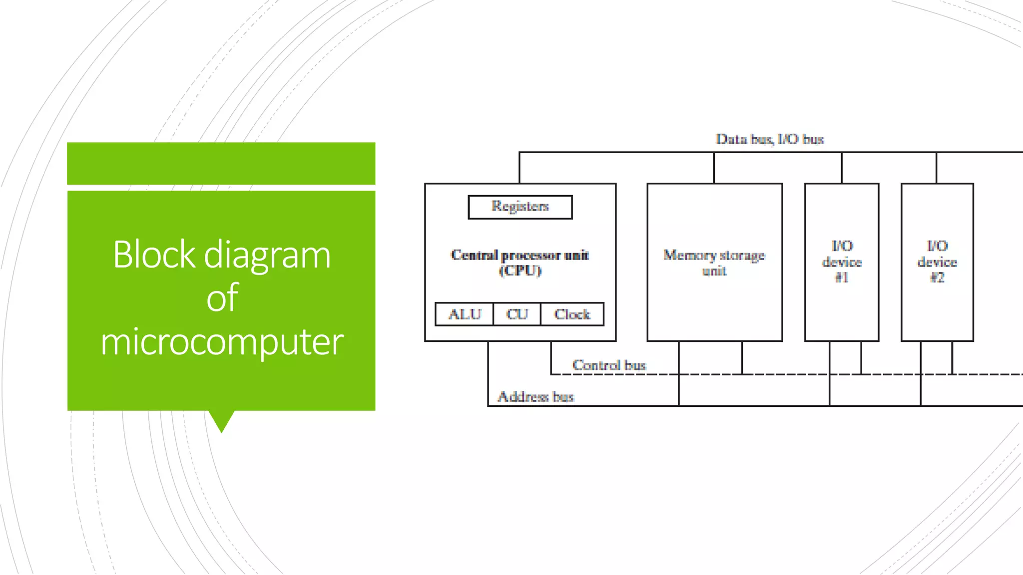
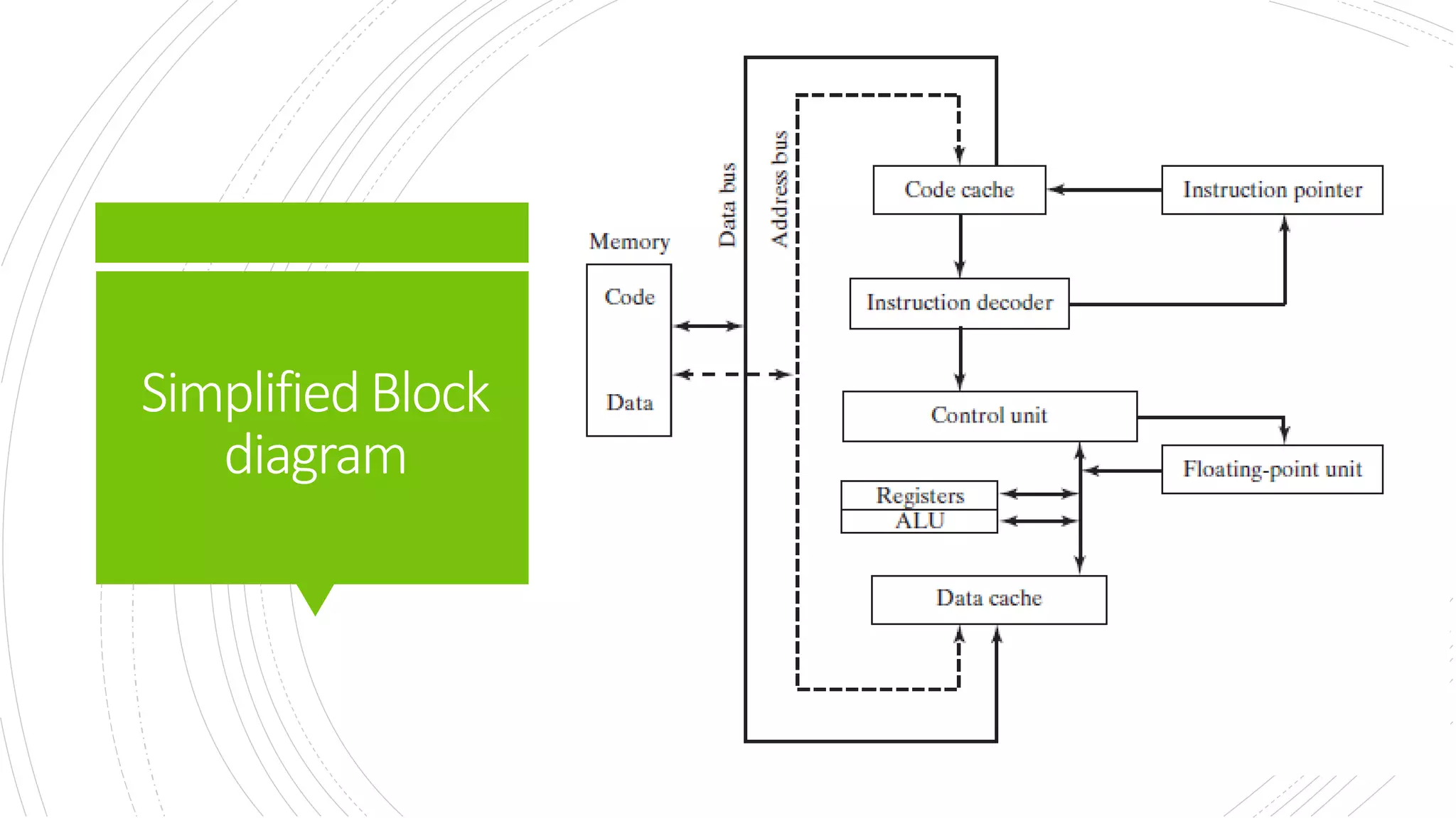
This document provides an overview of the basic design of a microcomputer. It describes the central processing unit (CPU) which contains registers, a clock, control unit, and arithmetic logic unit to perform calculations and logical operations. The CPU is connected via buses to memory storage where instructions and data are held, and to input/output devices. The clock synchronizes operations, with each clock cycle being the basic unit of time for executing machine instructions through a fetch-decode-execute cycle. Reading from memory is slower than accessing registers as it requires placing the address on the bus and waiting for the value to be returned.


![IntegerLiterals
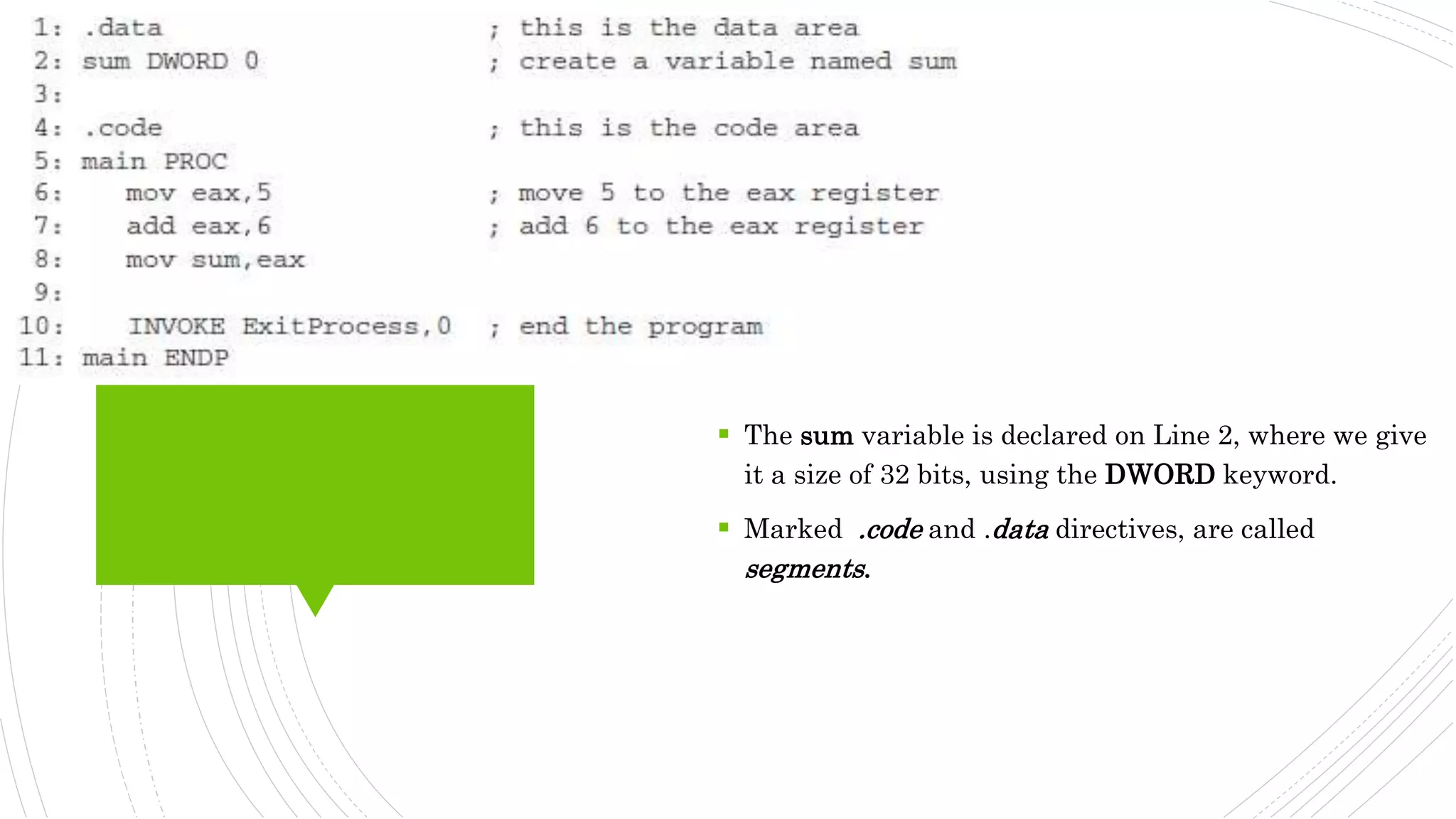
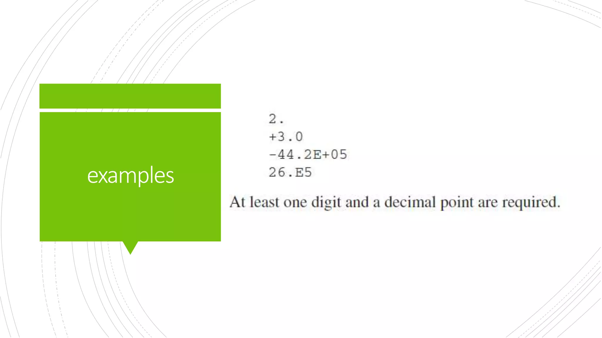
An integer literal (also known as an
integer constant) is made up of an
optional leading sign, one or more digits,
and an optional radix character that
indicates the number’s base
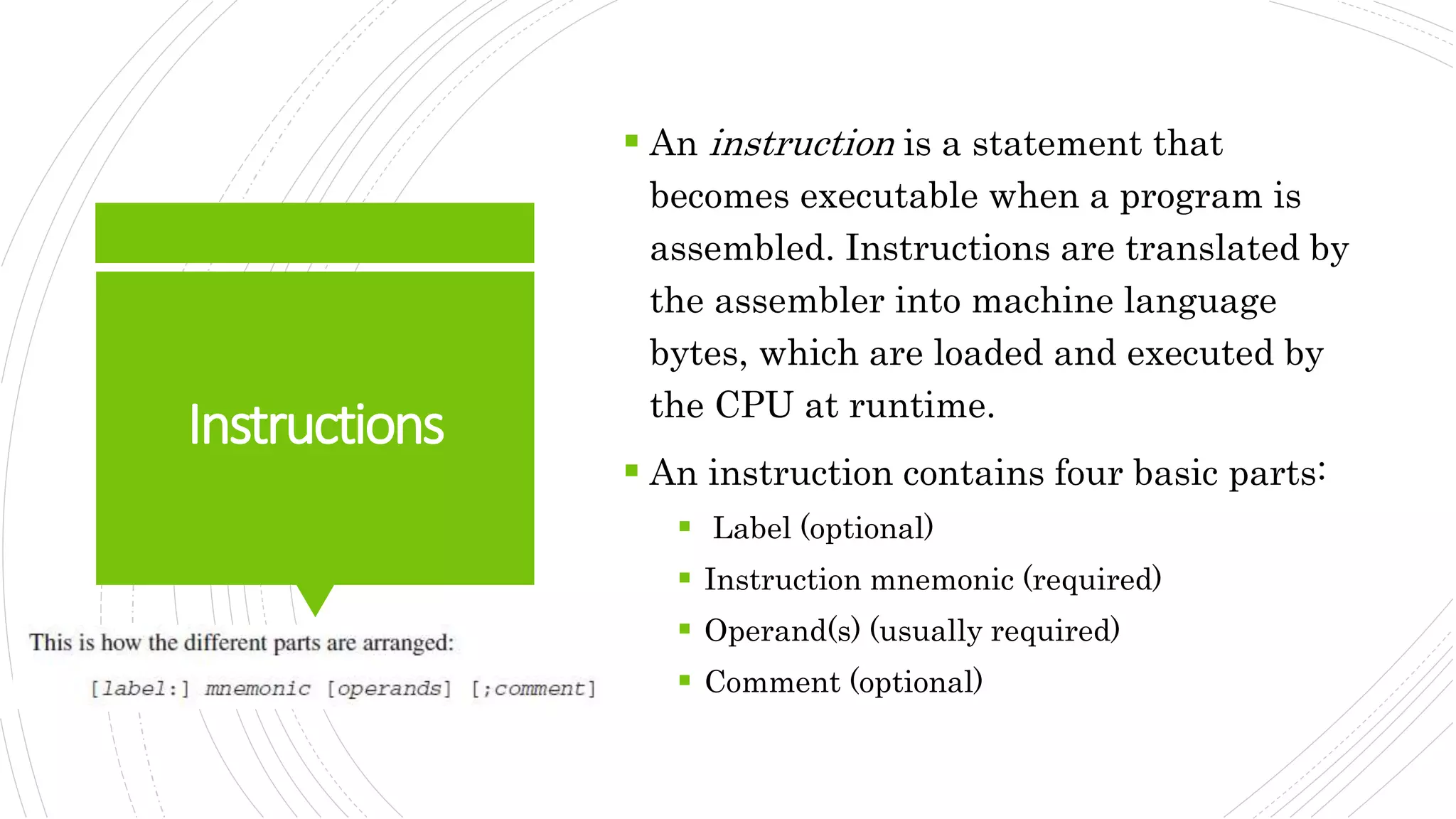
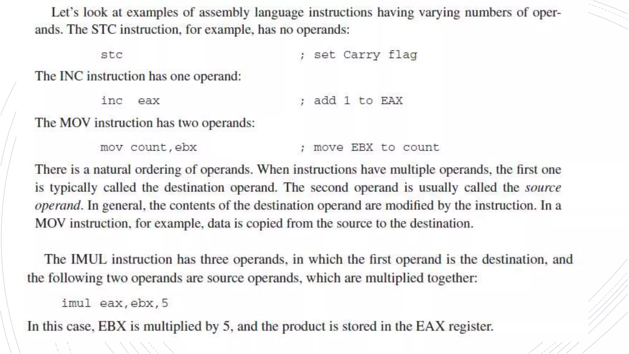
Elements within square brackets [..] are optional and elements within braces {..} require a choice of one
of the enclosed elements, separated by the | character. Elements in italics identify items that have
known definitions or descriptions.](https://image.slidesharecdn.com/introtoassemblylanguage-221120213345-1219b238/75/intro-to-assembly-language-pptx-20-2048.jpg)


![Chap03[1]](https://cdn.slidesharecdn.com/ss_thumbnails/chap031-140914002717-phpapp01-thumbnail.jpg?width=640&height=640&fit=bounds)


![Vibe Coding vs. Spec-Driven Development [Free Meetup]](https://cdn.slidesharecdn.com/ss_thumbnails/vibecodingvsspecdrivendevelopment-251209105622-43f455e7-thumbnail.jpg?width=640&height=640&fit=bounds)


