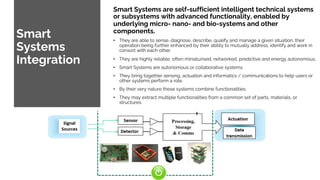
2. Smart structure
Smart structure incorporates sensors and actuators into the material of the structure in such a
way that enables the structure to sense its environment and then respond appropriately in a pre-
programmed manner.
Data Acquisition (tactile sensing): the aim of this component is to collect the required raw data
needed for an appropriate sensing and monitoring of the structure. LOAD 50 SENSOR ACTUATOR
Electric Field 5mV
Data Transmission (sensory nerves): the purpose of this part is to forward the raw data to the
local and/or central command and control units.
Command and Control Unit (brain): the role of this unit is to manage and control the whole
system by analyzing the data, reaching the appropriate conclusion, and determining the actions
required. LOAD 50 Electric Field 5mV CONTROL UNIT 5mV means LOAD:50 Recover LOAD:50
LOAD:50 APPLY 10mV
Data Instructions (motor nerves): the function of this part is to transmit the decisions and the
associated instructions back to the members of the structure.
Action Devices (muscles): the purpose of this part is to take action by triggering the controlling
devices/ units. CONTROL UNIT LOAD 50 Electric Field 10mV LOAD 50 CMPENSATING 50
3. Smart
Systems
Integration
Smart Systems are self-sufficient intelligent technical systems
or subsystems with advanced functionality, enabled by
underlying micro- nano- and bio-systems and other
components.
• They are able to sense, diagnose, describe, qualify and manage a given situation, their
operation being further enhanced by their ability to mutually address, identify and work in
consort with each other.
• They are highly reliable, often miniaturised, networked, predictive and energy autonomous.
• Smart Systems are autonomous or collaborative systems.
• They bring together sensing, actuation and informatics / communications to help users or
other systems perform a role.
• By their very nature these systems combine functionalities.
• They may extract multiple functionalities from a common set of parts, materials, or
structures.
4. Low carbon insulated concrete walls and floors
The System consists of two types of wall panels that combine to
provide a panel system that is capable of being used for all
elements of a structural building. Panels are made structural
through the application of high strength concrete sprayed to
the surfaces in the case of the single panel or poured into the
cavity for the double panel.
The first type is the single panel which consists of an EPS
rigid core with prefabricated, galvanized, high tensile steel
wire mesh reinforcement (600Mpa). Following erection on
site it is sprayed both sides in shotcrete (concrete) creating a
structural building.
The second type of panel is the double panel. The double
panel is made up of two basic panels, shaped as required and
joined together by double horizontal connectors tying the two
panels together throughout the section (acting as the rebar).
This creates a hollow core which is then filled with the
concrete of required strength to meet the project needs.
5. External Clad options:
• You can spray both sides in shotcrete
• You can render it
• You can brick face it
• You can timber clad it
• You can panel it
The exterior options are endless as you can mechanically
fix through the insulation into the concrete core for
permanent fixing.
This system also includes the required floor, stairs and roof
panels which are permanent shutters for in situ poured
concrete.
The system is perfect for all building types; residential,
schools, hospitals, garden offices, outbuildings, the list is
endless.
6. 1. Integrated flooring
systems in multistory
commercial buildings
• Most multi-story commercial buildings are very wasteful of the space above the finished ceiling and below the floor of
the level above. This is the “sandwich” volume for various building systems such as: structures, HVAC, electrical,
communications, plumbing, and fire protection.
• To make the design process simpler, the design team often allocates an independent volume to each of the systems, a
typical example of which is shown in Figure 2.
• Under the floor, the structural spanning system has been given its own volume, having a horizontal extent equal to
the footprint of the building and a vertical dimension great enough to accommodate the deepest spanning beam or
truss.
• Beneath that volume, the HVAC system has been given its own volume, having a horizontal extent equal to the
footprint of the building and a vertical dimension great enough to accommodate the largest duct in the system.
• Beneath that, electric lighting has been given its own volume, having a horizontal extent equal to the footprint of the
building and a vertical dimension great enough to allow electric lighting fixtures to be maneuvered and inserted
between the T-bars of the hung ceiling.
• The design process thereby becomes more like volume allocation, rather than system integration. In this process, vast
amounts of the ‘sandwich’ volume are filled only with air.
7. 2. An integrated roofing system
incorporating dynamically
adjustable, remote shading for
daylighting apertures
• Most multi-story commercial buildings are very wasteful of the space above the finished ceiling and below the floor of
the level above. This is the “sandwich” volume for various building systems such as: structures, HVAC, electrical,
communications, plumbing, and fire protection.
• To make the design process simpler, the design team often allocates an independent volume to each of the systems, a
typical example of which is shown in Figure 2.
• Under the floor, the structural spanning system has been given its own volume, having a horizontal extent equal to
the footprint of the building and a vertical dimension great enough to accommodate the deepest spanning beam or
truss.
• Beneath that volume, the HVAC system has been given its own volume, having a horizontal extent equal to the
footprint of the building and a vertical dimension great enough to accommodate the largest duct in the system.
• Beneath that, electric lighting has been given its own volume, having a horizontal extent equal to the footprint of the
building and a vertical dimension great enough to allow electric lighting fixtures to be maneuvered and inserted
between the T-bars of the hung ceiling.
• The design process thereby becomes more like volume allocation, rather than system integration. In this process, vast
amounts of the ‘sandwich’ volume are filled only with air.