SlideShare a Scribd company logo
1 of 92
Download to read offline
ATN PVS-14
o p e r a t o r ’s m a n u a l
Important Export Restrictions! Commodities, products,
technologies and services contained in this manual are
subject to one or more of the export control laws and
regulations of the U.S. Government and they fall under the
control jurisdiction of either the US Department of State
or the US BIS-Department of Commerce. It is unlawful
and strictly prohibited to export, or attempt to export or
otherwise transfer or sell any hardware or technical data or
furnish any service to any foreign person, whether abroad
or in the United States, for which a license or written
approval of the U.S. Government is required, without
first obtaining the required license or written approval
from the Department of the U.S. Government having
jurisdiction. Diversion contrary to U.S. law is prohibited.
OPERATOR’S MANUAL (PVS-14/6015) REVISION 2 - APRIL 2011
ATN 6015NIGHT VISION MULTI-PURPOSE SYSTEMS
The information in this manual furnished for information use only, is subject to
change without notice, is not to be construed as a commitment by ATN Corp.
ATN Corp. assumes no responsibility or liability for any errors or
inaccuracies that may appear in this book.
© 2011 ATN Corp. All right reserved.
Register your product warranty online at
www.atncorp.com/warranty
a
SAFETY SUMMARY
CAUTIONS
• The ATN PVS-14 and ATN 6015 are precision optical instruments
and must be handled carefully at all times to prevent damage.
• Do not scratch the external lens surfaces or touch them with your
fingers.
• Wiping demisting shield with lens paper while wet or with wet lens
paper can damage the coating.
• To protect the image intensifier, keep the lens cap on the objec-
tive lens when the monocular is not in use or when checked out in
daylight conditions.
• The IR illuminator is the light that is invisible to the unaided eye
for use during conditions of extreme darkness. However, the light
from the illuminator can be detected by others when using night
vision devices.
• If you use the rubber eyecaps for a long period of time, you may
suffer skin inflammation. If you develop any symptoms, consult a
doctor immediately.
WARNING
Do not carry batteries in pockets containing metal objects such as
coins, keys, etc. Metal objects can cause the batteries to short cir-
cuit and become very hot.
THIS PRODUCT CONTAINS NATURAL RUBBER LATEX WHICH MAY
CAUSE ALLERGIC REACTIONS.
CAUTION:
b
WARNING
Toxic Material
The image intensifier’s phosphor screen contains toxic
materials.
• If an image intensifier breaks, be extremely careful to avoid
inhaling the phosphor screen material. Do not allow the mate-
rial to come in contact with the mouth or open wounds on the
skin.
• If the phosphor screen material contacts your skin, wash it off
immediately with soap and water.
• If you inhale/swallow any phosphor screen material, drink a
lot of water, induce vomiting, and seek medical attention as
soon as possible.
WARNING
The monocular will not be turned off automatically when flipped
up. The monocular must be turned off by the power switch.
WARNING
The compass illuminator can be seen by others using night
vision devices.
WARNING
Do not use contaminated eyecup or eyeguard. They must be
replaced.
WARNING
When installing the headmount over the protective mask, be
careful not to break the protective mask seal around your face.
c
EQUIPMENT LIMITATIONS
To avoid physical and equipment damage when using the ATN
PVS-14 and ATN 6015, carefully read and understand the following
safety precautions.
• The equipment requires some night light (moonlight, starlight,
etc.) to operate. The level of performance depends upon the
level of light.
• Night light is reduced by passing cloud cover, while operating
under trees, in building shadows, etc.
• The equipment is less effective viewing into shadows and other
darkened areas.
• The equipment is less effective through rain, fog, sleet, snow
or smoke.
• The equipment will not “see” through dense smoke.
NOTES
• At operating temperatures below -20°C (-4°F), alkaline bat-
teries are not recommended, as operating life will be severely
reduced. Lithium-iron disulfide 1.5V AA batteries or equivalent
should be used below -20°C (-4°F).
• The purpose of the illuminator is to view at close distance up
to 3 meters when additional illumination is needed.
CAUTION
• The ATN PVS-14 and ATN 6015 are a precision optical instru-
ment and must be handled carefully at all times to prevent
damage.
• Be careful when leaving the helmet mount in the flipped
up position or removing the helmet mount from the helmet,
damage can result.
i
TABLE OF CONTENTS
	pg.
SAFETY SUMMARY	 a
CHAPTER 1. INTRODUCTION	 1-1
1.1.	 General Information	 1-2
1.1.1.	Scope	 1-2
1.1.2.	 Warranty Information	 1-2
1.1.3.	 Technical Information	 1-2
1.1.4.	 Nomenclature Cross-Reference List	 1-2
1.1.5.	 List of Abbreviations And Acronyms	 1-4
1.1.6.	Glossary	 1-5
1.2.	 Equipment Description	 1-7
1.2.1.	 Equipment Characteristics, Capabilities,
and Features	 1-8
1.2.2.	 Location and Description Of Major Components	 1-8
1.2.3.	 Equipment Data	 1-13
1.3.	 Principles of Operation	 1-15
1.3.1.	 Mechanical Functions	 1-15
1.3.2.	 Optical Functions	 1-16
1.3.3.	 Electronic Circuit Function	 1-16
CHAPTER 2. OPERATING INSTRUCTIONS	 2-1
2.1.	 Description and Use of Operator’s controls and
indicators	2-2
2.1.1.	 Operator Controls and Indicators	 2-2
2.2.	Preventive Maintenance Chec ks and
Service s (PMCS)	 2-4
2.2.1.	 Preventive Maintenance Checks and
Services Table	 2-4
2.2.2.	 Resolution Check Using the
TS-4348/UV Test Set	 2-14
2.2.3. Inspection Criteria for Proper Image Intensifier
Operation	2-16
2.3.	 General Information	 2-21
2.3.1.	Unpacking	 2-21
ii
2.3.2.	 Installation of Battery	 2-21
2.3.3.	 Installation of Eyecup Or Eyeguard	 2-23
2.3.4.	 Installation of Demist Shield	 2-23
2.3.5.	 Installation of Sacrificial Window	 2-24
2.3.6.	 Installation of LIF	 2-24
2.3.7.	 Installation and Adjustment of Headmount	 2-25
2.3.8.	 Installation of Headmount/Helmet
Mount Adapter	 2-27
2.3.9.	 Installation of Helmet Mount to Helmet	 2-27
2.3.10.Installation of Headmount with Protective Mask	 2-29
2.3.11.	Installation of Weapon Mount	 2-30
2.3.12.	Installation of Compass Caution	 2-31
2.3.13.	Installation of 3x Magnifier	 2-33
2.4.	Operating Procedures	 2-34
2.4.1.	 Hand-Held Operation	 2-34
2.4.2.	 Head Mounted Operation	 2-34
2.4.3.	 Helmet Mounted Operation	 2-36
2.4.4.	 Weapon Mounted Operation	 2-38
2.4.5.	 IR Source Operations	 2-39
2.4.6.	 Operation with Compass	 2-39
2.4.7.	 Operation with 3x Magnifier	 2-41
2.4.8.	 Operation with Gain Control	 2-41
2.4.9.	 Preparation for Storage	 2-42
2.5.	 Operation under Unusual Condition	 2-43
2.5.1.	 Operation in Dusty or Sandy Areas	 2-43
2.5.2.	 Operation in Rainy or Humid Conditions	 2-43
2.5.3.	 Operation in Salt Water Areas	 2-43
2.5.4.	 Operation in Nuclear, Biological and
Chemical (NBC) Environments	 2-44
2.5.5.	 Operation in Laser Threat Environments	 2-44
CHAPTER 3. MAINTENANCE INSTRUCTIONS	 3-1
3.1.	 Lubrication Instructions	 3-2
3.2.	Troubleshooting Procedures	 3-2
3.3. Operator ’s Maintenance Procedures	 3-6
3.3.1.	 Cleaning the MUNVM	3-6
iii
3.3.2.	Headmount Maintenance	 3-6
3.3.3.	Neck Cord Maintenance	 3-8
Appendix A. Components of End Item (COEI)
and Basic Issue Items (BII) Lists	 A-1
Appendix B. Additional Authorization List (AAL)	 B-1
Appendix C. Expendable and Durable Items List	 C-1
Subject Index	 IND-1
HOW TO USE THIS MANUAL
• Usage
You must familiarize yourself with the entire manual before operat-
ing the equipment. Read and follow all warning notices.
• Manual Overview
The table of contents includes the paragraph number, paragraph
title, and page number. An index provides additional references to
the subject contents.
1-1
CHAPTER 1
INTRODUCTION
1-2
1.1. GENERAL INFORMATION
1.1.1. SCOPE
This manual provides operation and maintenance instructions for
the Multi-Use Night Vision Monocular (MUNVM) ATN PVS-14 and
ATN 6015 hereinafter referred to as the MUNVM. The MUNVM is
a self-contained night vision device that enables improved night
vision using ambient light from the night sky (moon, stars, skyglow,
etc.).
Model Number and basic description
ATN NVM-14 and ATN 6015 – Multi-Use Night Vision Monocular
Supplier
American Technologies Network Corp.
1341 San Mateo Avenue
South San Francisco, CA 94080 USA
1.1.2. WARRANTY INFORMATION
This item shall conform to design, manufacturing, and performance
requirements and be free from defects in material and workman-
ship for a period of two (2) years from the date of acceptance. If item
is defective, notify ATN or point of purchase contact.
1.1.3. TECHNICAL INFORMATION
For technical information contact ATN Corp. directly at
(650) 989-5100, or info@atncorp.com or your point of purchase
contact.
1.1.4. NOMENCLATURE CROSS-REFERENCE LIST
Table 1.1. provides a cross reference of common names and official
terms. Except in the Appendices, the common names will be used.
The official names are used in the Appendices because they reflect
the provisioning nomenclature.
1-3
TABLE 1.1. NOMENCLATURE CROSS-REFERENCE LIST
COMMON NAME OFFICIAL NOMENCLATURE
Battery Battery Nonrechargeable
Battery Cap Cover Battery Retainer
Carrying Case Case, Infrared Equipment
Carrying Case Strap Strapping
Compass Compass Assembly
Demist Shield Lens, Infrared Receiver
Eyeguard Eyeguard, Optical
Eyepiece Lens Cap Cap, Protective, Dust
Headmount Headset Assembly
Headmount/Helmet Mount Adapter Adapter, Headset
Helmet Mount Mount, Viewer
LIF Filter, Infrared Light
Medium Browpad Browpad Assy, Medium
Monocular Monocular Assy
Neck Cord Cord, Fibrous
Objective Lens Cap Cap, Protective, Dust
Sacrificial Window Window, Sacrificial
Shipping and Storage Case Case, Shipping/Storage
Tethering Cord Clip, Retaining
Thick Browpad Browpad Assy, Thick
Thin Browpad Browpad Assy, Thin
3X Magnifier Magnifier Lens Assembly
Weapon Mount Bracket, Mounting
1-4
1.1.5. LIST OF ABBREVIATIONS AND ACRONYMS
AAL	 Additional Authorization List
BII		 Basic Issue Items
CAGEC	 Commercial and Government Entity Code
cm		 Centimeters
COEI	 Components of End Item
CPC	 Corrosion Prevention and Control-
CTA	 Common Table of Allowances-
DA		 Department of the Army
EIC		 End Item Code
EIR		 Equipment Improvement Recommendation
FM		 Field Manual
Hrs		 Hours
IR		 Infrared
JTA		 Joint Table of Allowances
lbs		 Pounds
LED	 Light Emitting Diode
LIF		 Light Interference Filter
MUNVM	 Multi-Use Night Vision Monocular
NVMPS	 Night Vision Multi-Purpose System
MTOE	 Modified Table of Organization and Equipment-
N/A	 Not Applicable
NBC	 Nuclear, Biological, and Chemical
NSN	 National Stock Number
Pam	Pamphlet
PASGT	 Personal Armor System Ground Troops
PMCS	 Preventive Maintenance Checks and Services
Qty		 Quantity
Recm	Recommended
Rqr		 Required
1-5
SF		 Standard Form
TDA	 Table of Distribution and Allowances-
TM		 Technical Manual
TOE	 Table of Organization and Equipment-
U/M	 Unit of Measure
Vdc		 Volts, direct current
1.1.6. GLOSSARY
BLACK SPOTS. These are cosmetic blemishes in the image inten-
sifier of the MUNVM or dirt or debris between the lenses.
BRIGHT SPOTS. These defects can appear in the image area of
the MUNVM. This condition is caused by a flaw in the film on the
microchannel plate. A bright spot is a small, nonuniform, bright area
that may flicker or appear constant. Bright spots usually go away
when the light is blocked out and are cosmetic blemishes that are
signal induced.
BROWPADS. Three hook-and-pile browpads are provided to adjust
the headmount to fit different head sizes. The thin browpad (large
head) comes attached to the headmount and the thick (small head)
or medium browpads are stored in the carrying case.
CAUTION. Condition, practices, or procedures that must be ob-
served to avoid damage to equipment, destruction of equipment, or
a long-term health hazard.
CHICKEN WIRE. An irregular pattern of dark thin lines in the field-
of-view either throughout the image area or in parts of the image
area. Under the worst case condition, these lines will form hexago-
nal or square-wave shaped lines.
DARK (OR DARK AREA). A place in which there is very little light.
It does not mean total darkness. Generally, this means conditions
similar to a quarter-moon or starlit night.
DARK-ADAPTED. Having ones eye adjusted to the monocular’s
output under low light conditions.
DIOPTER. A unit of measure used to define eye correction. Adjust-
ments to the diopter adjustment will provide a clearer image in each
eye.
1-6
EDGE GLOW. This is a defect in the image area of the monocular.
Edge glow is a bright area (sometimes sparkling) in the outer por-
tion of the viewing area.
EMISSION POINT. A steady or fluctuating pinpoint of bright light in
the image area and does not go away when all light is blocked from
the objective lens of the monocular. The position of an emission
point within the image area of the monocular does not move. An
emission point should not be confused with a point light source in
the distance.
FIXED-PATTERN NOISE. This is a cosmetic blemish in the im-
age area characterized by a faint hexagonal (honeycomb) pattern
throughout the viewing area that most often occurs at high light
levels or when viewing very bright lights. Fixed-pattern noise is in-
herent in the structure of the fiber optics and can be seen in every
image intensifier if the light level is high enough.
FLASHING. This is a defect in the image area of the monocular.
The image appears to flicker or flash.
FLICKERING. See “flashing.”
GAIN. This is the number of times a night vision device amplifies
light input.
IMAGE INTENSIFIER. An electro-optical device that detects and
amplifies ambient light to produce a visual image.
INFINITY FOCUS. Adjustment of the objective lens so that a distant
object, such as a star or the point light on a distant tower, forms the
sharpest image.
INTERMITTENT OPERATION. This is a defect in the image area of
the monocular. See “flashing”.
IR SOURCE. This is an IR Light Emitting Diode (LED). When turned
on, the IR source provides additional illumination to enhance exist-
ing light conditions used only for performing nearby tasks.
LIGHT INTERFERENCE FILTER (LIF). This is a light protection fil-
ter for the monocular. Use of this filter will result in a slight reduction
in system gain.
MICROCHANNEL PLATE. A current-multiplying optical disk that
intensifies the electron image produced by the photocathode.
1-7
NOTE. Essential information of special importance, interest, or aid
in job performance.
PHOTOCATHODE. The input optic of an image intensifier that ab-
sorbs light energy and in turn releases electrical energy in the form
of an electron image.
SCINTILLATION. A faint, random, sparkling effect throughout the
image area. Scintillation is a normal characteristic of the image in-
tensifier and should not be confused with emission points. Scintil-
lation is more pronounced under low light conditions. Also called
“video noise”.
SHADING. The viewed image should be a full circle. If shading is
present, you will not see a fully circular image. Shading is indicative
of a dying photocathode and is caused by a defective vacuum seal
of the image intensifier. Shading is very dark and you cannot see
an image through it.
WARNING. Conditions, practices, or procedures that must be ob-
served to avoid personal injury or loss of life.
1-8
1.2 EQUIPMENT DESCRIPTION
1.2.1. EQUIPMENT CHARACTERISTICS,
CAPABILITIES, AND FEATURES
The MUNVM is a hand-held, headmounted, helmet mounted, or
weapon mounted night vision system that enables walking, weapon
firing, short-range surveillance, map reading, vehicle maintenance,
and administering first aid in both moonlight and starlight. Each unit
allows for vertical adjustment (by using head strap), fore-and-aft
adjustment, objective lens focus and eyepiece focus. The monocu-
lar is also equipped with an IR source and a low battery indicator.
The PVS-14 model equipped with a manual gain control.
1.2.2. LOCATION AND DESCRIPTION OF MAJOR
COMPONENTS
The NVMPS includes the items shown in Figures 1.1., 1.2., 1.3. The
major components are the headmount, helmet mount, monocular,
carrying case, and the shipping and storage case.
a. Monocular
The monocular (see Figure 1.4.) consists of various components
such as an objective lens, an image intensifier (not shown), an eye-
piece lens and a battery cap.
The monocular also uses the accessories listed below:
	 Demist Shield – The demist shield (Figure 1.1.) is used to
prevent the eyepiece lenses from becoming fogged.
	 Light Interference Filter (LIF) – The LIF (Figure 1.1.) is to be
used at all times. For replacing the filter the container is also
the wrench. The container/wrench is used to remove and
replace the LIF from the objective lens.
	 Sacrificial Window – A replaceable sacrificial window
(Figure 1.1.) is supplied to protect the objective lens during
operation in adverse conditions.
	 Compass – The compass (Figure 1.2.) enables the operator to
see azimuth readings in the monocular.
1-9
FIGURE 1.1. COMPONENTS OF NVMPS
HEAD/HELMET
MOUNT ADAPTER
TETHERING
CORD
HEADMOUNT
THIN
BROWPAD
HELMET MOUNT
WEAPON MOUNT
BATTERY
CARTRIDGE
CARRYING
CASE
OPERATOR’S
MANUAL
MEDIUM AND
THICK BROW-
PADS
LENS
PAPER
CARRYING
CASE STRAP
SACRIFICIAL
WINDOW
DEMIST
SHIELD
EYEGUARD
BATTERYNECK CORD
OBJECTIVE
LENS CAP
MONOCULAR
LIF W/
CONTAINER
WRENCH
1-10
FIGURE 1.2. 3X MAGNIFIER AND COMPASS FOR PVS-14/6015
COMPASS
3X MAGNIFIER
(ADDITIONAL ITEM)
1-11
FIGURE 1.3. SHIPPING AND STORAGE CASES FOR PVS-14/6015
(SEE FIGURE 1.1. FOR DETAILS)
SHIPPING
AND
STORAGE
CASE
1-12
FIGURE 1.4. MULTI-USE NIGHT VISION MONOCULAR
OBJECTIVE
LENS
EYEPIECE
LENS
POWER
SWITCH
GAIN
CONTROL
BATTERY
CAP
	 Tethering Cord – The tethering cord (Figure 1.1.) enables the
user to attach the compass or 3X magnifier to a button hole or
belt loop to guard against dropping orlosing these items.
	 3X Magnifier – (Additional Authorized Item) The 3Xmagnifier
(Figure 1.2.) is a lens assembly which can be added to the
monocular to extend the operator’s observation ranges.
b. Headmount
The headmount (Figure 1.1.) secures the monocular to the opera-
tor’s head for night viewing and provides freehand support for use
with a weapon, protective mask or other purposes. It is adjustable
and cushioned. The thin browpad used for large heads, comes at-
tached to the headmount; the thick and medium browpads, used for
smaller heads are stored in the carrying case.
c. Helmet Mount
This item (Figure 1.1.), secures the monocular to the Personal Ar-
mor System Ground Troops (PASGT) helmet allowing freehand
support for use with a weapon, protective mask and/or other pur-
poses. The new helmet mount is made of a ruggedized metal. The
old one is made of plastic.
1-13
d. Headmount/Helmet Mount Adapter
This item (Figure 1.1.) is attached to the monocular to allow its use
with the headmount or helmet mount. It allows mounting in front of
the left or right eye.
e. Weapon Mount
The weapon mount (Figure 1.1.) adapts the monocular to the re-
ceiver rail as configured for the modular weapon system kit.
f. Carrying Case
The carrying case (Figure 1.3.) is provided for transportation and
protection of the monocular, headmount, battery and accesso-
ries. Two slide keepers are provided for belt attachment and three
D-rings for shoulder and leg strap attachment. A carrying case
strap is also provided which can be attached to the two D-rings on
the back of the carrying case.
g. Shipping and Storage Case
The NVMPS is supplied in a shipping and storage case
(Figure 1.3.).
1.2.3. EQUIPMENT DATA
The following tables provide information pertaining to the opera-
tional, electrical, mechanical, optical, and environmental charac-
teristics for the monocular.
TABLE 1.2. OPERATOR ADJUSTMENT LIMITS
ITEM LIMITS
Diopter Focus +2 to –6 diopters
Objective Focus 25 cm to infinity
TABLE 1.3. ELECTRICAL DATA
ITEM DATA
Power Source Battery (1.5 Vdc max ea.)
Battery Requirements
1 AA Alkaline or
1 AA 1.5 Vdc Lithium L91
1-14
TABLE 1.4. MECHANICAL DATA
ITEM CHARACTERISTICS
Shipping and Storage Case
Size: Approx.14” X 9.5” X 8”
Weight: 2.4 lbs.
Carrying Case Size: Approx. 14” X 8”
Monocular (see Note) Weight: 14 ounce
NOTE
Weight of the monocular does not include accessories.
TABLE 1.5. OPTICAL DATA
ITEM DATA
Magnification 1.0X (3X with 3X magnifier)
Field-of-View 40 (13 with 3X magnifier)
Diopter Focus +2 to - 6 diopters
Objective Focus 25 cm (9.8”) to infinity
TABLE 1.6. ENVIRONMENTAL DATA
ITEM DATA
Monocular Operating Temperature -51°C to +49°C
Monocular Storage Temperature -51°C to +85°C
Illumination Required Overcast starlight to moonlight
1-15
1.3. PRINCIPLES OF OPERATION
1.3.1. MECHANICAL FUNCTIONS
The mechanical functions of the NVMPS allow for differences in the
physical features of individual operators and provide for operating
the system. These functions include the power switch, eye relief
adjustment, diopter adjustment, gain control, and objective focus.
The mechanical controls are identified in Figure 1.5.
FIGURE 1.5. MECHANICAL FUNCTIONS FOR THE NVMPS
NOTE
The gain control is not present in 6015 or PVS-14NG model.
OBJECTIVE
FOCUS
DIOPTER
ADJUSTMENT
POWER
SWITCH
GAIN
CONTROL
EYE RELIEF
ADJUSTMENT
HIGH LIGHT
CUT-OFF
WINDOW
IR LENS
LATCH
1-16
1.3.2 OPTICAL FUNCTIONS
The optical functions include an objective lens, image intensifier
and eyepiece lens (Figure 1.6). The objective lens collects light re-
flected from the night scene by the moon, stars, or night sky, inverts
the image and focuses that image on the image intensifier. The im-
age intensifier converts the captured light into a visible image and
reinverts the image which can then be viewed through the eyepiece
lens.
FIGURE 1.6. OPTICAL FUNCTION DIAGRAM
1.3.3. ELECTRONIC CIRCUIT FUNCTION
The electronic circuit regulates the direct current voltage from the
battery to the image intensifier and IR source as required. It also
monitors the output voltage of the battery and turns on a low-bat-
tery indicator when the available battery voltage is 1.9 – 2.1Vdc.
a. Power Source
The electronic circuit is powered by one battery.
b. High Light Cut-Off
The monocular will automatically cut off after 70 ±30 seconds of
operation in daylight or bright room light. Individual bright lights
(headlights, flashlights, or other concentrated light sources) will not
actuate the high light detector located on the front of the monocular.
To turn the monocular back ON, turn the power switch to RESET/
OFF position and then to ON again.
PHOTOCATHODE
MICROCHANNEL
PLATE
FIBER-OPTIC INVERTER
PHOSPHOR
SCREEN
OBJECTIVE
LENS
IMAGE
INTENSIFIER
POWER
SUPPLY
EYEPIECE
LENS
EYE
2-1
CHAPTER 2
OPERATING INSTRUCTIONS
2-2
2.1. DESCRIPTION AND USE OF
OPERATOR’S CONTROLS AND
INDICATORS
NOTE
The MUNVM is a precision electro-optical instrument, so
handle it carefully. If the equipment fails to operate, refer to the
Troubleshooting Procedures in Chapter 3.
2.1.1. OPERATOR CONTROLS AND INDICATORS
The MUNVM is designed to adjust for different users and cor-
rects for most differences in eyesight. The controls and indicators
for the MUNVM are shown in Figure 2.1., which are described in
Table 2.1.
Figure 2.1. Monocular Controls and Indicators
NOTE
The gain control is not present in 6015 or PVS-14NG model.
NOTE
Low battery indicator and IR source “ON” indicator are vis-
ible in eyepiece lens.
BATTERY POLARITY
INDICATORS (HIDDEN)
HIGH LIGHT
CUT-OFF
WINDOW
OBJECTIVE
FOCUS
IR LENS
LATCH
DIOPTER ADJUST-
MENT
EYE RELIEF
ADJUSTMENT
POWER
SWITCH
GAIN
CONTROL
2-3
TABLE 2.1. MONOCULAR CONTROLS AND INDICATORS
CONTROLS AND
INDICATORS
FUNCTIONS
Power Switch Controls monocular and IR source, ON or OFF.
RESET/
OFF
Same as system OFF. Also resets monocular
after high light cut-off.
ON Monocular activated.
IR/
PULL
Turn the knob clockwise to momentarily ac-
tivate the IR source. Pull and turn the knob
clockwise from the ON position to continu-
ously activate theIR source.
CAUTION
Do not use excessive force to place the power switch into the momentary
IR position.
Low Battery
Indicator
When blinking it indicates a low battery condition with
less than 30 minutes of battery life remaining. It is
visible through the eyepiece just outside the intensified
field-of-view.
IR Source On
Indicator
When blinking it indicates a low battery condition with
less than 30minutes of battery life remaining. It is
visible through the eyepiece just outside the intensified
field-of-view.
Gain Control
(PVS-14 only)
Adjusts the system gain from a minimum value of
approximately 25 to a maximum value greater than
3,000.
Objective
Focus
Focuses objective lens. Adjusts for sharpest image of
viewed object.
Diopter
Adjustment
Focuses eyepiece lens for use without the need
for glasses. Adjust for sharpest image of intensifier
screen.
Eye Relief
Adjustment
Adjusts the distance between your eye and the
monocular.
Latch Latch used for separation of monocular from head-
mount/helmet mount adapter.
Battery Polar-
ity Indicators
This feature, molded into the battery housing, shows
the proper orientation of the battery. Some versions
have a bubble molded into the top of the battery house,
to show the + for proper orientation.
2-4
2.2. PREVENTIVE MAINTENANCE
CHECKS AND SERVICES (PMCS)
2.2.1. PREVENTIVE MAINTENANCE CHECKS AND
SERVICES TABLE
a. General
To ensure the readiness of the MUNVM, perform the preventive
maintenance procedures in accordance with Table 2.2., prior to
each mission. Preventive maintenance procedures include inspec-
tion, cleaning, and performance of the checkout procedures.
b. Warnings and Cautions
Always observe the WARNINGS and CAUTIONS appearing in the
table. Warnings and cautions appear before applicable procedures.
You must observe the warnings and cautions to prevent serious in-
jury to yourself and others, or to prevent your equipment from being
damaged.
c. Explanation of Table Entries
(1) Item Number Column. Numbers in this column are for refer-
ence. When completing Equipment Inspection and Maintenance
Worksheet, include the item number for the check/service indicat-
ing a fault. Item numbers also appear in the order that you must do
checks and services for the intervals listed.
(2) Interval Column. This column tells you when you must do the
procedure in the procedure column. BEFORE procedures must be
done before you operate or use the equipment for its intended mis-
sion. DURING procedures must be done during the time you are
operating or using the equipment for its intended mission. AFTER
procedures must be done immediately after you have operated or
used the equipment.
(3) Location, Check/Service Column. This column provides the
location and the item to be checked or serviced. The item location
is underlined.
(4) Procedure Column. This column gives the procedure you must
do to check or service the item listed in the Check/Service column
2-5
to know if the equipment is ready or available for its intended mis-
sion or operation. You must do the procedure at the time stated in
the interval column.
(5) Not Fully Mission Capable If: Column. Information in this
column tells you what faults will keep your equipment from being
capable of performing its primary mission. If you make check and
service procedures that show faults listed in this column, do not
operate the equipment. Follow standard operating procedures for
maintaining the equipment or reporting equipment failure.
NOTE
Damaged accessory items (sacrificial window, demist shield,
compass) do not cause the entire end item to be “not fully mis-
sion capable”. However, the damaged item should be replaced
as soon as practical to restore full capability of the system.
d. Other Table Entries
Be sure to observe all special information and notes that appear in
your table.
2-6
TABLE2.2.PREVENTIVEMAINTENANCECHECKSANDSERVICESFORTHEMUNVM.
ITEM
NO.
INTER-
VAL
LOCATION
PROCEDURE
NOTFULLY
MISSION
CAPABLEIF:
CHECK/
SERVICE
1BeforeOpencarryingcaseandchecktheinven-
toryitems
2Before/
After
MONOCULAR
Optical
Surfaces
Inspectalllenses(objective,eyepiece,IR
lensandhighlightcut-offwindow)fordirt,
fingerprintresidue,chips,orcracks.Ifnec-
essary,cleananddrylenseswithwater
andlenstissue.
Scratchesorheavy
scratchesthathinder
visionwithmonocu-
larturnedON,orif
cracksarepresent.
3Before/
After
BatteryCap
Housing
Inspectexternalsurfacesforcracksor
damage.Scratches,cracks,andgouges
areOKifoperationisnotaffected.
Inspectbatterycompartment.Checkto
makesurebatterycapispresent.Re-
movebatterycapandinspectformoisture,
cracks,corrodedordefectivespringcon-
tacts,ando-ringpresentincap.
Cracksordamagein
thebatteryhousing.
Capismissing,con-
tactsdamaged,or
corroded,o-ringis
missing.
2-7
ITEM
NO.
INTER-
VAL
LOCATION
PROCEDURE
NOTFULLY
MISSION
CAPABLEIF:
CHECK/
SERVICE
3.
Cont.
Before/
After
BatteryCap/
Housing
Cont.
Removebatteryandturnthepowerswitch
fromRESET/OFFtoONtoIR/PULL.Each
positionshouldhaveadefinitestopping
point.Inspectforbrokenormissingknob.
Installbatteryperparagraph2.6.andcheck
IRsource(andmomentaryIRsource,ifso
equipped)functionsbyfollowingtheoper-
atinginstructionsinparagraph2.22.
Checkthehighlightcut-offwithdaylightor
brightroomlight(notfluorescentlight)by
placingthelenscapontheobjectivelens.
TurnmonocularONandobservethatthe
systemcutsOFFwithin70±30seconds.
Powerswitchhas
nodefinitestopping
pointsorknobisbro-
kenormissing.
IRsourcedoesnot
work.
Ifdamaged,referto
higherlevelofmain-
tenance.
2-8
ITEM
NO.
INTER-
VAL
LOCATION
PROCEDURE
NOTFULLY
MISSION
CAPABLEIF:
CHECK/
SERVICE
3.
Cont.
Before/
After
BatteryCap/
Housing
Cont.
TurnmonocularOFFandthenONtoreen-
ergizemonocular.
NOTE
Ifthemonocularfailsthishighlightcut-off
test,itdoesnotcausetheenditemtobe
nonmissioncapable.However,itshouldbe
senttohigherlevelofmaintenanceassoon
aspossible.
Checkgaincontrolforfreemovementand
operationperparagraph2.25.
Knobisnotfreemoving
ordoesnotvarygain.
4Before/
After
MonocularInspectforcracksordamage.Scratches,
cracks,chipsandgougesareOKifopera-
tionisnotaffected.
Cracksordamagein
themonocular.
5Before/
After
EyepieceLensRotatediopteradjustmenttomakesure
theeyepiecelensmovesfreelyandisnot
loose.Rangeisapproximately½turn.
Binding,notmoving
freelyortooloose.
6Before/
After
EyecupInspectfordirt,dust,crackedortorneye-
cup.Inspectforbent,broken,orimproper-
lyfittingeyepiecelens.Ifnecessary,clean
withwater.
Chipsandcracksare
permittedontheeye-
cupretainingringsas
longastheydonot
interferewithinstal-
lationofeyecup.
2-9
ITEM
NO.
INTER-
VAL
LOCATION
PROCEDURE
NOTFULLY
MISSION
CAPABLEIF:
CHECK/
SERVICE
7Before/
After
EyeguardInspectfordirt,dust,crackedortorneye-
guard.Inspectforbent,broken,orimprop-
erlyfittingeyeguard.Ifnecessary,clean
withwater.
Chipsandcracksare
permittedontheeye-
guardretainingrings
aslongastheydonot
interferewithinstalla-
tionofeyeguard.
8Before/
After
ObjectiveLensRotatefocusringtoensurefreemovement
(rangeisapproximately1/3turn).Check
objectivelensforchips,cracksanddents.
Checktheinfinityfocuslockingringfor
tightness.Checkforcracks.
Focusringisbinding
ornotabletomove.
Chips,cracks,or
dentspreventfull
field-of-view,instal-
lationofLIForthe
abilitytofocus.
Crackedorloose.
9Before/
After
NeckCordand
ObjectiveLens
Cap
Inspectforcracked,torn,ormissingob-
jectivelenscap.Inspectneckcordforcut,
damage,orlooseends.
Re-tieendsifnecessary.
Damaged.
2-10
ITEM
NO.
INTER-
VAL
LOCATION
PROCEDURE
NOTFULLY
MISSION
CAPABLEIF:
CHECK/
SERVICE
10Before/
After
ViewedImageNOTE
OperatormayusetheTS-4348/UVto
checkresolution(paragraph2.2.2).
Refertoparagraph2.2.3.toinspectforop-
erationaldefects.
Flickering,flashing,
edgeglow,orshad-
ingisobserved.
11
Before/
After
HEADMOUNT
Straps/Pads
NOTE
Ifanyofthefollowingitemsaredamaged
itdoesnotcausetheentireenditemtobe
“notfullymissioncapable”.However,the
damageditemshouldbereplacedassoon
aspracticaltorestorefullcapabilityofthe
system.
Inspectforcuts,tears,fraying,holes,
cracks,ordefectivefasteners.
Damagecauses
strapsorpadstobe
unserviceable.
12Before/
After
SocketInspectfordirt,dust,orcorrosion.
Insertmonocularlatchintosockettoverify
secureattachmentofmonoculartohead-
mount.Ifnecessary,cleansocketwith
water.
Damaged,latch
won’tlockoristoo
loose.
2-11
ITEM
NO.
INTER-
VAL
LOCATION
PROCEDURE
NOTFULLY
MISSION
CAPABLEIF:
CHECK/
SERVICE
13Before/
After
EyeRelief
Adjustment
Presstheeyereliefadjustmentandcheck
forfreemotion.Inspectfordamage.
Binding,damagedor
non-operationalslide
mechanism.
14Before/
After
HELMETMOUNT
StrapsInspectforcuts,tears,fraying,holes,
cracks,ordefectivefasteners.
Damagecauses
strapstobeunser-
viceable.
15Before/
After
SocketInspectfordirt,dust,orcorrosion.
Insertmonocularlatchintosockettoverify
secureattachmentofmonoculartohelmet
mount.Ifnecessary,cleansocketwithwa-
ter.
Damaged,latch
won’tlockoristoo
loose.
16Before/
After
Fore-and-AftAd-
justment
Pressthe2sidebuttonsonplasticmount
ordepresssideleveronmetalmountand
checkforfreemotion.
Inspectfordamage.
Binding,damagedor
non-operationalslide
mechanism.
17Before/
After
MOUNTING
ADAPTERS
Headmount/
HelmetMount
Adapter
Inspectfordirt,dustorcorrosion.
Insertintoheadmountorhelmetmount
sockettoverifysecureattachment.
Damaged,willnot
latchsecurely.
2-12
ITEM
NO.
INTER-
VAL
LOCATION
PROCEDURE
NOTFULLY
MISSION
CAPABLEIF:
CHECK/
SERVICE
18Before/
After
WeaponMountInspectfordust,dirtorcorrosion.Damaged,willnot
mounttomonocular
orwillnotmountto
rail.
19Before/
After
ACCESSORIES
CAUTION
Thecoatingonthedemistshieldcanbe
damagedifcleanedwhilewetorifcleaned
withwetlenspaper.Cleanonlywhenthe
demistshieldisdryandonlywithdry
paper.
Inspectfordirt,dust,scratchesordamage.
Ifnecessary,cleanwhenshieldisdryand
withdrylenstissueonly.
Damageorscratch-
eshindervisionwith
monocularon.
20Before/
After
LIFInspectfordirt,dust,scratchesordamage.
Ifnecessary,cleanperparagraph3.2.
Damageorscratch-
eshindervisionwith
monocularon.
21Before/
After
SacrificialWin-
dow
Inspectfordirt,dust,scratchesordamage.
Ifnecessary,cleanperparagraph3.2.
Damageorscratch-
eshindervisionwith
monocularon.
2-13
ITEM
NO.
INTER-
VAL
LOCATION
PROCEDURE
NOTFULLY
MISSION
CAPABLEIF:
CHECK/
SERVICE
22Before/
After
CompassInspectfordirt,dust,scratches,ordam-
age.Ifnecessary,cleanwithwateranddry
withlenstissue.
Installcompassandturnonmonocular.
Whentheilluminationbuttonisdepressed,
compassshouldbevisible.
Damagedorcom-
passisnotvisible.
23Before/
After
3XMagnifier(Ad-
ditionalAutho-
rizedItem)
Inspectopticalsurfacefordirt,dust,
scratchesorcracks.
Damageorscratches
hindervision.
24Before/
After
CARRYINGCASE
CaseRemoveallitemsandshakeoutloose
dirtorforeignmaterial.Inspectfortears,
cuts,excesswear,ordamagetomounting
clips.
25Before/
After
ShoulderStrapInspectforcuts,tears,orexcesswearor
damagedclips.
2-14
2.2.2. RESOLUTION CHECK USING
THE TS-4348/UV TEST SET
NOTE
The TS-4348/UV Test Set can be used by the operator to check
the resolution of a monocular at any time.
NOTE
The TS-4348/UV Test Set can be used by Direct Support/Inter-
mediate Level to perform the resolution testing 180 Day Serv-
ice. If a system fails it must be tested on the TS-3895A/UV Test
Set.
NOTE
Verify the resolution of the monocular using the TS-4348/UV
Test Set at every opportunity. The resolution cannot be accu-
rately measured without the test set.
The following procedures are designed to check the performance
of the image intensifier.
a. Setup
Before using the TS-4348/UV Test Set to set up and familia-rize
yourself with its operation and the warnings and cautions associ-
ated with that test equipment.
NOTE
• The resolution test must be performed in a darkened area.
Your eyes must be dark-adapted to perform this test. Review
the following test procedure before entering the dark area.
• Expect cosmetic blemishes, such as chicken wire, black
spots, and fixed-pattern noise, to stand out while viewing
through the TS-4348/UV Test Set when it is on the high light
level.This is acceptable.
• The rejection of any MUNVM for cosmetic defects must be
based on an outdoor evaluation and not the TS-4348/UV Test
Set.
b. Low Light and High Light Resolution Test Procedure
Test the monocular for low light and high light resolution perfor-
mance according to the following steps.
(1) Place the HIGH/LOW switch on the test set to the LOW position.
2-15
(2) Install the LIF per paragraph 2.3.6.
(3) Turn off the room light and let your eyes adjust to the dark.
(4) Turn on the test set by setting the “II/OFF/III” switch to the “III”
position.
(5) Turn on the monocular and insert it into the test port on the test
set.
(6) Look through the monocular and view the projected pattern (see
Figure 2.2.). If necessary, focus the eyepiece lens and then the
objective lens to obtain the sharpest image.
(7) The MUNVM monocular must be able to resolve Group 2, Ele-
ment 2, under low light conditions to pass the test. If the MUNVM
does not pass the test, return it to maintenance for repair. The op-
erator must document resolution failures on the maintenance re-
cord.
FIGURE 2.2. TS-4348/UV TEST SET PATTERN
NOTE
The target shown is for
example only and is
not drawn to scale.
GROUP NUMBER
ELEMENT NUMBERS
READ THIS FOR
LOW LIGHT
RESOLUTION
FOR MUNVM
READ THIS
FOR HIGH
LIGHT RESO-
LUTION FOR
MUNVM
1
1
1
1
2
2
2
3
4
5
6
5
2
3
4
5
6
6
4
2
3
4
5
6
3
2
3
4
5
6
5
1
1
4
2-16
NOTE
For a pattern to be resolvable, three vertical bars and three
horizontal bars must be visible.
(8) Flip the HIGH/LOW switch to the HIGH position.
(9) Again, look through the monocular and view the projected pat-
tern (see Figure 2.2.). If necessary, refocus the objective lens and
then the eyepiece lens to obtain the sharpest image.
(10) The MUNVM must be able to resolve Group 3, Element 5, un-
der high light conditions to pass the test. If the monocular does not
pass the test, send it to a higher level of maintenance for repair.
NOTE
When using the TS-4348/UV Test Set, you are not viewing the
entire image intensifier. Therefore, operational and cosmetic
inspections must be done without the test set as specified in
paragraph 2.2.3.
(11) Look for flashing, flickering, or other nonstable behavior of the
image intensifier. Also check the image intensifier for other opera-
tional defects described in paragraph 2.2.3. To view the image in-
tensifier under low light conditions, flip the HIGH/LOW switch to the
LOW position and allow your eyes to become accustomed to the
dark. If any unacceptable conditions are noted, send to a higher
level of maintenance for repair.
2.2.3. INSPECTION CRITERIA FOR PROPER
IMAGE INTENSIFIER OPERATION
a. General
As directed in the Preventive Maintenance Checks and Services
table, image intensifier operation must be checked before each
mission. This section provides information for the operator con-
cerning what to look for, how to look for it, and how to determine if
the MUNVM should be returned to the maintainer.
CAUTION
Perform the following inspection in the dark.
To perform this inspection, attach the monocular to the headmount
as described in paragraph 2.3.8. and turn the power switch to the
ON position. Look through the monocular and view the image.
2-17
There are two groups of “defects” you may encounter – operational
defects and cosmetic blemishes. Operational defects are an im-
mediate cause to reject the MUNVM. Cosmetic blemishes are not
a cause for rejection unless they become severe enough to inter-
fere with the ability to perform the mission. The rejection of any
MUNVM for cosmetic defects must be based on an outdoor
evaluation and not the TS-4348/UV Test Set.
b. Operational Defects
These defects relate to the reliability of the image intensifier and
are an indication of instability. If identified, they are an immediate
cause for rejecting the MUNVM. They include shading, edge glow,
flashing, flickering, and intermittent operation.
(1) Shading. If shading is present, you will not see a fully circular
image (see Figure 2.3). Shading is very dark and you cannot see
an image through it. Shading always begins on the edge and mi-
grates inward eventually across the entire image area. Shading is
a high contrast area with a distinct line of demarcation. Return the
MUNVM to the maintainer.
FIGURE 2.3. SHADING
NOTE
Make sure the shading is not the result of improper eye-relief
adjustment (refer to paragraph 2.4.2).
(2) Edge Glow. Edge glow is a bright area (sometimes sparkling) in
the outer portion of the viewing area (see Figure 2.4).
SHADING
2-18
To check for edge glow, block out all light by cupping a hand over
the objective lens. If the image intensifier is displaying edge glow
the bright area will still show up. Return the MUNVM to the main-
tainer.
FIGURE 2.4. EDGE GLOW
(3) Flashing, Flickering, or Intermittent Operation. The image may
appear to flicker or flash. If there is more than one flicker, check for
loose battery cap or weak battery. If weak or loose batteries are not
the problem return the MUNVM to the maintainer.
c. Cosmetic Blemishes
These are usually the result of manufacturing imperfections that
do not affect intensifier reliability and are not normally a cause for
rejecting an MUNVM. However, some types of blemishes can get
worse over time and interfere with the ability to perform the mission.
If you believe a blemish is cause for rejection, record the specific
nature of the problem on the maintenance forms and identify the
position of the blemish by using the clock method and approximate
distance from the center (e.g., 5 o’clock toward the outside, 2:30
near the center, or 1:00 midway). The following are cosmetic blem-
ishes:
(1) Bright Spots. A bright spot is a small, nonuniform, bright area
that may flicker or appear constant (Figure 2.5.). Not all bright spots
make the MUNVM rejectable. Cup your hand over the objective
lens to block out all light. If the bright spot remains, return the MU-
NVM to the maintainer. Bright spots usually go away when the light
is blocked out. Make sure any bright spot is not simply a bright area
EDGE
GLOW
2-19
in the scene you are viewing. Bright spots are acceptable if they
do not interfere with the operator’s ability to view the image or
to perform the mission.
FIGURE 2.5. BRIGHT SPOTS AND EMISSION POINTS
(2) Emission Points. A steady or fluctuating pinpoint of bright light
in image area that does not go away when all light is blocked from
the objective lens of the monocular (Figure 2.5.). The position of an
emission point within the image area does not move.
Not all emission points make the MUNVM rejectable. Make sure
any emission point is not simply a point light source in the scene
you are viewing. Emission points are acceptable if they do not
interfere with the operator’s ability to view the image or to per-
form the mission.
(3) Black Spots. These are cosmetic blemishes in the image in-
tensifier or dirt or debris between the lenses. Black spots are ac-
ceptable as long as they do not interfere with viewing the image.
No action is required if this condition is present unless the
spots interfere with the operator’s ability to view the image or
to perform the mission.
(4) Fixed-Pattern Noise. This is usually a cosmetic blemish char-
acterized by a faint hexagonal (honeycomb) pattern throughout the
viewing area that most often occurs at high light levels or when
viewing very bright lights (see Figure 2.6.). This pattern can be
seen in every image intensifier if the light level is high enough. This
condition is acceptable as long as the pattern does not inter-
EMISSION
POINTS
BRIGHT SPOTS
2-20
fere with the operator’s ability to view the image or to perform
the mission.
FIGURE 2.6. FIXED-PATTERN NOISE
(5) Chicken Wire. An irregular pattern of dark thin lines in the field-
of-view either throughout the image or in parts of the image area
(see Figure 2.7.). Under the worst case condition, these lines will
form hexagonal or square-wave shaped lines. No action is re-
quired if this condition is present unless it interferes with the
operator’s ability to view the image or to perform the mission.
FIGURE 2.7. CHICKEN WIRE
2-21
2.3. ASSEMBLY AND PREPARATION
FOR USE
2.3.1. UNPACKING
The following steps must be accomplished prior to each mission
where the MUNVM is used.
CAUTION
Relieve air pressure inside shipping and storage case by
pressing in on opposite sides of the case before releasing
latches.
(1) Release the latch securing top of shipping and storage case
and open.
(2) Check contents for completeness (see Figure 1.1.).
(3) Remove carrying case. Open carrying case (Figure 1.3.), re-
move MUNVM, and check contents for completeness.
(4) Inspect the monocular for obvious evidence of damage to opti-
cal surfaces, body, eyecup, eyeguard, power switch, battery cap,
etc. Ensure that all optical surfaces are clean and ready for use.
Clean with lens paper.
2.3.2. INSTALLATION OF BATTERY
CAUTION
To protect the image intensifier, keep the objective lens cap on
when the monocular is not in use or when using the monocu-
lar in daylight conditions.
The MUNVM operates with one AA battery. Battery is not supplied
with the MUNVM and must be obtained separately.
At operating temperatures below -20°C (-4°F), Alkaline batteries
are not recommended, as operating life will be severely reduced.
Lithium-iron disulfide L91 1.5V AA batteries should be used below
-20°C (-4°F).
2-22
TABLE 2.3. ESTIMATED BATTERY LIFE
BATTERY
TYPE
TEMPERATURE NEGLIGIBLE
IR SOURCE
USAGE
IR SOURCE
USAGE 10%
OF THE TIME
AA Alkaline
AA Lithium L91
AA Alkaline
AA Lithium L91
21°C(70°F)
21°C(70°F)
-20°C(-4°F)
-20°C(-4°F)
60 Hrs
70 Hrs
12 Hrs
60 Hrs
55 Hrs
65 Hrs
10 Hrs
55 Hrs
CAUTION
• Make certain the power switch is in the OFF position before
installing the battery.
FIGURE 2.8. BATTERY, EYECUP AND EYEGUARD INSTALLATION
Install the AA battery into PVS14 or 6015 as follows.
(1) Unscrew the battery cap.
(2) Observe polarity, as indicated on the side of the battery com-
partment and insert the battery.
(3) Replace the battery cap and screw cap hand tight.
BATTERY
BATTERY CAP
SACRIFICIAL
WINDOW
EYECUP
EYEGUARD
DEMIST
SHIELD
2-23
2.3.3. INSTALLATION OF EYECUP OR EYEGUARD
Perform the following procedure to install eyecup or eyeguard onto
the monocular. Refer to Figure 2.8.
(1) Carefully press the eyecup or eyeguard over the end of the eye-
piece lens.
(2) Rotate the eyecup or eyeguard into proper viewing position. Ad-
just for best fit. The eyecup must seal around your eye and prevent
the green glow from escaping.
2.3.4. INSTALLATION OF DEMIST SHIELD
Perform the following procedures to install the demist shield on the
eyepiece lens. Refer to Figure 2.8.
CAUTION
If the demist shield needs to be cleaned, refer to paragraph
3.3.1. for cleaning. If the demist shield is wiped while wet or
with wet lens paper, you will damage the coating.
NOTE
If inclement operating conditions are expected to exist (e.g.
significant temperature change and high humidity), install
demist shield to minimize eyepiece lens fog prior to execution
of mission.
(1) Carefully remove the eyecup or eyeguard.
(2) Carefully press the demist shield onto the eyepiece. Be careful
not to smudge the eyepiece lens or demist shield.
(3) Replace the eyecup or eyeguard (see paragraph 2.3.3.).
2.3.5. INSTALLATION OF SACRIFICIAL WINDOW
Perform the following procedure to install the sacrificial window.
Refer to Figure 2.8.
CAUTION
If adverse operating conditions (dust or sand) are expected
to exist, attach the sacrificial window to protect the objective
lens from scratches or other damage.
(1) If the objective lens cap is in place, remove it.
2-24
(2) Carefully push the sacrificial window onto the objective lens un-
til it stops. Turn the sacrificial window clockwise until it snaps into
place.
2.3.6. INSTALLATION OF LIF
Perform the following procedure to install the LIF onto the objective
lens.
FIGURE 2.9. LIF
(1) Remove the container/wrench (Figure 1.3.) from the carrying
case pouch.
CAUTION
Be careful not to touch glass surfaces. If you get fingerprints
or contamination on glass surfaces, use lens paper to clean
the LIF. If moisture is needed, use your breath to mist the sur-
face of the glass.
(2) If the objective lens cap or sacrificial window is on the objective
lens of the monocular, remove it.
(3) Carefully open the container/wrench and remove the LIF. Refer
to Figure 2.9.
(4) Hold the LIF by the ridged end (see Figure 2.9.) and thread it
clockwise, into the end of the objective lens.
CAUTION
Do not overtighten the LIF into the objective lens.
LIF
RIDGES COUNTAINER/
WRENCH
2-25
(5) Using the ridged side of the container/wrench as a wrench, en-
gage the ridges on the container with the ridges on the LIF and
tighten the LIF handtight.
(6) Place the empty container/wrench back into the carrying case
pouch.
(7) Install the objective lens cap or the sacrificial window onto the
end of the objective lens and cover the LIF.
NOTE
The LIF must be used at all times unless directed by the unit
commander, to remove the LIF, based upon his/her assess-
ment of the laser threat in the theater of operations.
2.3.7. INSTALLATION AND ADJUSTMENT OF
HEADMOUNT
Perform the following procedures for donning the headmount.
NOTE
Do not don the headmount while the monocular is attached.
(1) Prior to donning the headmount, loosen the four ends of the
chinstrap approximately two inches from the sliding bar buckles
(Figure 2.10.).
(2) Snap the front and rear snaps (Figure 2.10.) in place.
NOTE
If the headmount is too loose, remove the attached thin brow-
pad (Figure 3.3.) and replace with either the medium or thick
browpad stored in the carrying case. Refer to paragraph 3.3.2.
for removal and replacement of the browpads.
(3) With both hands grasp the neck pad (Figure 2.10.) and pull the
harness over your head and the neck pad down to the back of your
neck.
(4) Holding the chin cup in position on chin, adjust both sides of the
chinstrap until you feel light pressure against your chin. (DO NOT
TIGHTEN.)
(5) Maintain the position of the chin cup and remove any slack from
the chinstrap. (DO NOT TIGHTEN.)
2-26
FIGURE 2.10. MUNVM HEADMOUNT ADJUSTMENTS
(6) Ensure that the cross-strap is not twisted and remove slack by
adjusting the vertical adjustment at the neck pad.
(7) Adjust chinstrap and vertical adjustment until the chin cup and
headband are in a comfortable but firm position.
NOTE
After installing the monocular, minor strap adjustments may
be necessary to achieve comfort.
(8) Install the headmount/helmet mount adapter (refer to paragraph
2.3.8).
(9) Refer to paragraph 2.4.2. for operating procedures.
2.3.8. INSTALLATION OF HEADMOUNT/HELMET
MOUNT ADAPTER
Install the headmount/helmet mount adapter (Figure 1.1.) into the
monocular by aligning thumbscrew to hole and tightening as shown
in Figure 2.11. There is an alignment boss on the headmount/hel-
VERTICAL
ADJUSTMENT
(HIDDEN)
NECK PAD
CHINSTRAP
ADJUSTMENT AND
SNAP
SLIDING BAR
BUCKLES
CHINSTRAP
ADJUSTMENT
AND SNAP
CHIN CUP
HEADBAND
EYE RELIEF
ADJUSTMENT
HEADMOUNT
SOCKET
BROWPAD
(THICK, MEDIUM
OR THIN)
CHINSTRAP
ADJUSTMENT
CHINSTRAP
ADJUSTMENT
CROSS-STRAP
2-27
met mount adapter that fits into a groove on the monocular. Make
sure the boss on the adapter fits into the groove on the monocular.
FIGURE 2.11. HEADMOUNT/HELMET MOUNT ADAPTER INSTALLATION
2.3.9. INSTALLATION OF HELMET MOUNT TO
HELMET
(1) Remove the helmet mount from the carrying case. Refer to Fig-
ure 2.12. for helmet mount features.
(2) Press the release (Figure 2.13.) to remove the mount from the
helmet mount bracket.
(3) Make sure the strap is laced onto the helmet mount bracket as
shown in Figure 2.13.
(4) With catch (see Figure 2.13.) in forward most position, place the
strap over the top of the helmet center (see Figure 2.14).
LATCH
ALIGNMENT BOSS
(HIDDEN)
ALIGNMENT BOSS
GROOVE
THUMBSCREW
2-28
FIGURE 2.12. INSTALLATION OF HELMET MOUNT
FIGURE 2.13. HELMET MOUNT
(5) Hook the rear bracket (see Figure 2.13.) on the center of the
back of the helmet and lay the strap with helmet mount bracket over
the top of the helmet.
(6) Hook the helmet mount bracket in the center of the front lip of the
helmet and hold it in place (see Figure 2.14.).
TOP EDGE
OF MOUNT
MOUNT
RELEASE
KEEPER
HELMET
MOUNT
BRACKET
STRAP
MOUNT IS ROTATED
90° FOR CLARITY
KEEPER HELMET
MOUNT
BRACKET CATCH
BUCKLE
LEVER
STRAP
REAR
SNAP
REAR
MOUNTING
HOLE
REAR
BRACKET
NAPE
STRAP
2-29
(7) With the buckle lever open, take up the slack in the strap using
the catch. Close the buckle lever.
(8) Disengage the nape strap latch on the left side of nape strap.
(9) Don the helmet. Do not fasten the helmet chinstrap.
(10) Engage the nape strap at the nape strap latch. Tension the
nape strap for a stable fit, then install and tension the helmet chin-
strap. The brow of the helmet should be parallel to the ground and
the helmet stable on the head.
(11) Insert the top edge of the mount under the keeper on the hel-
met mount bracket and rotate downward until the latch engages
(see Figure 2.14.). To release the mount from the helmet bracket,
press the release and pull forward and down.
FIGURE 2.14. REASSEMBLY OF HELMET MOUNT
2.3.10. INSTALLATION OF HEADMOUNT WITH
PROTECTIVE MASK
Perform the following procedures for donning headmount with pro-
tective mask.
(1) Place protective mask on your head per the instructions pro-
vided with the protective mask.
WARNING
When installing the headmount over the protective mask, be
careful not to break the protective mask seal around your
face.
TOP EDGE
OF MOUNT MOUNT
RELEASE
KEEPER
HELMET
MOUNT
BRACKET
LATCH
2-30
(2) Install the headmount per the instructions in paragraph 2.3.7.
NOTE
It may be necessary to remove the browpad (Figure 2.10.)
when wearing the headmount over a protective mask.
2.3.11. INSTALLATION OF WEAPON MOUNT
Perform the following procedure to install the weapon mount.
FIGURE 2.15. WEAPON MOUNT USAGE
CAUTION
The MUNVM is not a weapon sight, however, it can be used
in conjunction with a collimated dot sight or laser aiming
device.
NOTE
It is recommended that the eyecup be replaced with the eye-
guard during weapon mounted use.
(1) Orient the monocular and weapon mount as shown in Figure
2.15. Be sure to align the alignment boss on the weapon mount with
the alignment groove in the monocular.
WEAPON
MOUNT
ALIGNMENT BOSS
(HIDDEN)
THUMBSCREW
CLAMPING KNOB
2-31
(2) Screw in the thumbscrew to secure the monocular to the weap-
on mount.
(3) Loosen the clamping knob on the weapon mount. Position the
weapon mount with the monocular onto the weapon’s mounting rail.
Tighten by turning the clamping knob.
NOTE
There is a ratchet in the weapon mount that prevents over-
tightening of the clamp.Turn until the knob clicks.
(4) Check the position of the monocular by holding the weapon in
your normal firing position. Adjust the fore/aft position of the mon-
ocular as necessary by loosening the clamping knob and reposi-
tioning the weapon mount on the weapon’s mounting rail.
2.3.12. INSTALLATION OF COMPASS
CAUTION
• Use of the compass with the plastic headmount or the plastic
helmet mount will result in inaccurate compass readings. The
magnet cannot be removed from these mounts.
• The magnet must be removed from the ruggedized metal
helmet mount before installation of the compass. Failure to do
so will result in inaccurate compass readings.
• If the magnet is not removed, turn the ruggedized metal
helmet mount in to unit maintenance for removal. See Figure
2.16. for location of magnet.
NOTE
• Prepare the monocular for operation.
• Leave LIF in place when installing the compass.
(1) If the sacrificial window or objective lens cap is in place, remove it.
(2) Turn monocular on.
(3) Rotate the objective lens focus completely counterclockwise
(while looking through the monocular).
NOTE
The o-ring must be in place in the compass in order for the
compass to fit properly.
2-32
FIGURE 2.16. LOCATING THE MAGNET
FIGURE 2.17. COMPASS INSTALLATION
(4) Press the compass onto the objective lens at an angle using
your left hand. Slowly turn the compass counterclockwise until it is
in the vertical position (with compass illumination button pointing
down). See Figure 2.17.
(5) Ensure that the compass fits tightly to the objective lens.
(6) Refer to paragraph 2.4.6. for operation of the compass.
MAGNET
2-33
2.3.13. INSTALLATION OF 3X MAGNIFIER
The 3X magnifier can be threaded directly into the objective lens,
with the LIF removed. It can also be threaded into the focus ring
adapter and slipped on over the end of the objective lens with the
LIF installed.
Figures 2.18. and 2.19. illustrate these installation procedures.
FIGURE 2.18. 3X MAGNIFIER INSTALLATION WITHOUT LIF
FIGURE 2.19. 3X MAGNIFIER INSTALLATION WITH LIF
THREAD DIRECTLY INTO
OBJECTIVE LENS AS SHOWN
3X MAGNIFIER
FOCUS RING
ADAPTER
STEP 1
STEP 2
THREAD 3 X MAGNIFIER
INTO FOCUS RING ADAPTER
2-34
2.4. OPERATING PROCEDURES
This section contains operating procedures for using the NVMPS
as hand-held, head mounted, helmet mounted or weapon mounted
monocular. Prior to operating the monocular, make certain that all
the steps in 2.3.3., Assembly and Preparation for Use, have been
read and performed.
2.4.1. HAND-HELD OPERATION
Operate the monocular only under darkened conditions or use the
objective lens cap to cover the objective lens for daylight condi-
tions.
NOTE
When using the monocular without a mounting device, make
sure to place the neck cord around your neck.
(1) Ensure that the battery are installed per paragraph 2.3.2.
(2) Turn the power switch to ON.
NOTE
The sharpest image will be observed only when the objective
lens and eyepiece lens are properly focused.
(3) Rotate the diopter adjustment for the clearest view of the image
intensifier screen.
(4) Focus the objective lens while observing an object until the
sharpest image is obtained.
2.4.2. HEAD MOUNTED OPERATION
Perform the following procedures for head mounted operation.
CAUTION
Operate the monocular only under darkened conditions or
use the lens cap to cover the objective lens for daylight condi-
tions.
(1) Ensure that batteriy are installed per paragraph 2.3.2.
(2) Don the headmount per instructions in paragraph 2.3.7.
2-35
NOTE
To make it easier to align the monocular, eyecup, and eyepiece
lens to the eye, depress the eye relief adjustment and slide
the headmount socket all the way forward before attaching the
monocular.
FIGURE 2.20. HEADMOUNT/HELMET MOUNT ADAPTER OPERATION
(3) Align the headmount/helmet mount adapter’s latch to the head-
mount socket (Figure 2.20.). Press and hold down the latch lever
while installing the monocular into the headmount socket.
Release the latch when the monocular fully engages the socket.
(4) Set your eye relief by depressing the eye relief adjustment
(Figure 2.20.) and move the monocular back toward your non-do-
minate eye until the eyecup comfortably seals around the eye.
(5) Turn the monocular ON.
(6) Readjust the vertical adjustment (Figure 2.10.) of the head-
mount until the monocular is properly aligned with your eye.
HEADMOUNT
SOCKET
LATCH
EYE
RELIEF
ADJUSTMENT
2-36
NOTE
The sharpest image will be observed only when the objective
lens and eyepiece lens are properly focused.
(7) Rotate the diopter adjustment for the clearest view of the image
intensifier screen.
NOTE
Any readjustment of eye relief requires readjustment of the
diopter.
(8) Adjust the eye relief distance by pressing the eye relief adjust-
ment and sliding monocular fore or aft to obtain a full field-ofview
of the image. Reset the diopter adjustment for best image.
(9) Adjust the objective lens focus (Figure 2.1.) while observing an
object until the sharpest image is obtained.
2.4.3. HELMET MOUNTED OPERATION
CAUTION
Take some precaution when using/handling the helmet mount.
Most damage occurs when the helmet mount is left on the
helmet when not needed for immediate use. Observe the fol-
lowing cautions to significantly extend the useful life of the
helmet mount.
CAUTION
• Do not use excessive force when changing the up/down posi-
tion of the MUNVM. Excessive force can break the headmount/
helmet mount adapter.
• Do not drop or throw the helmet with the helmet mount
attached to it.
• With the monocular in the flipped up position, do not flick the
monocular down by shaking the helmet. This places signifi-
cant stress on the helmet mount.
• All Other Services – Return the helmet and the helmet mount
to unit maintenance for direct mounting of the bracket via the
helmet screws.
Perform the following procedures for helmet mounted operation.
2-37
NOTE
The helmet mount provides two positions for the user to posi-
tion the MUNVM. The flipped down position allows the user to
position the MUNVM directly in front of the eyes. The helmet
mount also allows the user to rotate the MUNVM to a flipped
up position when the MUNVM is not needed for immediate
use. Both the flipped down and the flipped up positions have
a positive stop which assures the user that the MUNVM is in
the correct position.
NOTE
The headmount/helmet mount adapter allows the MUNVM to be
rotated from the left to the right eye or vice versa.The MUNVM
can be moved to the flipped up position with the headmount/
helmet mount adapter positioned to either the left or the right.
(1) Ensure that the battery are installed per paragraph 2.3.2.
(2) Don the helmet mount per instructions in paragraph 2.3.9.
(3) Place the monocular in the socket of the helmet mount.
Set your eye relief by depressing the side buttons (or press down
on side lever on metal mount) (see Figure 2.21.) and carefully move
the monocular fore or aft until the eyecup comfortably seals around
the eye. Readjust the helmet straps as required for vertical adjust-
ment.
FIGURE 2.21. TILT AND FLIP-UP ASSEMBLY MECHANISMS
(4) Turn power switch to ON. Adjust the tilt by using the tilt ad-
justment lock knob (or tilt adjustment lever on metal mount)
(Figure 2.21.) until you obtain a comfortable viewing angle.
PLASTIC MOUNT
TILT ADJUSTMENT
LOCK KNOB
SOCKET
SIDE
BUTTONS (2 EA)
(FORE-AND-AFT
ADJUSTMENT)
METAL MOUNT
TILT ADJUSTMENT
LEVER
SOCKET
SIDE LEVER
(FORE-AND-AFT
ADJUSTMENT)
2-38
NOTE
The sharpest image will be observed only when the objective
lens and eyepiece lens are properly focused.
(5) Rotate the diopter adjustment for the clearest view of the image
intensifier screen.
NOTE
Any readjustment of eye relief requires readjustment of the
diopter.
(6) Adjust the eye relief distance by depressing the side buttons
(Figure 2.21.) (or press down on side lever on metal mount) and
sliding monocular fore or aft to obtain a full field-of-view of the im-
age. Reset the diopter adjustment for best image.
(7) Adjust the objective lens focus (Figure 2.1.) while observing an
object until the sharpest image is obtained.
(8) To flip up, grasp the helmet tilt and flip-up assembly and rotate
upward and rearward until the latch is firmly engaged.
WARNING
The monocular will not be turned off automatically when
flipped up. The monocular must be turned off by the power
switch.
(9) To flip down, grasp the helmet tilt and flip-up assembly and ro-
tate downward and forward until the latch is firmly engaged.
(10) Turn the power switch to the ON position to resume viewing.
2.4.4. WEAPON MOUNTED OPERATION
NOTE
The MUNVM can be used in conjunction with a collimated
dot aiming device mounted on the forward mounting rail. The
brightness control for the aiming device should be set at or
near it’s minimum setting.
Perform the following procedures for weapon mounted operation:
(1) Ensure that the battery are installed per paragraph 2.3.2.
(2) Assemble the weapon mount to the monocular per paragraph
2.3.11., steps 1 and 2.
2-39
(3) Mount the monocular with adapter onto the M16/M4 receiver rail
per paragraph 2.3.11., steps 3 and 4.
(4) Rotate the diopter adjustment for the clearest view of the image
intensifier screen.
(5) Adjust the objective lens focus (Figure 2.1.) while observing an
object until the sharpest image is obtained.
2.4.5. IR SOURCE OPERATIONS
WARNING
The IR source is a light that is invisible to the unaided eye for
use during conditions of extreme darkness. However, the light
from the IR source can be detected by the enemy using night
vision devices.
NOTE
The purpose of the IR source is for viewing at close distances
up to 3 meters when additional illumination is needed.
(1) Pull the power switch knob out and rotate clockwise to the IR
position. With the monocular held to the eye, observe that a red
light appears in the eyepiece. This indicates that the IR source is
operating.
(2) For momentary IR, turn the power switch clockwise (without
pulling) past the ON position. Observe that a red light appears in
the eyepiece.
2.4.6. OPERATION WITH COMPASS
WARNING
The compass illuminator can be seen by others using night
vision devices.
CAUTION
You will get inaccurate readings, when using the compass on
any head or helmet mount with the magnet still installed. Only
the magnet on the metal mount can be removed without caus-
ing damage to the equipment, see paragraph 2.3.12.
2-40
NOTE
• The compass reading is the magnetic North, not true North.
• The compass reading is within 2° of correct absolute mag-
netic bearing. Compass readings with mounted monocular
(head mount or helmet mount) can be up to 15° of correct
absolute magnetic bearing. This occurs mostly in the East
(90°) to West (270°) and less in the North (360°) to South (180°)
reading. If the compass is inadvertently magnetized this could
cause an additional 15° error.
• The objective lens focus can be fine tuned after installation,
but in order to obtain an accurate reading, the compass must
be vertical. (The compass image must be level.)
(1) Install per paragraph 2.3.12.
(2) If necessary to more clearly view your distant object, adjust the
objective lens focus slightly by gripping the compass and turning
clockwise.
NOTE
• Increase brightness slowly. Excessive brightness may burn
a temporary image into the image intensifier. Do not increase
brightness any more than is necessary to clearly read the
compass heading.
• The monocular must be focused at or near infinity for proper
compass operation.
FIGURE 2.22. VIEW THROUGH INSTALLED COMPASS
2-41
(3) To view the compass through the monocular, grip the compass
with index finger on top and thumb on illumination button on bottom.
Press button slowly with thumb until proper brightness is obtained.
The image should appear as shown in Figure 2.22.
(4) The compass readings should change when you move your
head from side to side. Rotate or tap compass slightly to ensure
compass is operating correctly. Hold the monocular in a level posi-
tion to assure free rotation of the compass scale.
(5) The tick mark closest to the center of the lighted display is the
compass bearing. The tick marks are in degrees, with longer tick
marks every five degrees and bearing labels every 10 degrees.
2.4.7. OPERATION WITH 3X MAGNIFIER
(1) Install per paragraph 2.3.13.
NOTE
The mated 3X magnifier and objective lens will turn as a unit
to allow focusing.
(2) Grasp the 3X magnifier and focus while observing an object
until the sharpest image is obtained.
2.4.8. OPERATION WITH GAIN CONTROL
(PVS-14 ONLY)
Turn the gain control (Figure 2.23) to balance the illumination input
to the eye.
FIGURE 2.23. GAIN CONTROL
GAIN CONTROL
2-42
2.4.9. PREPARATION FOR STORAGE
(1) Shutdown. Perform the following procedures to shut down the
monocular.
	 (a) Turn the monocular power switch to the OFF position.
	 (b) Remove the monocular from the headmount, helmet mount
or weapon and remove the weapon mount from the monocular.
WARNING
Do not carry batteries in pockets containing metal objects
such as coins, keys, etc. Metal objects can cause the batteries
to short circuit and become very hot.
(2) Packaging After Use.
	 (a) Remove battery cap and remove battery.
	 (b) Inspect the battery housing for corrosion or moisture. Clean
and dry if necessary.
	 (c) Replace the battery cap.
	 (d) Remove the demist shield or sacrificial window if installed.
Install objective lens cap.
NOTE
• Prior to placing MUNVM into carrying case, ensure MUNVM
and case are free of dirt, dust, and moisture.
• The monocular and helmet mount should not be left on the
helmet when the helmet is removed.
	 (e) Refer to Figure 1.1. for proper placement of demist shield,
battery, carrying case strap, lens paper, sacrificial window,
manual, LIF, browpads, headmount, helmet mount, headmount/
helmet mount adapter and weapon mount.
	 (f) Place the monocular into the shallow pocket of the carrying
case.
	 (g) Place the carrying case into the shipping and storage case,
close and latch (Figure 1.3.).
	 (h) Return to storage area.
2-43
2.5. OPERATION UNDER UNUSUAL
CONDITIONS
2.5.1. OPERATION IN DUSTY OR SANDY AREAS
CAUTION
Operation in dusty or sandy areas can pit and scratch the opti-
cal elements and damage the mechanical components unless
the precautions given below are observed.
(1) Ensure that the sacrificial window is in place over the LIF.
(2) Avoid pointing the monocular into the wind unless necessary
for operation.
(3) Keep the carrying case closed unless removing or replacing
items.
(4) Ensure that all dust and sand is removed from the MUNVM and
carrying case after operation.
2.5.2. OPERATION IN RAINY OR HUMID CONDITIONS
CAUTION
Operation in rainy or humid conditions can cause corrosion
and deterioration of the MUNVM unless the precautions given
below are observed.
(1) Install the demist shield (paragraph 2.3.4.).
(2) Keep the carrying case, and shipping and storage case closed
unless removing or replacing items.
(3) Dry the monocular, mounts, and accessories after exposure to
rain or high humidity and before storage. This will prevent mildew
from forming in the case.
(4) Do not store monocular in a wet carrying case or a wet shipping
and storage case.
2.5.3. OPERATION IN SALT WATER AREAS
After exposure to salt water, clean the MUNVM (paragraph 3.3.1).
2-44
2.5.4. OPERATION IN NUCLEAR, BIOLOGICAL
AND CHEMICAL (NBC) ENVIRONMENTS
WARNING
Do not use contaminated eyecup or eyeguard. They must be
replaced.
(1) Decontamination – Wear a protective mask while using MUNVM
after decontamination process.
(2) Hardness – Do not use DS-2 for decontaminating the MUNVM.
To decontaminate, use 5% sodium hypochlorite and rinse with hot
(158° F) soapy water.
2.5.5. OPERATION IN LASER THREAT
ENVIRONMENTS
NOTE
The LIF is a light-protection filter. This filter must be used at
all times unless directed by the unit commander, to remove
the LIF based upon his/her assessment of the laser threat in
the theater of operations. Use of this filter will result in a slight
reduction in system gain.
Install the LIF as described in paragraph 2.3.6.
3-1
CHAPTER 3
MAINTENANCE INSTRUCTIONS
3-2
3.1. LUBRICATION INSTRUCTIONS
No lubrication is required.
3.2. TROUBLESHOOTING
PROCEDURES
3.2.1. TROUBLESHOOTING
Table 3.1. lists common malfunctions that you may find with your
equipment. Perform the tests, inspections and corrective actions in
the order they appear in the table.
This table cannot list all the malfunctions that may occur, all the
tests and inspections needed to find the fault, or all the corrective
actions needed to correct the fault. If the equipment malfunction
is not listed or actions listed do not correct the fault, notify your
maintainer.
3-3
TABLE3.1.OPERATOR’STROUBLESHOOTING.
MALFUNCTIONTESTORINSPECTIONCORRECTIVEACTION
1.Monocularfailstoactivate.Visual.
Checkfordefective,missingor
improperlyinstalledbattery.
TurnpowerswitchtoRESET/
OFFpositionandthenON.
Replacebatteryorinstallcor-
rectly.
2.IRsourcefailstoactivate.Inadarklocationwithsystem
turnedon,activateIRsource.
VisuallycheckIRsourceopera-
tion;sceneshouldbrighten.
IfIRsourcestillfailstoactivate,
refertohigherlevelofmainte-
nance.
3.IRsourceindicatorfailstoac-
tivate.
Visual.Refertohigherlevelofmainte-
nance.
4.Poorimagequality.Checkobjectivelensoreyepiece
lensfocus.
Checkforfoggingordirtonob-
jectivelensoreyepiecelens.
Refocus.
Cleanlenssurfacesper
paragraph3.2.
5.Lightvisiblearoundeyecup.Checkeyereliefdistance.
Checkeyecupforresiliency.
Readjustforpropereyerelief
distance.
Ifeyecupisdefective,referto
higherlevelofmaintenance.
6.Diopteradjustmentcannotbe
made.
Checktoseeifthediopteradjust-
mentisbentorbroken.
Ifdamaged,refertohigherlevel
ofmaintenance.
3-4
MALFUNCTIONTESTORINSPECTIONCORRECTIVEACTION
7.Batterycapdifficulttoopen.Visuallyinspectforthepresence
ofano-ring.
Checkfordamagedbatterycap.
Ifo-ringismissing,refertohigher
levelofmaintenance.
Ifdamaged,refertohigherlevel
ofmaintenance.
8.Headstrapscannotbetight-
ened.
Checkfordefectivebuckles,fas-
tenersorstraps.
Ifdamaged,refertohigherlevel
ofmaintenance.
9.Headmountorhelmetmount
socketandheadmount/helmet
mountadapterlatchdoesnot
catch.
Checksocketorlatchfor
dirt.
Checksocketorlatchfor
damage.
Cleansocketandlatch.
Ifdamaged,returneitherhead-
mountorhelmetmountsocket
andheadmount/helmetmount
adaptertohigherlevelofmain-
tenance.
10.Helmetmountwillnottighten
tohelmet.
Inspectmountinghardwarefor
damage.
Ifdamaged,refertohigherlevel
ofmaintenance.
11.LIFwillnotthreadinorob-
structview.
Checkfordirtinthreads.
CheckfordamagedLIF.
Cleanthreads.
Ifdamaged,refertohigherlevel
ofmaintenance.
12.Ifdamaged,refertohigher
levelofmaintenance.
Visual.Refertohigherlevelofmainte-
nance.
13.Compasswillnotstayonthe
goggles.
Visual.Refertohigherlevelofmainte-
nance.
3-5
MALFUNCTIONTESTORINSPECTIONCORRECTIVEACTION
14.Compassdisplayisnotclear.Visual.Makesurethemonocularisfo-
cusedforinfinity.Ifso,andcom-
passdisplayisstillnotclear,refer
tohigherlevelofmaintenance.
15.Monoculardoesnotcutoff
whenexposedtohighlight.
Visual.
Performthefollowingtestunder
daylightorbrightroomlight(not
fluorescentlight).
Placetheobjectivelenscapon
theobjectivelens.Turnmonocu-
larONandobservethatitcuts
offwithin70±30secondsafter
energized.
TurnmonocularOFFandthen
ONtoreenergizemonocular.
Ifdamaged,refertohigherlevel
ofmaintenance.
3-6
3.3. OPERATOR’S MAINTENANCE
PROCEDURES
3.3.1. CLEANING THE MUNVM
CAUTION
• The monocular is a precision electro-optical instrument and
must be handled carefully.
• Do not scratch the external lens surfaces or touch them with
your fingers.
• Wiping demist shield with lens paper while wet or with wet
lens paper can damage the coating.
Clean monocular with water if necessary and dry thoroughly. Clean
lenses with lens paper (and water if necessary, except for the de-
mist shield).
3.3.2. HEADMOUNT MAINTENANCE
a. Browpad Replacement
Replace the browpad when cracked, torn, or contaminated. Per-
form the following procedures to remove and replace the browpad.
(1) Firmly grasp the headmount and remove the old browpad.
(2) Gently press on the new browpad. Lightly smooth out any wrin-
kles in the new browpad.
b. Neck Pad Reinstallation
During operation of the MUNVM, it is possible for the neck pad to
become separated from its position on the headband. Perform the
following procedure to reinstall the neck pad.
(1) Lift the upper headband strap retention tab (see Figure 3.1) al-
lowing the neck pad strap to be inserted underneath.
(2) Slip the neck pad strap all the way under the upper strap reten-
tion tab and then pull the lower part of the neck pad strap under the
lower strap retention tab.
(3) Repeat steps 1 and 2 for the other side of the headband and
neckband if necessary.
3-7
FIGURE 3.1. REINSTALLING THE NECK PAD
c. Lacing the Sliding Bar Buckles
FIGURE 3.2. THREADING THE SLIDING BAR BUCKLES
NECK PAD STRAP
LOWER STRAP
RETENSION TAB
UPPER STRAP
RETENTION TAB
MOVEABLE
SLIDING BAR
FIXED
SERRATED BAR
3-8
While donning and adjusting the headmount, it is possible for a
strap to slip out of a slide fastener. Perform the following procedure
to adjust the strap and sliding bar buckle.
(1) Thread the strap from the inside of the buckle over the move-
able sliding bar (see Figure 3.2.). Thread the strap back through
the buckle but this time under the moveable sliding bar and over the
serrated part of the buckle.
(2) Pull the strap through the buckle and tighten as necessary.
(3) Repeat steps 1 and 2 for other straps and buckles that may have
come undone.
3.3.3. NECK CORD MAINTENANCE
The neck cord (Figure 1.1.) may be broken, frayed, or loose at one
or both ends.
If loose, re-tie cord. If broken or severely frayed, install new cord
as follows:
(1) Insert ends through monocular holes from the rear.
(2) Thread right cord end through hole in objective lens cap.
(3) Tie a knot in each end.
A-1
APPENDIX A
COMPONENTS OF END ITEM (COEI) AND
BASIC ISSUE ITEMS (BII) LISTS
A1. SCOPE
This appendix lists COEI and BII for the PVS-14/6015 to help you
inventory items for safe and efficient operation of the equipment.
A2. GENERAL
The COEI and BII information is divided into the following lists.
Components of End Item (COEI). This list is for information
purposes only and is not authority to requisition replacements.
These items are part of the PVS-14/6015. As part of the end item,
these items must be with the end item whenever it is issued or trans-
ferred between property accounts. Items of COEI are removed and
separately packaged for transportation or shipment only when nec-
essary. Illustrations are furnished to help you find and identify the
items.
Basic Issue Items (BII). These essential items are required to place
the PVS-14/6015 in operation, operate it, and to do emergency re-
pairs. Although shipped separately packaged, BII must be with the
PVS-14/6015 during operation and when it is transferred between
property accounts. Listing these items is your authority to request/
requisition them for replacement based on authorization of the end
item by the TOE/MTOE. Illustrations are furnished to help you iden-
tify the items.
A3. EXPLANATION OF COLUMNS IN THE COEI
LIST AND BII LIST
Column (1), Illus. Number. Gives you the number of the item illus-
trated.
Column (2), National Stock Number. Identifies the stock number of
the item to be used for requisitioning purposes.
A-2
Column (3), Description CAGEC and Part Number. Identifies the
Federal item name (in all capital letters) followed by a minimum
description when needed. The stowage location of COEI and BII is
also included in this column. The last line below the description is
the CAGEC (commercial and Government entity code) (in paren-
thesis) and the part number.
Column (4), Usable on Code. When applicable, gives you a code
if the item you need is not the same for different models of equip-
ment.
Column (5), U/M (Unit of Measure). Indicates how the item is is-
sued for the National Stock Number shown in column (2).
Column (6), Qty Rqr. Indicates the quantity required.
A-3
FIGURE A1. COMPONENTS OF END ITEM
(SHEET 1 OF 2)
10
14
1
2
3
4
5
6
7
8
9
11
12
13
A-4
FIGURE A1.COMPONENTS OF END ITEM
(SHEET 2 OF 2)
15
16
17
18
19
20
A-5
TABLEA1.COMPONENTSOFENDITEMLIST.
(1)
ILLUS.
NUMBER
(2)
NATIONALSTOCK
NUMBER
(3)
DESCRIPTION,CAGEC,ANDPART
NUMBER
(4)
USABLE
ON
CODE
(5)
U/M
(6)
QTY
RQR
1MONOCULARASSEMBLY
(80063)A3256340
EA1
25855-01-246-8271WINDOW,SACRIFICIAL
(80063)A3144264
EA1
35855-01-444-1230LENS,INFRAREDRECEIVER
(80063)A3256353
EA1
45855-01-379-1410FILTER,INFRAREDLIGHT
(54490)5009737
EA1
55855-01-246-8266HEADSETASSEMBLY
(80063)A3144268
EA1
65855-01-297-7847BROWPADASSY,THICK
(80063)A3144436
EA1
75855-01-355-8600BROWPADASSY,MEDIUM
(80063)A3144435
EA1
85855-01-355-8599BROWPADASSY,THIN
(80063)A3144280
EA1
95965-01-444-1216ADAPTER,HEADSET
(80063)A3256347
EA1
105340-01-446-8588BRACKET,MOUNTING
(80063)A3256348
EA1
A-6
(1)
ILLUS.
NUMBER
(2)
NATIONALSTOCK
NUMBER
(3)
DESCRIPTION,CAGEC,ANDPART
NUMBER
(4)
USABLE
ON
CODE
(5)
U/M
(6)
QTY
RQR
115855-01-457-2953
5855-01-441-0401
MOUNT,VIEWER
(80063)A3256368
or
MOUNT,VIEWER
(80063)A3260927
EA1
125855-01-381-6052COMPASSASSEMBLY
(80063)A3187430
EA1
136650-01-444-1229EYEGUARD,OPTICALINSTRUMENT
(80063)A3256345
EA1
145340-01-451-7737CLIP,RETAINING
(80063)A3260933
EA1
155855-01-398-4284CASE,INFRAREDEQUIPMENT
(80063)A3187392
EA1
165340-01-250-2431STRAPPING
(80063)A3144267
EA1
175340-01-397-6608CAP,PROTECTIVE,DUST
(80063)A3144318
EA1
184020-01-446-8097CORD,FIBROUS
(80063)A3144306
EA1
19OPERATOR’SMANUAL
TM11-5855-306-10
EA1
A-7
(1)
ILLUS.
NUMBER
(2)
NATIONALSTOCK
NUMBER
(3)
DESCRIPTION,CAGEC,ANDPART
NUMBER
(4)
USABLE
ON
CODE
(5)
U/M
(6)
QTY
RQR
20CASE,SHIPPING&STORAGE
(80063)A3264350
EA1
B-1
APPENDIX B
ADDITIONAL AUTHORIZATION LIST (AAL)
B1. SCOPE
This appendix lists additional items you are authorized for the sup-
port of the PVS-14/6015.
B2. GENERAL
This list identifies items that do not have to accompany the
PVS-14/6015 and that do not have to be turned in with it. These
items are all authorized to you by CTA, MTOE, TDA, or JTA.
B3. EXPLANATION OF COLUMNS IN THE AAL
Column (1), National Stock Number. Identifies the stock number of
the item to be used for requisitioning purposes.
Column (2), Description, Commercial and Government Entity
Code (CAGEC), and Part Number (P/N). Identifies the Federal
item name (in all capital letters) followed by a minimum description
when needed. The last line below the description is the CAGEC (in
parentheses) and the part number.
Column (3), Usable On Code. When applicable, gives you a code
if the item you need is not the same for different models of equip-
ment.
Column (4), U/M (Unit of Measure). Indicates how the item is is-
sued for the National Stock Number shown in column (1).
Column (5), Qty Recm. Indicates the quantity recommended.
B-2
TABLEB1.ADDITIONALAUTHORIZATIONLIST
(1)
NATIONAL
STOCK
NUMBER
(2)
DESCRIPTION,CAGEC,
ANDPARTNUMBER
(3)
USABLE
ON
CODE
(4)
U/M
(5)
QTY
RECM
6135-00-985-7845BATTERY,NONRECHARGEABLE(AA),1.5Vdc
(80058)BA-3058/U
EA2
6135-01-333-6101BATTERY,NONRECHARGEABLE(AA)
(83740)L91,1.5Vdc
EA2
6625-01-323-9584TESTSET,ELEC.SYS.TS-4348/UV
(80063)A3139775
EA1
5855-01-423-0817MAGNIFIERLENSASSEMBLY
(80063)A3256391
EA1
C-1
APPENDIX C
EXPENDABLE AND DURABLE ITEMS LIST
C1. SCOPE
This appendix lists expendable and durable items that you will need
to operate and maintain the PVS-14/6015. This list is for information
only and is not authority to requisition the listed items.
C2. EXPLANATION OF COLUMNS IN THE
EXPENDABLE/DURABLE ITEMS LIST
Column (1) - Item Number. This number is assigned to the entry in
the list and is referenced in the narrative instructions to identify the
item (e.g. “Use lubricating oil, item 25, APPENDIX C”).
Column (2) - Level. This column includes the lowest level of mainte-
nance that requires the listed item (C = Operator/Crew).
Column (3) - National Stock Number. This is the NSN assigned to
the item, which you can use to requisition it.
Column (4) – Item Name, Description, Commercial and Govern-
ment Entity Code (CAGEC), and Part Number (P/N). This column
provides the other information you need to identify the item.
Column (5) - Unit of Measure (U/M). This code shows the physical
measurement or count of an item, such as gallon, dozen, gross,
etc.
TABLE C1. EXPENDABLE AND DURABLE ITEMS LIST
(1)
ITEM
NUMBER
(2)
LEVEL
(3)
NATIONAL
STOCK
NUMBER
(4)
ITEM NAME,
DESCRIPTION,
CAGE, PART NUMBER
(5)
U/M
1 C 6640-01-459-4239 PAPER, LENS
(81348) A-A-50177,
TYPE I, CLASS 5
PK
IND-1
SUBJECT INDEX
						 Pages
A
Abbreviations, list of .......................................................................................................1-4
Additional Authorization List..........................................................................................B-1
Adjustment (See specific adjustment.)
Ambient temperature limits...........................................................................................1-2
Appendices
	 A – Components of End Item (COEI) and Basic Issue Items (BII) Lists..................A-1
	 B – Additional Authorization List (AAL)....................................................................B-1
	 C – Expendable and Durable Items List...................................................................C-1
B
Basic Issue Items List.....................................................................................................A-1
Battery
	 AA size.....................................................................................................................1-13
	Alkaline.....................................................................................................................1-13
	Installing.............................................................................................................2-21
	Life............................................................................................................................2-22
	Lithium.....................................................................................................................1-13
	 Lowbatteryindicator...............................................................................1-8,1-16,2-2,2-3
	 Polarity Indicators.....................................................................................................2-22
	Replacing.......................................................................................................2-23
	Voltage............................................................................................................1-13
Black spots......................................................................................................................2-16
Bright spots..............................................................................................................1-5, 2-19
Browpads..........................................................................................1-5, 1-9, 1-12, 2-26
C
Capabilities....................................................................................................................1-8
Case
	Carrying....................................................................................................................1-11
	 Shipping and Storage...............................................................................................1-11
Caution...........................................................................................................................1-5
Characteristics...............................................................................................................1-13
Checks, preventive maintenance...................................................................................2-4
Chicken wire........................................................................................................1-5, 2-20
Cleaning the MUNVM.....................................................................................................3-6
IND-2
Compass
	 Installation........................................................................................................2-13, 2-31
	 Operation .........................................................................................................2-39
Components of End Item List.........................................................................................A-1
Corrosion prevention and control...................................................................................1-4
Cross-reference list, nomenclature................................................................................1-2
D
Dark(ordarkarea).............................................................................................1-5,2-14,2-34
Data...............................................................................................................................1-13
	Electrical.........................................................................................................1-13
	Environmental..........................................................................................................1-14
	Equipment.................................................................................................................1-14
	Mechanical........................................................................................................1-14
	Optical...................................................................................................................1-14
Demist Shield
	Description...............................................................................................................1-8
	Installation...............................................................................................................2-23
Destruction of materiel...................................................................................................1-5
Diopter.....................................................................................................................1-5, 1-14
Diopter Adjustment.................................................................................................1-15, 2-37
Dusty conditions...........................................................................................................2-43
E
Edge glow.................................................................................................................1-6, 2-17
Electrical
	Function....................................................................................................................1-13
	Voltage.....................................................................................................................1-13
Electronic circuit function.............................................................................................1-16
Equipment
	 Characteristics, capabilities and features .............................................................1-8
	Data.........................................................................................................................1-12
	 Improvement recommendations..............................................................................1-4
Expendable and Durable Items List..............................................................................C-1
Eye Relief........................................................................................................................2-3
Eyecup, installation........................................................................................................2-23
Eyeguard, installation....................................................................................................2-23
Eyepiece lens
	Focus........................................................................................................................1-8
	Operation..................................................................................................................1-15
	Range.......................................................................................................................2-8
F
Features.........................................................................................................................1-8
IND-3
Field-of-view..................................................................................................................1-14
Filter (see LIF)
Fixed-pattern noise.................................................................................................1-6, 2-20
Flashing..........................................................................................................1-6, 2-10, 2-16
Flickering.........................................................................................................1-6, 2-10, 2-16
Focus
	 Eyepiece (see Eyepiece lens)
	 Objective (see Objective lens)
G
Gaincontrol.........................................................................................1-8,1-12,1-15,2-2,2-41
General information.........................................................................................................1-2
Glossary..........................................................................................................................1-5
H
Hand-held operation.....................................................................................................2-34
Headmount/Helmet mount adapter installation...........................................................2-34
Head Mount
	Installation...............................................................................................................2-34
	Maintenance.............................................................................................................3-6
	Operation................................................................................................................2-34
Helmet Mount
	 Installation and adjustment.....................................................................................2-27
	 Installation with protective mask.............................................................................2-27
	Operation.................................................................................................................2-37
High Light Cut-Off..........................................................................................................1-16
Honeycomb (see Fixed-pattern noise)
Humid conditions..........................................................................................................2-43
I, J, K
Illumination required.....................................................................................................1-14
Image intensifier operation...........................................................................................2-16
Infinity focus...................................................................................................................1-6
Inspection
	 Criteria for proper image intensifier operation..........................................................2-16
	 Preventive maintenance...........................................................................................2-4
Intermittent operation.....................................................................................................2-17
IR source operations....................................................................................................2-39
L
Laser threat environments............................................................................................2-44
Latch........................................................................................................................2-2, 2-29
LED On Indicator.............................................................................................................1-6
IND-4
LIF
	 Description...................................................................................................1-3, 1-4, 1-18
	Installation...............................................................................................................2-24
Lithium battery (see Battery)
Location and description of major components............................................................1-8
Low battery indicator
	 Description...............................................................................................1-8, 2-2
	Operation.................................................................................................2-2
Lubrication......................................................................................................................3-2
M
Magnification.................................................................................................................1-14
Maintenance
	 Cleaning the MUNVM................................................................................................3-6
	Headmount...............................................................................................................3-6
	 Neck Cord.................................................................................................................3-8
Mechanical data............................................................................................................1-14
Mechanical functions....................................................................................................1-15
Monocular......................................................................................................................1-8
N
NBC environments.........................................................................................................2-44
Neck cord................................................................................................................1-9, 3-8
Nomenclature.................................................................................................................1-2
O
Objective lens
	Focus................................................................................................................1-14
	Function...................................................................................................................1-15
	Location....................................................................................................................1-15
Operating temperature.................................................................................................1-14
Operator adjustment limits............................................................................................1-14
Operator controls and indicators...................................................................................2-2
Optical
	Data..........................................................................................................................1-14
	Functions..................................................................................................................1-14
P
PMCS.............................................................................................................................2-4
Power
	 Source.............................................................................................................1-14, 1-15
	Switch.......................................................................................................................1-15
Preparation for storage................................................................................................2-44
Purpose of equipment............................................................................................1-13
ATN PVS-14 Operator's Manual

More Related Content

What's hot

Guía técnica de almacenamiento seguro de Plaguicidas
Guía técnica de almacenamiento  seguro de Plaguicidas Guía técnica de almacenamiento  seguro de Plaguicidas
Guía técnica de almacenamiento seguro de Plaguicidas Alejandra Valle
 
MODELO DE APR ANALISE DE RISCO.docx
MODELO DE APR ANALISE DE RISCO.docxMODELO DE APR ANALISE DE RISCO.docx
MODELO DE APR ANALISE DE RISCO.docxFernandoSilva960670
 
23. EPP-EQUIPOS DE PROTECCION PERSONAL_ver 3.pptx
23. EPP-EQUIPOS DE PROTECCION PERSONAL_ver 3.pptx23. EPP-EQUIPOS DE PROTECCION PERSONAL_ver 3.pptx
23. EPP-EQUIPOS DE PROTECCION PERSONAL_ver 3.pptxcentrosegsurdoc03
 
Seguridad para-trabajos-en-altura
Seguridad para-trabajos-en-alturaSeguridad para-trabajos-en-altura
Seguridad para-trabajos-en-alturaAnderson Andrade
 
Ficha malacate electrico
Ficha malacate electricoFicha malacate electrico
Ficha malacate electricofaunito
 
Soja plusufv apresentacaoagrotoxicos_2016.08.30
Soja plusufv apresentacaoagrotoxicos_2016.08.30Soja plusufv apresentacaoagrotoxicos_2016.08.30
Soja plusufv apresentacaoagrotoxicos_2016.08.30equipeagroplus
 
Protocolo contra las altas temperaturas y las radicione ultrvioletas
Protocolo contra las altas temperaturas  y las radicione ultrvioletasProtocolo contra las altas temperaturas  y las radicione ultrvioletas
Protocolo contra las altas temperaturas y las radicione ultrvioletasHilario Sánchez Díaz
 
A nova nr 10 - implantação do pie
A nova nr 10 - implantação do pieA nova nr 10 - implantação do pie
A nova nr 10 - implantação do pieWallace Silva
 
Seguridad con mangueras de alta presion.odp
Seguridad con mangueras de alta presion.odpSeguridad con mangueras de alta presion.odp
Seguridad con mangueras de alta presion.odpwilly quintana
 
Apr espaço confinado
Apr   espaço confinadoApr   espaço confinado
Apr espaço confinadoJose Adilson
 
Lockout tagout refresher training
Lockout tagout refresher trainingLockout tagout refresher training
Lockout tagout refresher trainingJost2012
 
Treinamento de Espaço Confinado_Trabalhadores e Vigias NR 33.ppt
Treinamento de Espaço Confinado_Trabalhadores e Vigias NR 33.pptTreinamento de Espaço Confinado_Trabalhadores e Vigias NR 33.ppt
Treinamento de Espaço Confinado_Trabalhadores e Vigias NR 33.pptJosé Valfrido
 
Pte 005-ec espacio confinado
Pte 005-ec espacio confinadoPte 005-ec espacio confinado
Pte 005-ec espacio confinadoLeonardoDubo1
 
APOSTILA TRABALHO ALTURA NR 35.pdf
APOSTILA TRABALHO ALTURA NR 35.pdfAPOSTILA TRABALHO ALTURA NR 35.pdf
APOSTILA TRABALHO ALTURA NR 35.pdfssuser22319e
 
0051 travamento seguran%e7a-92sld
0051 travamento seguran%e7a-92sld0051 travamento seguran%e7a-92sld
0051 travamento seguran%e7a-92sldSávio Gomes
 

What's hot (20)

Guía técnica de almacenamiento seguro de Plaguicidas
Guía técnica de almacenamiento  seguro de Plaguicidas Guía técnica de almacenamiento  seguro de Plaguicidas
Guía técnica de almacenamiento seguro de Plaguicidas
 
MODELO DE APR ANALISE DE RISCO.docx
MODELO DE APR ANALISE DE RISCO.docxMODELO DE APR ANALISE DE RISCO.docx
MODELO DE APR ANALISE DE RISCO.docx
 
23. EPP-EQUIPOS DE PROTECCION PERSONAL_ver 3.pptx
23. EPP-EQUIPOS DE PROTECCION PERSONAL_ver 3.pptx23. EPP-EQUIPOS DE PROTECCION PERSONAL_ver 3.pptx
23. EPP-EQUIPOS DE PROTECCION PERSONAL_ver 3.pptx
 
Capacete de seguranca
Capacete de segurancaCapacete de seguranca
Capacete de seguranca
 
Seguridad para-trabajos-en-altura
Seguridad para-trabajos-en-alturaSeguridad para-trabajos-en-altura
Seguridad para-trabajos-en-altura
 
Treinamento cipa
Treinamento cipa Treinamento cipa
Treinamento cipa
 
Ficha malacate electrico
Ficha malacate electricoFicha malacate electrico
Ficha malacate electrico
 
Soja plusufv apresentacaoagrotoxicos_2016.08.30
Soja plusufv apresentacaoagrotoxicos_2016.08.30Soja plusufv apresentacaoagrotoxicos_2016.08.30
Soja plusufv apresentacaoagrotoxicos_2016.08.30
 
Protocolo contra las altas temperaturas y las radicione ultrvioletas
Protocolo contra las altas temperaturas  y las radicione ultrvioletasProtocolo contra las altas temperaturas  y las radicione ultrvioletas
Protocolo contra las altas temperaturas y las radicione ultrvioletas
 
A nova nr 10 - implantação do pie
A nova nr 10 - implantação do pieA nova nr 10 - implantação do pie
A nova nr 10 - implantação do pie
 
NR 6
NR 6NR 6
NR 6
 
Seguridad con mangueras de alta presion.odp
Seguridad con mangueras de alta presion.odpSeguridad con mangueras de alta presion.odp
Seguridad con mangueras de alta presion.odp
 
Apr espaço confinado
Apr   espaço confinadoApr   espaço confinado
Apr espaço confinado
 
Kkcv
KkcvKkcv
Kkcv
 
Lockout tagout refresher training
Lockout tagout refresher trainingLockout tagout refresher training
Lockout tagout refresher training
 
Treinamento de Espaço Confinado_Trabalhadores e Vigias NR 33.ppt
Treinamento de Espaço Confinado_Trabalhadores e Vigias NR 33.pptTreinamento de Espaço Confinado_Trabalhadores e Vigias NR 33.ppt
Treinamento de Espaço Confinado_Trabalhadores e Vigias NR 33.ppt
 
Pte 005-ec espacio confinado
Pte 005-ec espacio confinadoPte 005-ec espacio confinado
Pte 005-ec espacio confinado
 
APOSTILA TRABALHO ALTURA NR 35.pdf
APOSTILA TRABALHO ALTURA NR 35.pdfAPOSTILA TRABALHO ALTURA NR 35.pdf
APOSTILA TRABALHO ALTURA NR 35.pdf
 
Apostila+ec
Apostila+ecApostila+ec
Apostila+ec
 
0051 travamento seguran%e7a-92sld
0051 travamento seguran%e7a-92sld0051 travamento seguran%e7a-92sld
0051 travamento seguran%e7a-92sld
 

Similar to ATN PVS-14 Operator's Manual

Instruction Manual ARMASIGHT 6015 NV Monocular | Optics Trade
Instruction Manual ARMASIGHT 6015 NV Monocular | Optics TradeInstruction Manual ARMASIGHT 6015 NV Monocular | Optics Trade
Instruction Manual ARMASIGHT 6015 NV Monocular | Optics TradeOptics-Trade
 
Instruction Manual ARMASIGHT PVS14 NV Monocular | Optics Trade
Instruction Manual ARMASIGHT PVS14 NV Monocular | Optics TradeInstruction Manual ARMASIGHT PVS14 NV Monocular | Optics Trade
Instruction Manual ARMASIGHT PVS14 NV Monocular | Optics TradeOptics-Trade
 
Instruction Manual ARMASIGHT NYX14 MG NV Monocular | Optics Trade
Instruction Manual ARMASIGHT NYX14 MG NV Monocular | Optics TradeInstruction Manual ARMASIGHT NYX14 MG NV Monocular | Optics Trade
Instruction Manual ARMASIGHT NYX14 MG NV Monocular | Optics TradeOptics-Trade
 
Instructions ARMASIGHT CO-MINI Clip-On | Optics Trade
Instructions ARMASIGHT CO-MINI Clip-On | Optics TradeInstructions ARMASIGHT CO-MINI Clip-On | Optics Trade
Instructions ARMASIGHT CO-MINI Clip-On | Optics TradeOptics-Trade
 
Instruction Manual ARMASIGHT SPARK NV Monocular | Optics Trade
Instruction Manual ARMASIGHT SPARK NV Monocular | Optics TradeInstruction Manual ARMASIGHT SPARK NV Monocular | Optics Trade
Instruction Manual ARMASIGHT SPARK NV Monocular | Optics TradeOptics-Trade
 
Instruction Manual ARMASIGHT SIRIUS MG NV Monocular | Optics Trade
Instruction Manual ARMASIGHT SIRIUS MG NV Monocular | Optics TradeInstruction Manual ARMASIGHT SIRIUS MG NV Monocular | Optics Trade
Instruction Manual ARMASIGHT SIRIUS MG NV Monocular | Optics TradeOptics-Trade
 
Instruction Manual ARMASIGHT N14 NV Monocular | Optics Trade
Instruction Manual ARMASIGHT N14 NV Monocular | Optics TradeInstruction Manual ARMASIGHT N14 NV Monocular | Optics Trade
Instruction Manual ARMASIGHT N14 NV Monocular | Optics TradeOptics-Trade
 
Instruction Manual ARMASIGHT EAGLE NV Binoculars | Optics Trade
Instruction Manual ARMASIGHT EAGLE NV Binoculars | Optics TradeInstruction Manual ARMASIGHT EAGLE NV Binoculars | Optics Trade
Instruction Manual ARMASIGHT EAGLE NV Binoculars | Optics TradeOptics-Trade
 
Instruction Manual ATN NVM14 Series Monocular | Optics Trade
Instruction Manual ATN NVM14 Series Monocular | Optics TradeInstruction Manual ATN NVM14 Series Monocular | Optics Trade
Instruction Manual ATN NVM14 Series Monocular | Optics TradeOptics-Trade
 
Instructions ARMASIGHT CO-MR Clip-On | Optics Trade
Instructions ARMASIGHT CO-MR Clip-On | Optics TradeInstructions ARMASIGHT CO-MR Clip-On | Optics Trade
Instructions ARMASIGHT CO-MR Clip-On | Optics TradeOptics-Trade
 
Instructions ARMASIGHT Ninox NV Goggles | Optics Trade
Instructions ARMASIGHT Ninox NV Goggles | Optics TradeInstructions ARMASIGHT Ninox NV Goggles | Optics Trade
Instructions ARMASIGHT Ninox NV Goggles | Optics TradeOptics-Trade
 
Instructions ARMASIGHT CO-X Clip-On | Optics Trade
Instructions ARMASIGHT CO-X Clip-On | Optics TradeInstructions ARMASIGHT CO-X Clip-On | Optics Trade
Instructions ARMASIGHT CO-X Clip-On | Optics TradeOptics-Trade
 
Instructions ARMASIGHT CO-LR Clip-On | Optics Trade
Instructions ARMASIGHT CO-LR Clip-On | Optics TradeInstructions ARMASIGHT CO-LR Clip-On | Optics Trade
Instructions ARMASIGHT CO-LR Clip-On | Optics TradeOptics-Trade
 
Instructions ARMASIGHT Apollo Thermal Clip-On | Optics Trade
Instructions ARMASIGHT Apollo Thermal Clip-On | Optics TradeInstructions ARMASIGHT Apollo Thermal Clip-On | Optics Trade
Instructions ARMASIGHT Apollo Thermal Clip-On | Optics TradeOptics-Trade
 
Instruction Manual ARMASIGHT PRIME Series NV Monocular | Optics Trade
Instruction Manual ARMASIGHT PRIME Series NV Monocular | Optics TradeInstruction Manual ARMASIGHT PRIME Series NV Monocular | Optics Trade
Instruction Manual ARMASIGHT PRIME Series NV Monocular | Optics TradeOptics-Trade
 
Instruction Manual ARMASIGHT DISCOVERY Series NV Binoculars | Optics Trade
Instruction Manual ARMASIGHT DISCOVERY Series NV Binoculars | Optics TradeInstruction Manual ARMASIGHT DISCOVERY Series NV Binoculars | Optics Trade
Instruction Manual ARMASIGHT DISCOVERY Series NV Binoculars | Optics TradeOptics-Trade
 
Instruction Manual ATN PS28 | Optics Trade
Instruction Manual ATN PS28 | Optics TradeInstruction Manual ATN PS28 | Optics Trade
Instruction Manual ATN PS28 | Optics TradeOptics-Trade
 
Instruction Manual ATN Odin Series Thermal Monocular | Optics Trade
Instruction Manual ATN Odin Series Thermal Monocular | Optics TradeInstruction Manual ATN Odin Series Thermal Monocular | Optics Trade
Instruction Manual ATN Odin Series Thermal Monocular | Optics TradeOptics-Trade
 
Instruction Manual ATN PS15 Series NV Goggles | Optics Trade
Instruction Manual ATN PS15 Series NV Goggles | Optics TradeInstruction Manual ATN PS15 Series NV Goggles | Optics Trade
Instruction Manual ATN PS15 Series NV Goggles | Optics TradeOptics-Trade
 
Instruction Manual ARMASIGHT VAMPIRE NV Weapon Sights | Optics Trade.pdf
Instruction Manual ARMASIGHT VAMPIRE NV Weapon Sights | Optics Trade.pdfInstruction Manual ARMASIGHT VAMPIRE NV Weapon Sights | Optics Trade.pdf
Instruction Manual ARMASIGHT VAMPIRE NV Weapon Sights | Optics Trade.pdfOptics-Trade
 

Similar to ATN PVS-14 Operator's Manual (20)

Instruction Manual ARMASIGHT 6015 NV Monocular | Optics Trade
Instruction Manual ARMASIGHT 6015 NV Monocular | Optics TradeInstruction Manual ARMASIGHT 6015 NV Monocular | Optics Trade
Instruction Manual ARMASIGHT 6015 NV Monocular | Optics Trade
 
Instruction Manual ARMASIGHT PVS14 NV Monocular | Optics Trade
Instruction Manual ARMASIGHT PVS14 NV Monocular | Optics TradeInstruction Manual ARMASIGHT PVS14 NV Monocular | Optics Trade
Instruction Manual ARMASIGHT PVS14 NV Monocular | Optics Trade
 
Instruction Manual ARMASIGHT NYX14 MG NV Monocular | Optics Trade
Instruction Manual ARMASIGHT NYX14 MG NV Monocular | Optics TradeInstruction Manual ARMASIGHT NYX14 MG NV Monocular | Optics Trade
Instruction Manual ARMASIGHT NYX14 MG NV Monocular | Optics Trade
 
Instructions ARMASIGHT CO-MINI Clip-On | Optics Trade
Instructions ARMASIGHT CO-MINI Clip-On | Optics TradeInstructions ARMASIGHT CO-MINI Clip-On | Optics Trade
Instructions ARMASIGHT CO-MINI Clip-On | Optics Trade
 
Instruction Manual ARMASIGHT SPARK NV Monocular | Optics Trade
Instruction Manual ARMASIGHT SPARK NV Monocular | Optics TradeInstruction Manual ARMASIGHT SPARK NV Monocular | Optics Trade
Instruction Manual ARMASIGHT SPARK NV Monocular | Optics Trade
 
Instruction Manual ARMASIGHT SIRIUS MG NV Monocular | Optics Trade
Instruction Manual ARMASIGHT SIRIUS MG NV Monocular | Optics TradeInstruction Manual ARMASIGHT SIRIUS MG NV Monocular | Optics Trade
Instruction Manual ARMASIGHT SIRIUS MG NV Monocular | Optics Trade
 
Instruction Manual ARMASIGHT N14 NV Monocular | Optics Trade
Instruction Manual ARMASIGHT N14 NV Monocular | Optics TradeInstruction Manual ARMASIGHT N14 NV Monocular | Optics Trade
Instruction Manual ARMASIGHT N14 NV Monocular | Optics Trade
 
Instruction Manual ARMASIGHT EAGLE NV Binoculars | Optics Trade
Instruction Manual ARMASIGHT EAGLE NV Binoculars | Optics TradeInstruction Manual ARMASIGHT EAGLE NV Binoculars | Optics Trade
Instruction Manual ARMASIGHT EAGLE NV Binoculars | Optics Trade
 
Instruction Manual ATN NVM14 Series Monocular | Optics Trade
Instruction Manual ATN NVM14 Series Monocular | Optics TradeInstruction Manual ATN NVM14 Series Monocular | Optics Trade
Instruction Manual ATN NVM14 Series Monocular | Optics Trade
 
Instructions ARMASIGHT CO-MR Clip-On | Optics Trade
Instructions ARMASIGHT CO-MR Clip-On | Optics TradeInstructions ARMASIGHT CO-MR Clip-On | Optics Trade
Instructions ARMASIGHT CO-MR Clip-On | Optics Trade
 
Instructions ARMASIGHT Ninox NV Goggles | Optics Trade
Instructions ARMASIGHT Ninox NV Goggles | Optics TradeInstructions ARMASIGHT Ninox NV Goggles | Optics Trade
Instructions ARMASIGHT Ninox NV Goggles | Optics Trade
 
Instructions ARMASIGHT CO-X Clip-On | Optics Trade
Instructions ARMASIGHT CO-X Clip-On | Optics TradeInstructions ARMASIGHT CO-X Clip-On | Optics Trade
Instructions ARMASIGHT CO-X Clip-On | Optics Trade
 
Instructions ARMASIGHT CO-LR Clip-On | Optics Trade
Instructions ARMASIGHT CO-LR Clip-On | Optics TradeInstructions ARMASIGHT CO-LR Clip-On | Optics Trade
Instructions ARMASIGHT CO-LR Clip-On | Optics Trade
 
Instructions ARMASIGHT Apollo Thermal Clip-On | Optics Trade
Instructions ARMASIGHT Apollo Thermal Clip-On | Optics TradeInstructions ARMASIGHT Apollo Thermal Clip-On | Optics Trade
Instructions ARMASIGHT Apollo Thermal Clip-On | Optics Trade
 
Instruction Manual ARMASIGHT PRIME Series NV Monocular | Optics Trade
Instruction Manual ARMASIGHT PRIME Series NV Monocular | Optics TradeInstruction Manual ARMASIGHT PRIME Series NV Monocular | Optics Trade
Instruction Manual ARMASIGHT PRIME Series NV Monocular | Optics Trade
 
Instruction Manual ARMASIGHT DISCOVERY Series NV Binoculars | Optics Trade
Instruction Manual ARMASIGHT DISCOVERY Series NV Binoculars | Optics TradeInstruction Manual ARMASIGHT DISCOVERY Series NV Binoculars | Optics Trade
Instruction Manual ARMASIGHT DISCOVERY Series NV Binoculars | Optics Trade
 
Instruction Manual ATN PS28 | Optics Trade
Instruction Manual ATN PS28 | Optics TradeInstruction Manual ATN PS28 | Optics Trade
Instruction Manual ATN PS28 | Optics Trade
 
Instruction Manual ATN Odin Series Thermal Monocular | Optics Trade
Instruction Manual ATN Odin Series Thermal Monocular | Optics TradeInstruction Manual ATN Odin Series Thermal Monocular | Optics Trade
Instruction Manual ATN Odin Series Thermal Monocular | Optics Trade
 
Instruction Manual ATN PS15 Series NV Goggles | Optics Trade
Instruction Manual ATN PS15 Series NV Goggles | Optics TradeInstruction Manual ATN PS15 Series NV Goggles | Optics Trade
Instruction Manual ATN PS15 Series NV Goggles | Optics Trade
 
Instruction Manual ARMASIGHT VAMPIRE NV Weapon Sights | Optics Trade.pdf
Instruction Manual ARMASIGHT VAMPIRE NV Weapon Sights | Optics Trade.pdfInstruction Manual ARMASIGHT VAMPIRE NV Weapon Sights | Optics Trade.pdf
Instruction Manual ARMASIGHT VAMPIRE NV Weapon Sights | Optics Trade.pdf
 

More from Optics-Trade

Technical Data | Sig Sauer Easy6 BDX 1-6x24 | Optics Trade
Technical Data | Sig Sauer Easy6 BDX 1-6x24 | Optics TradeTechnical Data | Sig Sauer Easy6 BDX 1-6x24 | Optics Trade
Technical Data | Sig Sauer Easy6 BDX 1-6x24 | Optics TradeOptics-Trade
 
Technical Data | ThermTec Wild 650L | Optics Trade
Technical Data | ThermTec Wild 650L | Optics TradeTechnical Data | ThermTec Wild 650L | Optics Trade
Technical Data | ThermTec Wild 650L | Optics TradeOptics-Trade
 
Technical Data | ThermTec Wild 635L | Optics Trade
Technical Data | ThermTec Wild 635L | Optics TradeTechnical Data | ThermTec Wild 635L | Optics Trade
Technical Data | ThermTec Wild 635L | Optics TradeOptics-Trade
 
Technical Data | ThermTec Wild 650 | Optics Trade
Technical Data | ThermTec Wild 650 | Optics TradeTechnical Data | ThermTec Wild 650 | Optics Trade
Technical Data | ThermTec Wild 650 | Optics TradeOptics-Trade
 
Technical Data | ThermTec Wild 635 | Optics Trade
Technical Data | ThermTec Wild 635 | Optics TradeTechnical Data | ThermTec Wild 635 | Optics Trade
Technical Data | ThermTec Wild 635 | Optics TradeOptics-Trade
 
Technical Data | ThermTec Wild 335 | Optics Trade
Technical Data | ThermTec Wild 335 | Optics TradeTechnical Data | ThermTec Wild 335 | Optics Trade
Technical Data | ThermTec Wild 335 | Optics TradeOptics-Trade
 
Technical Data | ThermTec Wild 325 | Optics Trade
Technical Data | ThermTec Wild 325 | Optics TradeTechnical Data | ThermTec Wild 325 | Optics Trade
Technical Data | ThermTec Wild 325 | Optics TradeOptics-Trade
 
Instruction Manual | ThermTec Wild Thermal Monoculars | Optics Trade
Instruction Manual | ThermTec Wild Thermal Monoculars | Optics TradeInstruction Manual | ThermTec Wild Thermal Monoculars | Optics Trade
Instruction Manual | ThermTec Wild Thermal Monoculars | Optics TradeOptics-Trade
 
Technical Data | ThermTec Hunt 335 | Optics Trade
Technical Data | ThermTec Hunt 335 | Optics TradeTechnical Data | ThermTec Hunt 335 | Optics Trade
Technical Data | ThermTec Hunt 335 | Optics TradeOptics-Trade
 
Instruction Manual | ThermTec Hunt Thermal Clip-On Series | Optics Trade
Instruction Manual | ThermTec Hunt Thermal Clip-On Series | Optics TradeInstruction Manual | ThermTec Hunt Thermal Clip-On Series | Optics Trade
Instruction Manual | ThermTec Hunt Thermal Clip-On Series | Optics TradeOptics-Trade
 
Instruction Manual | Steiner eRanger LRF 10x42 | Optics Trade
Instruction Manual | Steiner eRanger LRF 10x42 | Optics TradeInstruction Manual | Steiner eRanger LRF 10x42 | Optics Trade
Instruction Manual | Steiner eRanger LRF 10x42 | Optics TradeOptics-Trade
 
Flyer | Guide DN Series Handheld Digital Binoculars | Optics Trade
Flyer | Guide DN Series Handheld Digital Binoculars | Optics TradeFlyer | Guide DN Series Handheld Digital Binoculars | Optics Trade
Flyer | Guide DN Series Handheld Digital Binoculars | Optics TradeOptics-Trade
 
Quick Start Guide | Guide TB Series | Optics Trade
Quick Start Guide | Guide TB Series | Optics TradeQuick Start Guide | Guide TB Series | Optics Trade
Quick Start Guide | Guide TB Series | Optics TradeOptics-Trade
 
Instruction Manual | Pard FD1 Digital NV Front Attachment | Optics Trade
Instruction Manual | Pard FD1 Digital NV Front Attachment | Optics TradeInstruction Manual | Pard FD1 Digital NV Front Attachment | Optics Trade
Instruction Manual | Pard FD1 Digital NV Front Attachment | Optics TradeOptics-Trade
 
Instruction Manual | EOTech Vudu X 2-12x40 | Optics Trade
Instruction Manual | EOTech Vudu X 2-12x40 | Optics TradeInstruction Manual | EOTech Vudu X 2-12x40 | Optics Trade
Instruction Manual | EOTech Vudu X 2-12x40 | Optics TradeOptics-Trade
 
Instruction Manual | EOTech Vudu X 1-6x24 | Optics Trade
Instruction Manual | EOTech Vudu X 1-6x24 | Optics TradeInstruction Manual | EOTech Vudu X 1-6x24 | Optics Trade
Instruction Manual | EOTech Vudu X 1-6x24 | Optics TradeOptics-Trade
 
Instruction Manual | Nightforce CFS 6-36x50 F1 | Optics Trade
Instruction Manual | Nightforce CFS 6-36x50 F1 | Optics TradeInstruction Manual | Nightforce CFS 6-36x50 F1 | Optics Trade
Instruction Manual | Nightforce CFS 6-36x50 F1 | Optics TradeOptics-Trade
 
Instruction Manual | Athlon Cronus Tactical G2 ED 7-42x60 | Optics Trade
Instruction Manual | Athlon Cronus Tactical G2 ED 7-42x60 | Optics TradeInstruction Manual | Athlon Cronus Tactical G2 ED 7-42x60 | Optics Trade
Instruction Manual | Athlon Cronus Tactical G2 ED 7-42x60 | Optics TradeOptics-Trade
 
Insrtuction Manual | Swarovski CL Companion Habicht | Optics Trade
Insrtuction Manual | Swarovski CL Companion Habicht | Optics TradeInsrtuction Manual | Swarovski CL Companion Habicht | Optics Trade
Insrtuction Manual | Swarovski CL Companion Habicht | Optics TradeOptics-Trade
 
Technical Data | Swarovski CL Companion Habicht | Optics Trade
Technical Data | Swarovski CL Companion Habicht | Optics TradeTechnical Data | Swarovski CL Companion Habicht | Optics Trade
Technical Data | Swarovski CL Companion Habicht | Optics TradeOptics-Trade
 

More from Optics-Trade (20)

Technical Data | Sig Sauer Easy6 BDX 1-6x24 | Optics Trade
Technical Data | Sig Sauer Easy6 BDX 1-6x24 | Optics TradeTechnical Data | Sig Sauer Easy6 BDX 1-6x24 | Optics Trade
Technical Data | Sig Sauer Easy6 BDX 1-6x24 | Optics Trade
 
Technical Data | ThermTec Wild 650L | Optics Trade
Technical Data | ThermTec Wild 650L | Optics TradeTechnical Data | ThermTec Wild 650L | Optics Trade
Technical Data | ThermTec Wild 650L | Optics Trade
 
Technical Data | ThermTec Wild 635L | Optics Trade
Technical Data | ThermTec Wild 635L | Optics TradeTechnical Data | ThermTec Wild 635L | Optics Trade
Technical Data | ThermTec Wild 635L | Optics Trade
 
Technical Data | ThermTec Wild 650 | Optics Trade
Technical Data | ThermTec Wild 650 | Optics TradeTechnical Data | ThermTec Wild 650 | Optics Trade
Technical Data | ThermTec Wild 650 | Optics Trade
 
Technical Data | ThermTec Wild 635 | Optics Trade
Technical Data | ThermTec Wild 635 | Optics TradeTechnical Data | ThermTec Wild 635 | Optics Trade
Technical Data | ThermTec Wild 635 | Optics Trade
 
Technical Data | ThermTec Wild 335 | Optics Trade
Technical Data | ThermTec Wild 335 | Optics TradeTechnical Data | ThermTec Wild 335 | Optics Trade
Technical Data | ThermTec Wild 335 | Optics Trade
 
Technical Data | ThermTec Wild 325 | Optics Trade
Technical Data | ThermTec Wild 325 | Optics TradeTechnical Data | ThermTec Wild 325 | Optics Trade
Technical Data | ThermTec Wild 325 | Optics Trade
 
Instruction Manual | ThermTec Wild Thermal Monoculars | Optics Trade
Instruction Manual | ThermTec Wild Thermal Monoculars | Optics TradeInstruction Manual | ThermTec Wild Thermal Monoculars | Optics Trade
Instruction Manual | ThermTec Wild Thermal Monoculars | Optics Trade
 
Technical Data | ThermTec Hunt 335 | Optics Trade
Technical Data | ThermTec Hunt 335 | Optics TradeTechnical Data | ThermTec Hunt 335 | Optics Trade
Technical Data | ThermTec Hunt 335 | Optics Trade
 
Instruction Manual | ThermTec Hunt Thermal Clip-On Series | Optics Trade
Instruction Manual | ThermTec Hunt Thermal Clip-On Series | Optics TradeInstruction Manual | ThermTec Hunt Thermal Clip-On Series | Optics Trade
Instruction Manual | ThermTec Hunt Thermal Clip-On Series | Optics Trade
 
Instruction Manual | Steiner eRanger LRF 10x42 | Optics Trade
Instruction Manual | Steiner eRanger LRF 10x42 | Optics TradeInstruction Manual | Steiner eRanger LRF 10x42 | Optics Trade
Instruction Manual | Steiner eRanger LRF 10x42 | Optics Trade
 
Flyer | Guide DN Series Handheld Digital Binoculars | Optics Trade
Flyer | Guide DN Series Handheld Digital Binoculars | Optics TradeFlyer | Guide DN Series Handheld Digital Binoculars | Optics Trade
Flyer | Guide DN Series Handheld Digital Binoculars | Optics Trade
 
Quick Start Guide | Guide TB Series | Optics Trade
Quick Start Guide | Guide TB Series | Optics TradeQuick Start Guide | Guide TB Series | Optics Trade
Quick Start Guide | Guide TB Series | Optics Trade
 
Instruction Manual | Pard FD1 Digital NV Front Attachment | Optics Trade
Instruction Manual | Pard FD1 Digital NV Front Attachment | Optics TradeInstruction Manual | Pard FD1 Digital NV Front Attachment | Optics Trade
Instruction Manual | Pard FD1 Digital NV Front Attachment | Optics Trade
 
Instruction Manual | EOTech Vudu X 2-12x40 | Optics Trade
Instruction Manual | EOTech Vudu X 2-12x40 | Optics TradeInstruction Manual | EOTech Vudu X 2-12x40 | Optics Trade
Instruction Manual | EOTech Vudu X 2-12x40 | Optics Trade
 
Instruction Manual | EOTech Vudu X 1-6x24 | Optics Trade
Instruction Manual | EOTech Vudu X 1-6x24 | Optics TradeInstruction Manual | EOTech Vudu X 1-6x24 | Optics Trade
Instruction Manual | EOTech Vudu X 1-6x24 | Optics Trade
 
Instruction Manual | Nightforce CFS 6-36x50 F1 | Optics Trade
Instruction Manual | Nightforce CFS 6-36x50 F1 | Optics TradeInstruction Manual | Nightforce CFS 6-36x50 F1 | Optics Trade
Instruction Manual | Nightforce CFS 6-36x50 F1 | Optics Trade
 
Instruction Manual | Athlon Cronus Tactical G2 ED 7-42x60 | Optics Trade
Instruction Manual | Athlon Cronus Tactical G2 ED 7-42x60 | Optics TradeInstruction Manual | Athlon Cronus Tactical G2 ED 7-42x60 | Optics Trade
Instruction Manual | Athlon Cronus Tactical G2 ED 7-42x60 | Optics Trade
 
Insrtuction Manual | Swarovski CL Companion Habicht | Optics Trade
Insrtuction Manual | Swarovski CL Companion Habicht | Optics TradeInsrtuction Manual | Swarovski CL Companion Habicht | Optics Trade
Insrtuction Manual | Swarovski CL Companion Habicht | Optics Trade
 
Technical Data | Swarovski CL Companion Habicht | Optics Trade
Technical Data | Swarovski CL Companion Habicht | Optics TradeTechnical Data | Swarovski CL Companion Habicht | Optics Trade
Technical Data | Swarovski CL Companion Habicht | Optics Trade
 

Recently uploaded

From Event to Action: Accelerate Your Decision Making with Real-Time Automation
From Event to Action: Accelerate Your Decision Making with Real-Time AutomationFrom Event to Action: Accelerate Your Decision Making with Real-Time Automation
From Event to Action: Accelerate Your Decision Making with Real-Time AutomationSafe Software
 
Understanding the Laravel MVC Architecture
Understanding the Laravel MVC ArchitectureUnderstanding the Laravel MVC Architecture
Understanding the Laravel MVC ArchitecturePixlogix Infotech
 
Injustice - Developers Among Us (SciFiDevCon 2024)
Injustice - Developers Among Us (SciFiDevCon 2024)Injustice - Developers Among Us (SciFiDevCon 2024)
Injustice - Developers Among Us (SciFiDevCon 2024)Allon Mureinik
 
How to Troubleshoot Apps for the Modern Connected Worker
How to Troubleshoot Apps for the Modern Connected WorkerHow to Troubleshoot Apps for the Modern Connected Worker
How to Troubleshoot Apps for the Modern Connected WorkerThousandEyes
 
My Hashitalk Indonesia April 2024 Presentation
My Hashitalk Indonesia April 2024 PresentationMy Hashitalk Indonesia April 2024 Presentation
My Hashitalk Indonesia April 2024 PresentationRidwan Fadjar
 
Scaling API-first – The story of a global engineering organization
Scaling API-first – The story of a global engineering organizationScaling API-first – The story of a global engineering organization
Scaling API-first – The story of a global engineering organizationRadu Cotescu
 
08448380779 Call Girls In Greater Kailash - I Women Seeking Men
08448380779 Call Girls In Greater Kailash - I Women Seeking Men08448380779 Call Girls In Greater Kailash - I Women Seeking Men
08448380779 Call Girls In Greater Kailash - I Women Seeking MenDelhi Call girls
 
Pigging Solutions in Pet Food Manufacturing
Pigging Solutions in Pet Food ManufacturingPigging Solutions in Pet Food Manufacturing
Pigging Solutions in Pet Food ManufacturingPigging Solutions
 
Install Stable Diffusion in windows machine
Install Stable Diffusion in windows machineInstall Stable Diffusion in windows machine
Install Stable Diffusion in windows machinePadma Pradeep
 
How to Remove Document Management Hurdles with X-Docs?
How to Remove Document Management Hurdles with X-Docs?How to Remove Document Management Hurdles with X-Docs?
How to Remove Document Management Hurdles with X-Docs?XfilesPro
 
WhatsApp 9892124323 ✓Call Girls In Kalyan ( Mumbai ) secure service
WhatsApp 9892124323 ✓Call Girls In Kalyan ( Mumbai ) secure serviceWhatsApp 9892124323 ✓Call Girls In Kalyan ( Mumbai ) secure service
WhatsApp 9892124323 ✓Call Girls In Kalyan ( Mumbai ) secure servicePooja Nehwal
 
Enhancing Worker Digital Experience: A Hands-on Workshop for Partners
Enhancing Worker Digital Experience: A Hands-on Workshop for PartnersEnhancing Worker Digital Experience: A Hands-on Workshop for Partners
Enhancing Worker Digital Experience: A Hands-on Workshop for PartnersThousandEyes
 
08448380779 Call Girls In Friends Colony Women Seeking Men
08448380779 Call Girls In Friends Colony Women Seeking Men08448380779 Call Girls In Friends Colony Women Seeking Men
08448380779 Call Girls In Friends Colony Women Seeking MenDelhi Call girls
 
GenCyber Cyber Security Day Presentation
GenCyber Cyber Security Day PresentationGenCyber Cyber Security Day Presentation
GenCyber Cyber Security Day PresentationMichael W. Hawkins
 
The 7 Things I Know About Cyber Security After 25 Years | April 2024
The 7 Things I Know About Cyber Security After 25 Years | April 2024The 7 Things I Know About Cyber Security After 25 Years | April 2024
The 7 Things I Know About Cyber Security After 25 Years | April 2024Rafal Los
 
The Codex of Business Writing Software for Real-World Solutions 2.pptx
The Codex of Business Writing Software for Real-World Solutions 2.pptxThe Codex of Business Writing Software for Real-World Solutions 2.pptx
The Codex of Business Writing Software for Real-World Solutions 2.pptxMalak Abu Hammad
 
Integration and Automation in Practice: CI/CD in Mule Integration and Automat...
Integration and Automation in Practice: CI/CD in Mule Integration and Automat...Integration and Automation in Practice: CI/CD in Mule Integration and Automat...
Integration and Automation in Practice: CI/CD in Mule Integration and Automat...Patryk Bandurski
 
Salesforce Community Group Quito, Salesforce 101
Salesforce Community Group Quito, Salesforce 101Salesforce Community Group Quito, Salesforce 101
Salesforce Community Group Quito, Salesforce 101Paola De la Torre
 
Slack Application Development 101 Slides
Slack Application Development 101 SlidesSlack Application Development 101 Slides
Slack Application Development 101 Slidespraypatel2
 
Swan(sea) Song – personal research during my six years at Swansea ... and bey...
Swan(sea) Song – personal research during my six years at Swansea ... and bey...Swan(sea) Song – personal research during my six years at Swansea ... and bey...
Swan(sea) Song – personal research during my six years at Swansea ... and bey...Alan Dix
 

Recently uploaded (20)

From Event to Action: Accelerate Your Decision Making with Real-Time Automation
From Event to Action: Accelerate Your Decision Making with Real-Time AutomationFrom Event to Action: Accelerate Your Decision Making with Real-Time Automation
From Event to Action: Accelerate Your Decision Making with Real-Time Automation
 
Understanding the Laravel MVC Architecture
Understanding the Laravel MVC ArchitectureUnderstanding the Laravel MVC Architecture
Understanding the Laravel MVC Architecture
 
Injustice - Developers Among Us (SciFiDevCon 2024)
Injustice - Developers Among Us (SciFiDevCon 2024)Injustice - Developers Among Us (SciFiDevCon 2024)
Injustice - Developers Among Us (SciFiDevCon 2024)
 
How to Troubleshoot Apps for the Modern Connected Worker
How to Troubleshoot Apps for the Modern Connected WorkerHow to Troubleshoot Apps for the Modern Connected Worker
How to Troubleshoot Apps for the Modern Connected Worker
 
My Hashitalk Indonesia April 2024 Presentation
My Hashitalk Indonesia April 2024 PresentationMy Hashitalk Indonesia April 2024 Presentation
My Hashitalk Indonesia April 2024 Presentation
 
Scaling API-first – The story of a global engineering organization
Scaling API-first – The story of a global engineering organizationScaling API-first – The story of a global engineering organization
Scaling API-first – The story of a global engineering organization
 
08448380779 Call Girls In Greater Kailash - I Women Seeking Men
08448380779 Call Girls In Greater Kailash - I Women Seeking Men08448380779 Call Girls In Greater Kailash - I Women Seeking Men
08448380779 Call Girls In Greater Kailash - I Women Seeking Men
 
Pigging Solutions in Pet Food Manufacturing
Pigging Solutions in Pet Food ManufacturingPigging Solutions in Pet Food Manufacturing
Pigging Solutions in Pet Food Manufacturing
 
Install Stable Diffusion in windows machine
Install Stable Diffusion in windows machineInstall Stable Diffusion in windows machine
Install Stable Diffusion in windows machine
 
How to Remove Document Management Hurdles with X-Docs?
How to Remove Document Management Hurdles with X-Docs?How to Remove Document Management Hurdles with X-Docs?
How to Remove Document Management Hurdles with X-Docs?
 
WhatsApp 9892124323 ✓Call Girls In Kalyan ( Mumbai ) secure service
WhatsApp 9892124323 ✓Call Girls In Kalyan ( Mumbai ) secure serviceWhatsApp 9892124323 ✓Call Girls In Kalyan ( Mumbai ) secure service
WhatsApp 9892124323 ✓Call Girls In Kalyan ( Mumbai ) secure service
 
Enhancing Worker Digital Experience: A Hands-on Workshop for Partners
Enhancing Worker Digital Experience: A Hands-on Workshop for PartnersEnhancing Worker Digital Experience: A Hands-on Workshop for Partners
Enhancing Worker Digital Experience: A Hands-on Workshop for Partners
 
08448380779 Call Girls In Friends Colony Women Seeking Men
08448380779 Call Girls In Friends Colony Women Seeking Men08448380779 Call Girls In Friends Colony Women Seeking Men
08448380779 Call Girls In Friends Colony Women Seeking Men
 
GenCyber Cyber Security Day Presentation
GenCyber Cyber Security Day PresentationGenCyber Cyber Security Day Presentation
GenCyber Cyber Security Day Presentation
 
The 7 Things I Know About Cyber Security After 25 Years | April 2024
The 7 Things I Know About Cyber Security After 25 Years | April 2024The 7 Things I Know About Cyber Security After 25 Years | April 2024
The 7 Things I Know About Cyber Security After 25 Years | April 2024
 
The Codex of Business Writing Software for Real-World Solutions 2.pptx
The Codex of Business Writing Software for Real-World Solutions 2.pptxThe Codex of Business Writing Software for Real-World Solutions 2.pptx
The Codex of Business Writing Software for Real-World Solutions 2.pptx
 
Integration and Automation in Practice: CI/CD in Mule Integration and Automat...
Integration and Automation in Practice: CI/CD in Mule Integration and Automat...Integration and Automation in Practice: CI/CD in Mule Integration and Automat...
Integration and Automation in Practice: CI/CD in Mule Integration and Automat...
 
Salesforce Community Group Quito, Salesforce 101
Salesforce Community Group Quito, Salesforce 101Salesforce Community Group Quito, Salesforce 101
Salesforce Community Group Quito, Salesforce 101
 
Slack Application Development 101 Slides
Slack Application Development 101 SlidesSlack Application Development 101 Slides
Slack Application Development 101 Slides
 
Swan(sea) Song – personal research during my six years at Swansea ... and bey...
Swan(sea) Song – personal research during my six years at Swansea ... and bey...Swan(sea) Song – personal research during my six years at Swansea ... and bey...
Swan(sea) Song – personal research during my six years at Swansea ... and bey...
 

ATN PVS-14 Operator's Manual

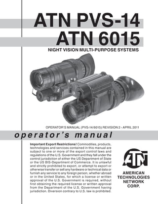
  • 1. ATN PVS-14 o p e r a t o r ’s m a n u a l Important Export Restrictions! Commodities, products, technologies and services contained in this manual are subject to one or more of the export control laws and regulations of the U.S. Government and they fall under the control jurisdiction of either the US Department of State or the US BIS-Department of Commerce. It is unlawful and strictly prohibited to export, or attempt to export or otherwise transfer or sell any hardware or technical data or furnish any service to any foreign person, whether abroad or in the United States, for which a license or written approval of the U.S. Government is required, without first obtaining the required license or written approval from the Department of the U.S. Government having jurisdiction. Diversion contrary to U.S. law is prohibited. OPERATOR’S MANUAL (PVS-14/6015) REVISION 2 - APRIL 2011 ATN 6015NIGHT VISION MULTI-PURPOSE SYSTEMS
  • 2. The information in this manual furnished for information use only, is subject to change without notice, is not to be construed as a commitment by ATN Corp. ATN Corp. assumes no responsibility or liability for any errors or inaccuracies that may appear in this book. © 2011 ATN Corp. All right reserved. Register your product warranty online at www.atncorp.com/warranty
  • 3. a SAFETY SUMMARY CAUTIONS • The ATN PVS-14 and ATN 6015 are precision optical instruments and must be handled carefully at all times to prevent damage. • Do not scratch the external lens surfaces or touch them with your fingers. • Wiping demisting shield with lens paper while wet or with wet lens paper can damage the coating. • To protect the image intensifier, keep the lens cap on the objec- tive lens when the monocular is not in use or when checked out in daylight conditions. • The IR illuminator is the light that is invisible to the unaided eye for use during conditions of extreme darkness. However, the light from the illuminator can be detected by others when using night vision devices. • If you use the rubber eyecaps for a long period of time, you may suffer skin inflammation. If you develop any symptoms, consult a doctor immediately. WARNING Do not carry batteries in pockets containing metal objects such as coins, keys, etc. Metal objects can cause the batteries to short cir- cuit and become very hot. THIS PRODUCT CONTAINS NATURAL RUBBER LATEX WHICH MAY CAUSE ALLERGIC REACTIONS. CAUTION:
  • 4. b WARNING Toxic Material The image intensifier’s phosphor screen contains toxic materials. • If an image intensifier breaks, be extremely careful to avoid inhaling the phosphor screen material. Do not allow the mate- rial to come in contact with the mouth or open wounds on the skin. • If the phosphor screen material contacts your skin, wash it off immediately with soap and water. • If you inhale/swallow any phosphor screen material, drink a lot of water, induce vomiting, and seek medical attention as soon as possible. WARNING The monocular will not be turned off automatically when flipped up. The monocular must be turned off by the power switch. WARNING The compass illuminator can be seen by others using night vision devices. WARNING Do not use contaminated eyecup or eyeguard. They must be replaced. WARNING When installing the headmount over the protective mask, be careful not to break the protective mask seal around your face.
  • 5. c EQUIPMENT LIMITATIONS To avoid physical and equipment damage when using the ATN PVS-14 and ATN 6015, carefully read and understand the following safety precautions. • The equipment requires some night light (moonlight, starlight, etc.) to operate. The level of performance depends upon the level of light. • Night light is reduced by passing cloud cover, while operating under trees, in building shadows, etc. • The equipment is less effective viewing into shadows and other darkened areas. • The equipment is less effective through rain, fog, sleet, snow or smoke. • The equipment will not “see” through dense smoke. NOTES • At operating temperatures below -20°C (-4°F), alkaline bat- teries are not recommended, as operating life will be severely reduced. Lithium-iron disulfide 1.5V AA batteries or equivalent should be used below -20°C (-4°F). • The purpose of the illuminator is to view at close distance up to 3 meters when additional illumination is needed. CAUTION • The ATN PVS-14 and ATN 6015 are a precision optical instru- ment and must be handled carefully at all times to prevent damage. • Be careful when leaving the helmet mount in the flipped up position or removing the helmet mount from the helmet, damage can result.
  • 6. i TABLE OF CONTENTS pg. SAFETY SUMMARY a CHAPTER 1. INTRODUCTION 1-1 1.1. General Information 1-2 1.1.1. Scope 1-2 1.1.2. Warranty Information 1-2 1.1.3. Technical Information 1-2 1.1.4. Nomenclature Cross-Reference List 1-2 1.1.5. List of Abbreviations And Acronyms 1-4 1.1.6. Glossary 1-5 1.2. Equipment Description 1-7 1.2.1. Equipment Characteristics, Capabilities, and Features 1-8 1.2.2. Location and Description Of Major Components 1-8 1.2.3. Equipment Data 1-13 1.3. Principles of Operation 1-15 1.3.1. Mechanical Functions 1-15 1.3.2. Optical Functions 1-16 1.3.3. Electronic Circuit Function 1-16 CHAPTER 2. OPERATING INSTRUCTIONS 2-1 2.1. Description and Use of Operator’s controls and indicators 2-2 2.1.1. Operator Controls and Indicators 2-2 2.2. Preventive Maintenance Chec ks and Service s (PMCS) 2-4 2.2.1. Preventive Maintenance Checks and Services Table 2-4 2.2.2. Resolution Check Using the TS-4348/UV Test Set 2-14 2.2.3. Inspection Criteria for Proper Image Intensifier Operation 2-16 2.3. General Information 2-21 2.3.1. Unpacking 2-21
  • 7. ii 2.3.2. Installation of Battery 2-21 2.3.3. Installation of Eyecup Or Eyeguard 2-23 2.3.4. Installation of Demist Shield 2-23 2.3.5. Installation of Sacrificial Window 2-24 2.3.6. Installation of LIF 2-24 2.3.7. Installation and Adjustment of Headmount 2-25 2.3.8. Installation of Headmount/Helmet Mount Adapter 2-27 2.3.9. Installation of Helmet Mount to Helmet 2-27 2.3.10.Installation of Headmount with Protective Mask 2-29 2.3.11. Installation of Weapon Mount 2-30 2.3.12. Installation of Compass Caution 2-31 2.3.13. Installation of 3x Magnifier 2-33 2.4. Operating Procedures 2-34 2.4.1. Hand-Held Operation 2-34 2.4.2. Head Mounted Operation 2-34 2.4.3. Helmet Mounted Operation 2-36 2.4.4. Weapon Mounted Operation 2-38 2.4.5. IR Source Operations 2-39 2.4.6. Operation with Compass 2-39 2.4.7. Operation with 3x Magnifier 2-41 2.4.8. Operation with Gain Control 2-41 2.4.9. Preparation for Storage 2-42 2.5. Operation under Unusual Condition 2-43 2.5.1. Operation in Dusty or Sandy Areas 2-43 2.5.2. Operation in Rainy or Humid Conditions 2-43 2.5.3. Operation in Salt Water Areas 2-43 2.5.4. Operation in Nuclear, Biological and Chemical (NBC) Environments 2-44 2.5.5. Operation in Laser Threat Environments 2-44 CHAPTER 3. MAINTENANCE INSTRUCTIONS 3-1 3.1. Lubrication Instructions 3-2 3.2. Troubleshooting Procedures 3-2 3.3. Operator ’s Maintenance Procedures 3-6 3.3.1. Cleaning the MUNVM 3-6
  • 8. iii 3.3.2. Headmount Maintenance 3-6 3.3.3. Neck Cord Maintenance 3-8 Appendix A. Components of End Item (COEI) and Basic Issue Items (BII) Lists A-1 Appendix B. Additional Authorization List (AAL) B-1 Appendix C. Expendable and Durable Items List C-1 Subject Index IND-1 HOW TO USE THIS MANUAL • Usage You must familiarize yourself with the entire manual before operat- ing the equipment. Read and follow all warning notices. • Manual Overview The table of contents includes the paragraph number, paragraph title, and page number. An index provides additional references to the subject contents.
  • 10. 1-2 1.1. GENERAL INFORMATION 1.1.1. SCOPE This manual provides operation and maintenance instructions for the Multi-Use Night Vision Monocular (MUNVM) ATN PVS-14 and ATN 6015 hereinafter referred to as the MUNVM. The MUNVM is a self-contained night vision device that enables improved night vision using ambient light from the night sky (moon, stars, skyglow, etc.). Model Number and basic description ATN NVM-14 and ATN 6015 – Multi-Use Night Vision Monocular Supplier American Technologies Network Corp. 1341 San Mateo Avenue South San Francisco, CA 94080 USA 1.1.2. WARRANTY INFORMATION This item shall conform to design, manufacturing, and performance requirements and be free from defects in material and workman- ship for a period of two (2) years from the date of acceptance. If item is defective, notify ATN or point of purchase contact. 1.1.3. TECHNICAL INFORMATION For technical information contact ATN Corp. directly at (650) 989-5100, or info@atncorp.com or your point of purchase contact. 1.1.4. NOMENCLATURE CROSS-REFERENCE LIST Table 1.1. provides a cross reference of common names and official terms. Except in the Appendices, the common names will be used. The official names are used in the Appendices because they reflect the provisioning nomenclature.
  • 11. 1-3 TABLE 1.1. NOMENCLATURE CROSS-REFERENCE LIST COMMON NAME OFFICIAL NOMENCLATURE Battery Battery Nonrechargeable Battery Cap Cover Battery Retainer Carrying Case Case, Infrared Equipment Carrying Case Strap Strapping Compass Compass Assembly Demist Shield Lens, Infrared Receiver Eyeguard Eyeguard, Optical Eyepiece Lens Cap Cap, Protective, Dust Headmount Headset Assembly Headmount/Helmet Mount Adapter Adapter, Headset Helmet Mount Mount, Viewer LIF Filter, Infrared Light Medium Browpad Browpad Assy, Medium Monocular Monocular Assy Neck Cord Cord, Fibrous Objective Lens Cap Cap, Protective, Dust Sacrificial Window Window, Sacrificial Shipping and Storage Case Case, Shipping/Storage Tethering Cord Clip, Retaining Thick Browpad Browpad Assy, Thick Thin Browpad Browpad Assy, Thin 3X Magnifier Magnifier Lens Assembly Weapon Mount Bracket, Mounting
  • 12. 1-4 1.1.5. LIST OF ABBREVIATIONS AND ACRONYMS AAL Additional Authorization List BII Basic Issue Items CAGEC Commercial and Government Entity Code cm Centimeters COEI Components of End Item CPC Corrosion Prevention and Control- CTA Common Table of Allowances- DA Department of the Army EIC End Item Code EIR Equipment Improvement Recommendation FM Field Manual Hrs Hours IR Infrared JTA Joint Table of Allowances lbs Pounds LED Light Emitting Diode LIF Light Interference Filter MUNVM Multi-Use Night Vision Monocular NVMPS Night Vision Multi-Purpose System MTOE Modified Table of Organization and Equipment- N/A Not Applicable NBC Nuclear, Biological, and Chemical NSN National Stock Number Pam Pamphlet PASGT Personal Armor System Ground Troops PMCS Preventive Maintenance Checks and Services Qty Quantity Recm Recommended Rqr Required
  • 13. 1-5 SF Standard Form TDA Table of Distribution and Allowances- TM Technical Manual TOE Table of Organization and Equipment- U/M Unit of Measure Vdc Volts, direct current 1.1.6. GLOSSARY BLACK SPOTS. These are cosmetic blemishes in the image inten- sifier of the MUNVM or dirt or debris between the lenses. BRIGHT SPOTS. These defects can appear in the image area of the MUNVM. This condition is caused by a flaw in the film on the microchannel plate. A bright spot is a small, nonuniform, bright area that may flicker or appear constant. Bright spots usually go away when the light is blocked out and are cosmetic blemishes that are signal induced. BROWPADS. Three hook-and-pile browpads are provided to adjust the headmount to fit different head sizes. The thin browpad (large head) comes attached to the headmount and the thick (small head) or medium browpads are stored in the carrying case. CAUTION. Condition, practices, or procedures that must be ob- served to avoid damage to equipment, destruction of equipment, or a long-term health hazard. CHICKEN WIRE. An irregular pattern of dark thin lines in the field- of-view either throughout the image area or in parts of the image area. Under the worst case condition, these lines will form hexago- nal or square-wave shaped lines. DARK (OR DARK AREA). A place in which there is very little light. It does not mean total darkness. Generally, this means conditions similar to a quarter-moon or starlit night. DARK-ADAPTED. Having ones eye adjusted to the monocular’s output under low light conditions. DIOPTER. A unit of measure used to define eye correction. Adjust- ments to the diopter adjustment will provide a clearer image in each eye.
  • 14. 1-6 EDGE GLOW. This is a defect in the image area of the monocular. Edge glow is a bright area (sometimes sparkling) in the outer por- tion of the viewing area. EMISSION POINT. A steady or fluctuating pinpoint of bright light in the image area and does not go away when all light is blocked from the objective lens of the monocular. The position of an emission point within the image area of the monocular does not move. An emission point should not be confused with a point light source in the distance. FIXED-PATTERN NOISE. This is a cosmetic blemish in the im- age area characterized by a faint hexagonal (honeycomb) pattern throughout the viewing area that most often occurs at high light levels or when viewing very bright lights. Fixed-pattern noise is in- herent in the structure of the fiber optics and can be seen in every image intensifier if the light level is high enough. FLASHING. This is a defect in the image area of the monocular. The image appears to flicker or flash. FLICKERING. See “flashing.” GAIN. This is the number of times a night vision device amplifies light input. IMAGE INTENSIFIER. An electro-optical device that detects and amplifies ambient light to produce a visual image. INFINITY FOCUS. Adjustment of the objective lens so that a distant object, such as a star or the point light on a distant tower, forms the sharpest image. INTERMITTENT OPERATION. This is a defect in the image area of the monocular. See “flashing”. IR SOURCE. This is an IR Light Emitting Diode (LED). When turned on, the IR source provides additional illumination to enhance exist- ing light conditions used only for performing nearby tasks. LIGHT INTERFERENCE FILTER (LIF). This is a light protection fil- ter for the monocular. Use of this filter will result in a slight reduction in system gain. MICROCHANNEL PLATE. A current-multiplying optical disk that intensifies the electron image produced by the photocathode.
  • 15. 1-7 NOTE. Essential information of special importance, interest, or aid in job performance. PHOTOCATHODE. The input optic of an image intensifier that ab- sorbs light energy and in turn releases electrical energy in the form of an electron image. SCINTILLATION. A faint, random, sparkling effect throughout the image area. Scintillation is a normal characteristic of the image in- tensifier and should not be confused with emission points. Scintil- lation is more pronounced under low light conditions. Also called “video noise”. SHADING. The viewed image should be a full circle. If shading is present, you will not see a fully circular image. Shading is indicative of a dying photocathode and is caused by a defective vacuum seal of the image intensifier. Shading is very dark and you cannot see an image through it. WARNING. Conditions, practices, or procedures that must be ob- served to avoid personal injury or loss of life.
  • 16. 1-8 1.2 EQUIPMENT DESCRIPTION 1.2.1. EQUIPMENT CHARACTERISTICS, CAPABILITIES, AND FEATURES The MUNVM is a hand-held, headmounted, helmet mounted, or weapon mounted night vision system that enables walking, weapon firing, short-range surveillance, map reading, vehicle maintenance, and administering first aid in both moonlight and starlight. Each unit allows for vertical adjustment (by using head strap), fore-and-aft adjustment, objective lens focus and eyepiece focus. The monocu- lar is also equipped with an IR source and a low battery indicator. The PVS-14 model equipped with a manual gain control. 1.2.2. LOCATION AND DESCRIPTION OF MAJOR COMPONENTS The NVMPS includes the items shown in Figures 1.1., 1.2., 1.3. The major components are the headmount, helmet mount, monocular, carrying case, and the shipping and storage case. a. Monocular The monocular (see Figure 1.4.) consists of various components such as an objective lens, an image intensifier (not shown), an eye- piece lens and a battery cap. The monocular also uses the accessories listed below: Demist Shield – The demist shield (Figure 1.1.) is used to prevent the eyepiece lenses from becoming fogged. Light Interference Filter (LIF) – The LIF (Figure 1.1.) is to be used at all times. For replacing the filter the container is also the wrench. The container/wrench is used to remove and replace the LIF from the objective lens. Sacrificial Window – A replaceable sacrificial window (Figure 1.1.) is supplied to protect the objective lens during operation in adverse conditions. Compass – The compass (Figure 1.2.) enables the operator to see azimuth readings in the monocular.
  • 17. 1-9 FIGURE 1.1. COMPONENTS OF NVMPS HEAD/HELMET MOUNT ADAPTER TETHERING CORD HEADMOUNT THIN BROWPAD HELMET MOUNT WEAPON MOUNT BATTERY CARTRIDGE CARRYING CASE OPERATOR’S MANUAL MEDIUM AND THICK BROW- PADS LENS PAPER CARRYING CASE STRAP SACRIFICIAL WINDOW DEMIST SHIELD EYEGUARD BATTERYNECK CORD OBJECTIVE LENS CAP MONOCULAR LIF W/ CONTAINER WRENCH
  • 18. 1-10 FIGURE 1.2. 3X MAGNIFIER AND COMPASS FOR PVS-14/6015 COMPASS 3X MAGNIFIER (ADDITIONAL ITEM)
  • 19. 1-11 FIGURE 1.3. SHIPPING AND STORAGE CASES FOR PVS-14/6015 (SEE FIGURE 1.1. FOR DETAILS) SHIPPING AND STORAGE CASE
  • 20. 1-12 FIGURE 1.4. MULTI-USE NIGHT VISION MONOCULAR OBJECTIVE LENS EYEPIECE LENS POWER SWITCH GAIN CONTROL BATTERY CAP Tethering Cord – The tethering cord (Figure 1.1.) enables the user to attach the compass or 3X magnifier to a button hole or belt loop to guard against dropping orlosing these items. 3X Magnifier – (Additional Authorized Item) The 3Xmagnifier (Figure 1.2.) is a lens assembly which can be added to the monocular to extend the operator’s observation ranges. b. Headmount The headmount (Figure 1.1.) secures the monocular to the opera- tor’s head for night viewing and provides freehand support for use with a weapon, protective mask or other purposes. It is adjustable and cushioned. The thin browpad used for large heads, comes at- tached to the headmount; the thick and medium browpads, used for smaller heads are stored in the carrying case. c. Helmet Mount This item (Figure 1.1.), secures the monocular to the Personal Ar- mor System Ground Troops (PASGT) helmet allowing freehand support for use with a weapon, protective mask and/or other pur- poses. The new helmet mount is made of a ruggedized metal. The old one is made of plastic.
  • 21. 1-13 d. Headmount/Helmet Mount Adapter This item (Figure 1.1.) is attached to the monocular to allow its use with the headmount or helmet mount. It allows mounting in front of the left or right eye. e. Weapon Mount The weapon mount (Figure 1.1.) adapts the monocular to the re- ceiver rail as configured for the modular weapon system kit. f. Carrying Case The carrying case (Figure 1.3.) is provided for transportation and protection of the monocular, headmount, battery and accesso- ries. Two slide keepers are provided for belt attachment and three D-rings for shoulder and leg strap attachment. A carrying case strap is also provided which can be attached to the two D-rings on the back of the carrying case. g. Shipping and Storage Case The NVMPS is supplied in a shipping and storage case (Figure 1.3.). 1.2.3. EQUIPMENT DATA The following tables provide information pertaining to the opera- tional, electrical, mechanical, optical, and environmental charac- teristics for the monocular. TABLE 1.2. OPERATOR ADJUSTMENT LIMITS ITEM LIMITS Diopter Focus +2 to –6 diopters Objective Focus 25 cm to infinity TABLE 1.3. ELECTRICAL DATA ITEM DATA Power Source Battery (1.5 Vdc max ea.) Battery Requirements 1 AA Alkaline or 1 AA 1.5 Vdc Lithium L91
  • 22. 1-14 TABLE 1.4. MECHANICAL DATA ITEM CHARACTERISTICS Shipping and Storage Case Size: Approx.14” X 9.5” X 8” Weight: 2.4 lbs. Carrying Case Size: Approx. 14” X 8” Monocular (see Note) Weight: 14 ounce NOTE Weight of the monocular does not include accessories. TABLE 1.5. OPTICAL DATA ITEM DATA Magnification 1.0X (3X with 3X magnifier) Field-of-View 40 (13 with 3X magnifier) Diopter Focus +2 to - 6 diopters Objective Focus 25 cm (9.8”) to infinity TABLE 1.6. ENVIRONMENTAL DATA ITEM DATA Monocular Operating Temperature -51°C to +49°C Monocular Storage Temperature -51°C to +85°C Illumination Required Overcast starlight to moonlight
  • 23. 1-15 1.3. PRINCIPLES OF OPERATION 1.3.1. MECHANICAL FUNCTIONS The mechanical functions of the NVMPS allow for differences in the physical features of individual operators and provide for operating the system. These functions include the power switch, eye relief adjustment, diopter adjustment, gain control, and objective focus. The mechanical controls are identified in Figure 1.5. FIGURE 1.5. MECHANICAL FUNCTIONS FOR THE NVMPS NOTE The gain control is not present in 6015 or PVS-14NG model. OBJECTIVE FOCUS DIOPTER ADJUSTMENT POWER SWITCH GAIN CONTROL EYE RELIEF ADJUSTMENT HIGH LIGHT CUT-OFF WINDOW IR LENS LATCH
  • 24. 1-16 1.3.2 OPTICAL FUNCTIONS The optical functions include an objective lens, image intensifier and eyepiece lens (Figure 1.6). The objective lens collects light re- flected from the night scene by the moon, stars, or night sky, inverts the image and focuses that image on the image intensifier. The im- age intensifier converts the captured light into a visible image and reinverts the image which can then be viewed through the eyepiece lens. FIGURE 1.6. OPTICAL FUNCTION DIAGRAM 1.3.3. ELECTRONIC CIRCUIT FUNCTION The electronic circuit regulates the direct current voltage from the battery to the image intensifier and IR source as required. It also monitors the output voltage of the battery and turns on a low-bat- tery indicator when the available battery voltage is 1.9 – 2.1Vdc. a. Power Source The electronic circuit is powered by one battery. b. High Light Cut-Off The monocular will automatically cut off after 70 ±30 seconds of operation in daylight or bright room light. Individual bright lights (headlights, flashlights, or other concentrated light sources) will not actuate the high light detector located on the front of the monocular. To turn the monocular back ON, turn the power switch to RESET/ OFF position and then to ON again. PHOTOCATHODE MICROCHANNEL PLATE FIBER-OPTIC INVERTER PHOSPHOR SCREEN OBJECTIVE LENS IMAGE INTENSIFIER POWER SUPPLY EYEPIECE LENS EYE
  • 26. 2-2 2.1. DESCRIPTION AND USE OF OPERATOR’S CONTROLS AND INDICATORS NOTE The MUNVM is a precision electro-optical instrument, so handle it carefully. If the equipment fails to operate, refer to the Troubleshooting Procedures in Chapter 3. 2.1.1. OPERATOR CONTROLS AND INDICATORS The MUNVM is designed to adjust for different users and cor- rects for most differences in eyesight. The controls and indicators for the MUNVM are shown in Figure 2.1., which are described in Table 2.1. Figure 2.1. Monocular Controls and Indicators NOTE The gain control is not present in 6015 or PVS-14NG model. NOTE Low battery indicator and IR source “ON” indicator are vis- ible in eyepiece lens. BATTERY POLARITY INDICATORS (HIDDEN) HIGH LIGHT CUT-OFF WINDOW OBJECTIVE FOCUS IR LENS LATCH DIOPTER ADJUST- MENT EYE RELIEF ADJUSTMENT POWER SWITCH GAIN CONTROL
  • 27. 2-3 TABLE 2.1. MONOCULAR CONTROLS AND INDICATORS CONTROLS AND INDICATORS FUNCTIONS Power Switch Controls monocular and IR source, ON or OFF. RESET/ OFF Same as system OFF. Also resets monocular after high light cut-off. ON Monocular activated. IR/ PULL Turn the knob clockwise to momentarily ac- tivate the IR source. Pull and turn the knob clockwise from the ON position to continu- ously activate theIR source. CAUTION Do not use excessive force to place the power switch into the momentary IR position. Low Battery Indicator When blinking it indicates a low battery condition with less than 30 minutes of battery life remaining. It is visible through the eyepiece just outside the intensified field-of-view. IR Source On Indicator When blinking it indicates a low battery condition with less than 30minutes of battery life remaining. It is visible through the eyepiece just outside the intensified field-of-view. Gain Control (PVS-14 only) Adjusts the system gain from a minimum value of approximately 25 to a maximum value greater than 3,000. Objective Focus Focuses objective lens. Adjusts for sharpest image of viewed object. Diopter Adjustment Focuses eyepiece lens for use without the need for glasses. Adjust for sharpest image of intensifier screen. Eye Relief Adjustment Adjusts the distance between your eye and the monocular. Latch Latch used for separation of monocular from head- mount/helmet mount adapter. Battery Polar- ity Indicators This feature, molded into the battery housing, shows the proper orientation of the battery. Some versions have a bubble molded into the top of the battery house, to show the + for proper orientation.
  • 28. 2-4 2.2. PREVENTIVE MAINTENANCE CHECKS AND SERVICES (PMCS) 2.2.1. PREVENTIVE MAINTENANCE CHECKS AND SERVICES TABLE a. General To ensure the readiness of the MUNVM, perform the preventive maintenance procedures in accordance with Table 2.2., prior to each mission. Preventive maintenance procedures include inspec- tion, cleaning, and performance of the checkout procedures. b. Warnings and Cautions Always observe the WARNINGS and CAUTIONS appearing in the table. Warnings and cautions appear before applicable procedures. You must observe the warnings and cautions to prevent serious in- jury to yourself and others, or to prevent your equipment from being damaged. c. Explanation of Table Entries (1) Item Number Column. Numbers in this column are for refer- ence. When completing Equipment Inspection and Maintenance Worksheet, include the item number for the check/service indicat- ing a fault. Item numbers also appear in the order that you must do checks and services for the intervals listed. (2) Interval Column. This column tells you when you must do the procedure in the procedure column. BEFORE procedures must be done before you operate or use the equipment for its intended mis- sion. DURING procedures must be done during the time you are operating or using the equipment for its intended mission. AFTER procedures must be done immediately after you have operated or used the equipment. (3) Location, Check/Service Column. This column provides the location and the item to be checked or serviced. The item location is underlined. (4) Procedure Column. This column gives the procedure you must do to check or service the item listed in the Check/Service column
  • 29. 2-5 to know if the equipment is ready or available for its intended mis- sion or operation. You must do the procedure at the time stated in the interval column. (5) Not Fully Mission Capable If: Column. Information in this column tells you what faults will keep your equipment from being capable of performing its primary mission. If you make check and service procedures that show faults listed in this column, do not operate the equipment. Follow standard operating procedures for maintaining the equipment or reporting equipment failure. NOTE Damaged accessory items (sacrificial window, demist shield, compass) do not cause the entire end item to be “not fully mis- sion capable”. However, the damaged item should be replaced as soon as practical to restore full capability of the system. d. Other Table Entries Be sure to observe all special information and notes that appear in your table.
  • 30. 2-6 TABLE2.2.PREVENTIVEMAINTENANCECHECKSANDSERVICESFORTHEMUNVM. ITEM NO. INTER- VAL LOCATION PROCEDURE NOTFULLY MISSION CAPABLEIF: CHECK/ SERVICE 1BeforeOpencarryingcaseandchecktheinven- toryitems 2Before/ After MONOCULAR Optical Surfaces Inspectalllenses(objective,eyepiece,IR lensandhighlightcut-offwindow)fordirt, fingerprintresidue,chips,orcracks.Ifnec- essary,cleananddrylenseswithwater andlenstissue. Scratchesorheavy scratchesthathinder visionwithmonocu- larturnedON,orif cracksarepresent. 3Before/ After BatteryCap Housing Inspectexternalsurfacesforcracksor damage.Scratches,cracks,andgouges areOKifoperationisnotaffected. Inspectbatterycompartment.Checkto makesurebatterycapispresent.Re- movebatterycapandinspectformoisture, cracks,corrodedordefectivespringcon- tacts,ando-ringpresentincap. Cracksordamagein thebatteryhousing. Capismissing,con- tactsdamaged,or corroded,o-ringis missing.
  • 32. 2-8 ITEM NO. INTER- VAL LOCATION PROCEDURE NOTFULLY MISSION CAPABLEIF: CHECK/ SERVICE 3. Cont. Before/ After BatteryCap/ Housing Cont. TurnmonocularOFFandthenONtoreen- ergizemonocular. NOTE Ifthemonocularfailsthishighlightcut-off test,itdoesnotcausetheenditemtobe nonmissioncapable.However,itshouldbe senttohigherlevelofmaintenanceassoon aspossible. Checkgaincontrolforfreemovementand operationperparagraph2.25. Knobisnotfreemoving ordoesnotvarygain. 4Before/ After MonocularInspectforcracksordamage.Scratches, cracks,chipsandgougesareOKifopera- tionisnotaffected. Cracksordamagein themonocular. 5Before/ After EyepieceLensRotatediopteradjustmenttomakesure theeyepiecelensmovesfreelyandisnot loose.Rangeisapproximately½turn. Binding,notmoving freelyortooloose. 6Before/ After EyecupInspectfordirt,dust,crackedortorneye- cup.Inspectforbent,broken,orimproper- lyfittingeyepiecelens.Ifnecessary,clean withwater. Chipsandcracksare permittedontheeye- cupretainingringsas longastheydonot interferewithinstal- lationofeyecup.
  • 33. 2-9 ITEM NO. INTER- VAL LOCATION PROCEDURE NOTFULLY MISSION CAPABLEIF: CHECK/ SERVICE 7Before/ After EyeguardInspectfordirt,dust,crackedortorneye- guard.Inspectforbent,broken,orimprop- erlyfittingeyeguard.Ifnecessary,clean withwater. Chipsandcracksare permittedontheeye- guardretainingrings aslongastheydonot interferewithinstalla- tionofeyeguard. 8Before/ After ObjectiveLensRotatefocusringtoensurefreemovement (rangeisapproximately1/3turn).Check objectivelensforchips,cracksanddents. Checktheinfinityfocuslockingringfor tightness.Checkforcracks. Focusringisbinding ornotabletomove. Chips,cracks,or dentspreventfull field-of-view,instal- lationofLIForthe abilitytofocus. Crackedorloose. 9Before/ After NeckCordand ObjectiveLens Cap Inspectforcracked,torn,ormissingob- jectivelenscap.Inspectneckcordforcut, damage,orlooseends. Re-tieendsifnecessary. Damaged.
  • 34. 2-10 ITEM NO. INTER- VAL LOCATION PROCEDURE NOTFULLY MISSION CAPABLEIF: CHECK/ SERVICE 10Before/ After ViewedImageNOTE OperatormayusetheTS-4348/UVto checkresolution(paragraph2.2.2). Refertoparagraph2.2.3.toinspectforop- erationaldefects. Flickering,flashing, edgeglow,orshad- ingisobserved. 11 Before/ After HEADMOUNT Straps/Pads NOTE Ifanyofthefollowingitemsaredamaged itdoesnotcausetheentireenditemtobe “notfullymissioncapable”.However,the damageditemshouldbereplacedassoon aspracticaltorestorefullcapabilityofthe system. Inspectforcuts,tears,fraying,holes, cracks,ordefectivefasteners. Damagecauses strapsorpadstobe unserviceable. 12Before/ After SocketInspectfordirt,dust,orcorrosion. Insertmonocularlatchintosockettoverify secureattachmentofmonoculartohead- mount.Ifnecessary,cleansocketwith water. Damaged,latch won’tlockoristoo loose.
  • 35. 2-11 ITEM NO. INTER- VAL LOCATION PROCEDURE NOTFULLY MISSION CAPABLEIF: CHECK/ SERVICE 13Before/ After EyeRelief Adjustment Presstheeyereliefadjustmentandcheck forfreemotion.Inspectfordamage. Binding,damagedor non-operationalslide mechanism. 14Before/ After HELMETMOUNT StrapsInspectforcuts,tears,fraying,holes, cracks,ordefectivefasteners. Damagecauses strapstobeunser- viceable. 15Before/ After SocketInspectfordirt,dust,orcorrosion. Insertmonocularlatchintosockettoverify secureattachmentofmonoculartohelmet mount.Ifnecessary,cleansocketwithwa- ter. Damaged,latch won’tlockoristoo loose. 16Before/ After Fore-and-AftAd- justment Pressthe2sidebuttonsonplasticmount ordepresssideleveronmetalmountand checkforfreemotion. Inspectfordamage. Binding,damagedor non-operationalslide mechanism. 17Before/ After MOUNTING ADAPTERS Headmount/ HelmetMount Adapter Inspectfordirt,dustorcorrosion. Insertintoheadmountorhelmetmount sockettoverifysecureattachment. Damaged,willnot latchsecurely.
  • 36. 2-12 ITEM NO. INTER- VAL LOCATION PROCEDURE NOTFULLY MISSION CAPABLEIF: CHECK/ SERVICE 18Before/ After WeaponMountInspectfordust,dirtorcorrosion.Damaged,willnot mounttomonocular orwillnotmountto rail. 19Before/ After ACCESSORIES CAUTION Thecoatingonthedemistshieldcanbe damagedifcleanedwhilewetorifcleaned withwetlenspaper.Cleanonlywhenthe demistshieldisdryandonlywithdry paper. Inspectfordirt,dust,scratchesordamage. Ifnecessary,cleanwhenshieldisdryand withdrylenstissueonly. Damageorscratch- eshindervisionwith monocularon. 20Before/ After LIFInspectfordirt,dust,scratchesordamage. Ifnecessary,cleanperparagraph3.2. Damageorscratch- eshindervisionwith monocularon. 21Before/ After SacrificialWin- dow Inspectfordirt,dust,scratchesordamage. Ifnecessary,cleanperparagraph3.2. Damageorscratch- eshindervisionwith monocularon.
  • 38. 2-14 2.2.2. RESOLUTION CHECK USING THE TS-4348/UV TEST SET NOTE The TS-4348/UV Test Set can be used by the operator to check the resolution of a monocular at any time. NOTE The TS-4348/UV Test Set can be used by Direct Support/Inter- mediate Level to perform the resolution testing 180 Day Serv- ice. If a system fails it must be tested on the TS-3895A/UV Test Set. NOTE Verify the resolution of the monocular using the TS-4348/UV Test Set at every opportunity. The resolution cannot be accu- rately measured without the test set. The following procedures are designed to check the performance of the image intensifier. a. Setup Before using the TS-4348/UV Test Set to set up and familia-rize yourself with its operation and the warnings and cautions associ- ated with that test equipment. NOTE • The resolution test must be performed in a darkened area. Your eyes must be dark-adapted to perform this test. Review the following test procedure before entering the dark area. • Expect cosmetic blemishes, such as chicken wire, black spots, and fixed-pattern noise, to stand out while viewing through the TS-4348/UV Test Set when it is on the high light level.This is acceptable. • The rejection of any MUNVM for cosmetic defects must be based on an outdoor evaluation and not the TS-4348/UV Test Set. b. Low Light and High Light Resolution Test Procedure Test the monocular for low light and high light resolution perfor- mance according to the following steps. (1) Place the HIGH/LOW switch on the test set to the LOW position.
  • 39. 2-15 (2) Install the LIF per paragraph 2.3.6. (3) Turn off the room light and let your eyes adjust to the dark. (4) Turn on the test set by setting the “II/OFF/III” switch to the “III” position. (5) Turn on the monocular and insert it into the test port on the test set. (6) Look through the monocular and view the projected pattern (see Figure 2.2.). If necessary, focus the eyepiece lens and then the objective lens to obtain the sharpest image. (7) The MUNVM monocular must be able to resolve Group 2, Ele- ment 2, under low light conditions to pass the test. If the MUNVM does not pass the test, return it to maintenance for repair. The op- erator must document resolution failures on the maintenance re- cord. FIGURE 2.2. TS-4348/UV TEST SET PATTERN NOTE The target shown is for example only and is not drawn to scale. GROUP NUMBER ELEMENT NUMBERS READ THIS FOR LOW LIGHT RESOLUTION FOR MUNVM READ THIS FOR HIGH LIGHT RESO- LUTION FOR MUNVM 1 1 1 1 2 2 2 3 4 5 6 5 2 3 4 5 6 6 4 2 3 4 5 6 3 2 3 4 5 6 5 1 1 4
  • 40. 2-16 NOTE For a pattern to be resolvable, three vertical bars and three horizontal bars must be visible. (8) Flip the HIGH/LOW switch to the HIGH position. (9) Again, look through the monocular and view the projected pat- tern (see Figure 2.2.). If necessary, refocus the objective lens and then the eyepiece lens to obtain the sharpest image. (10) The MUNVM must be able to resolve Group 3, Element 5, un- der high light conditions to pass the test. If the monocular does not pass the test, send it to a higher level of maintenance for repair. NOTE When using the TS-4348/UV Test Set, you are not viewing the entire image intensifier. Therefore, operational and cosmetic inspections must be done without the test set as specified in paragraph 2.2.3. (11) Look for flashing, flickering, or other nonstable behavior of the image intensifier. Also check the image intensifier for other opera- tional defects described in paragraph 2.2.3. To view the image in- tensifier under low light conditions, flip the HIGH/LOW switch to the LOW position and allow your eyes to become accustomed to the dark. If any unacceptable conditions are noted, send to a higher level of maintenance for repair. 2.2.3. INSPECTION CRITERIA FOR PROPER IMAGE INTENSIFIER OPERATION a. General As directed in the Preventive Maintenance Checks and Services table, image intensifier operation must be checked before each mission. This section provides information for the operator con- cerning what to look for, how to look for it, and how to determine if the MUNVM should be returned to the maintainer. CAUTION Perform the following inspection in the dark. To perform this inspection, attach the monocular to the headmount as described in paragraph 2.3.8. and turn the power switch to the ON position. Look through the monocular and view the image.
  • 41. 2-17 There are two groups of “defects” you may encounter – operational defects and cosmetic blemishes. Operational defects are an im- mediate cause to reject the MUNVM. Cosmetic blemishes are not a cause for rejection unless they become severe enough to inter- fere with the ability to perform the mission. The rejection of any MUNVM for cosmetic defects must be based on an outdoor evaluation and not the TS-4348/UV Test Set. b. Operational Defects These defects relate to the reliability of the image intensifier and are an indication of instability. If identified, they are an immediate cause for rejecting the MUNVM. They include shading, edge glow, flashing, flickering, and intermittent operation. (1) Shading. If shading is present, you will not see a fully circular image (see Figure 2.3). Shading is very dark and you cannot see an image through it. Shading always begins on the edge and mi- grates inward eventually across the entire image area. Shading is a high contrast area with a distinct line of demarcation. Return the MUNVM to the maintainer. FIGURE 2.3. SHADING NOTE Make sure the shading is not the result of improper eye-relief adjustment (refer to paragraph 2.4.2). (2) Edge Glow. Edge glow is a bright area (sometimes sparkling) in the outer portion of the viewing area (see Figure 2.4). SHADING
  • 42. 2-18 To check for edge glow, block out all light by cupping a hand over the objective lens. If the image intensifier is displaying edge glow the bright area will still show up. Return the MUNVM to the main- tainer. FIGURE 2.4. EDGE GLOW (3) Flashing, Flickering, or Intermittent Operation. The image may appear to flicker or flash. If there is more than one flicker, check for loose battery cap or weak battery. If weak or loose batteries are not the problem return the MUNVM to the maintainer. c. Cosmetic Blemishes These are usually the result of manufacturing imperfections that do not affect intensifier reliability and are not normally a cause for rejecting an MUNVM. However, some types of blemishes can get worse over time and interfere with the ability to perform the mission. If you believe a blemish is cause for rejection, record the specific nature of the problem on the maintenance forms and identify the position of the blemish by using the clock method and approximate distance from the center (e.g., 5 o’clock toward the outside, 2:30 near the center, or 1:00 midway). The following are cosmetic blem- ishes: (1) Bright Spots. A bright spot is a small, nonuniform, bright area that may flicker or appear constant (Figure 2.5.). Not all bright spots make the MUNVM rejectable. Cup your hand over the objective lens to block out all light. If the bright spot remains, return the MU- NVM to the maintainer. Bright spots usually go away when the light is blocked out. Make sure any bright spot is not simply a bright area EDGE GLOW
  • 43. 2-19 in the scene you are viewing. Bright spots are acceptable if they do not interfere with the operator’s ability to view the image or to perform the mission. FIGURE 2.5. BRIGHT SPOTS AND EMISSION POINTS (2) Emission Points. A steady or fluctuating pinpoint of bright light in image area that does not go away when all light is blocked from the objective lens of the monocular (Figure 2.5.). The position of an emission point within the image area does not move. Not all emission points make the MUNVM rejectable. Make sure any emission point is not simply a point light source in the scene you are viewing. Emission points are acceptable if they do not interfere with the operator’s ability to view the image or to per- form the mission. (3) Black Spots. These are cosmetic blemishes in the image in- tensifier or dirt or debris between the lenses. Black spots are ac- ceptable as long as they do not interfere with viewing the image. No action is required if this condition is present unless the spots interfere with the operator’s ability to view the image or to perform the mission. (4) Fixed-Pattern Noise. This is usually a cosmetic blemish char- acterized by a faint hexagonal (honeycomb) pattern throughout the viewing area that most often occurs at high light levels or when viewing very bright lights (see Figure 2.6.). This pattern can be seen in every image intensifier if the light level is high enough. This condition is acceptable as long as the pattern does not inter- EMISSION POINTS BRIGHT SPOTS
  • 44. 2-20 fere with the operator’s ability to view the image or to perform the mission. FIGURE 2.6. FIXED-PATTERN NOISE (5) Chicken Wire. An irregular pattern of dark thin lines in the field- of-view either throughout the image or in parts of the image area (see Figure 2.7.). Under the worst case condition, these lines will form hexagonal or square-wave shaped lines. No action is re- quired if this condition is present unless it interferes with the operator’s ability to view the image or to perform the mission. FIGURE 2.7. CHICKEN WIRE
  • 45. 2-21 2.3. ASSEMBLY AND PREPARATION FOR USE 2.3.1. UNPACKING The following steps must be accomplished prior to each mission where the MUNVM is used. CAUTION Relieve air pressure inside shipping and storage case by pressing in on opposite sides of the case before releasing latches. (1) Release the latch securing top of shipping and storage case and open. (2) Check contents for completeness (see Figure 1.1.). (3) Remove carrying case. Open carrying case (Figure 1.3.), re- move MUNVM, and check contents for completeness. (4) Inspect the monocular for obvious evidence of damage to opti- cal surfaces, body, eyecup, eyeguard, power switch, battery cap, etc. Ensure that all optical surfaces are clean and ready for use. Clean with lens paper. 2.3.2. INSTALLATION OF BATTERY CAUTION To protect the image intensifier, keep the objective lens cap on when the monocular is not in use or when using the monocu- lar in daylight conditions. The MUNVM operates with one AA battery. Battery is not supplied with the MUNVM and must be obtained separately. At operating temperatures below -20°C (-4°F), Alkaline batteries are not recommended, as operating life will be severely reduced. Lithium-iron disulfide L91 1.5V AA batteries should be used below -20°C (-4°F).
  • 46. 2-22 TABLE 2.3. ESTIMATED BATTERY LIFE BATTERY TYPE TEMPERATURE NEGLIGIBLE IR SOURCE USAGE IR SOURCE USAGE 10% OF THE TIME AA Alkaline AA Lithium L91 AA Alkaline AA Lithium L91 21°C(70°F) 21°C(70°F) -20°C(-4°F) -20°C(-4°F) 60 Hrs 70 Hrs 12 Hrs 60 Hrs 55 Hrs 65 Hrs 10 Hrs 55 Hrs CAUTION • Make certain the power switch is in the OFF position before installing the battery. FIGURE 2.8. BATTERY, EYECUP AND EYEGUARD INSTALLATION Install the AA battery into PVS14 or 6015 as follows. (1) Unscrew the battery cap. (2) Observe polarity, as indicated on the side of the battery com- partment and insert the battery. (3) Replace the battery cap and screw cap hand tight. BATTERY BATTERY CAP SACRIFICIAL WINDOW EYECUP EYEGUARD DEMIST SHIELD
  • 47. 2-23 2.3.3. INSTALLATION OF EYECUP OR EYEGUARD Perform the following procedure to install eyecup or eyeguard onto the monocular. Refer to Figure 2.8. (1) Carefully press the eyecup or eyeguard over the end of the eye- piece lens. (2) Rotate the eyecup or eyeguard into proper viewing position. Ad- just for best fit. The eyecup must seal around your eye and prevent the green glow from escaping. 2.3.4. INSTALLATION OF DEMIST SHIELD Perform the following procedures to install the demist shield on the eyepiece lens. Refer to Figure 2.8. CAUTION If the demist shield needs to be cleaned, refer to paragraph 3.3.1. for cleaning. If the demist shield is wiped while wet or with wet lens paper, you will damage the coating. NOTE If inclement operating conditions are expected to exist (e.g. significant temperature change and high humidity), install demist shield to minimize eyepiece lens fog prior to execution of mission. (1) Carefully remove the eyecup or eyeguard. (2) Carefully press the demist shield onto the eyepiece. Be careful not to smudge the eyepiece lens or demist shield. (3) Replace the eyecup or eyeguard (see paragraph 2.3.3.). 2.3.5. INSTALLATION OF SACRIFICIAL WINDOW Perform the following procedure to install the sacrificial window. Refer to Figure 2.8. CAUTION If adverse operating conditions (dust or sand) are expected to exist, attach the sacrificial window to protect the objective lens from scratches or other damage. (1) If the objective lens cap is in place, remove it.
  • 48. 2-24 (2) Carefully push the sacrificial window onto the objective lens un- til it stops. Turn the sacrificial window clockwise until it snaps into place. 2.3.6. INSTALLATION OF LIF Perform the following procedure to install the LIF onto the objective lens. FIGURE 2.9. LIF (1) Remove the container/wrench (Figure 1.3.) from the carrying case pouch. CAUTION Be careful not to touch glass surfaces. If you get fingerprints or contamination on glass surfaces, use lens paper to clean the LIF. If moisture is needed, use your breath to mist the sur- face of the glass. (2) If the objective lens cap or sacrificial window is on the objective lens of the monocular, remove it. (3) Carefully open the container/wrench and remove the LIF. Refer to Figure 2.9. (4) Hold the LIF by the ridged end (see Figure 2.9.) and thread it clockwise, into the end of the objective lens. CAUTION Do not overtighten the LIF into the objective lens. LIF RIDGES COUNTAINER/ WRENCH
  • 49. 2-25 (5) Using the ridged side of the container/wrench as a wrench, en- gage the ridges on the container with the ridges on the LIF and tighten the LIF handtight. (6) Place the empty container/wrench back into the carrying case pouch. (7) Install the objective lens cap or the sacrificial window onto the end of the objective lens and cover the LIF. NOTE The LIF must be used at all times unless directed by the unit commander, to remove the LIF, based upon his/her assess- ment of the laser threat in the theater of operations. 2.3.7. INSTALLATION AND ADJUSTMENT OF HEADMOUNT Perform the following procedures for donning the headmount. NOTE Do not don the headmount while the monocular is attached. (1) Prior to donning the headmount, loosen the four ends of the chinstrap approximately two inches from the sliding bar buckles (Figure 2.10.). (2) Snap the front and rear snaps (Figure 2.10.) in place. NOTE If the headmount is too loose, remove the attached thin brow- pad (Figure 3.3.) and replace with either the medium or thick browpad stored in the carrying case. Refer to paragraph 3.3.2. for removal and replacement of the browpads. (3) With both hands grasp the neck pad (Figure 2.10.) and pull the harness over your head and the neck pad down to the back of your neck. (4) Holding the chin cup in position on chin, adjust both sides of the chinstrap until you feel light pressure against your chin. (DO NOT TIGHTEN.) (5) Maintain the position of the chin cup and remove any slack from the chinstrap. (DO NOT TIGHTEN.)
  • 50. 2-26 FIGURE 2.10. MUNVM HEADMOUNT ADJUSTMENTS (6) Ensure that the cross-strap is not twisted and remove slack by adjusting the vertical adjustment at the neck pad. (7) Adjust chinstrap and vertical adjustment until the chin cup and headband are in a comfortable but firm position. NOTE After installing the monocular, minor strap adjustments may be necessary to achieve comfort. (8) Install the headmount/helmet mount adapter (refer to paragraph 2.3.8). (9) Refer to paragraph 2.4.2. for operating procedures. 2.3.8. INSTALLATION OF HEADMOUNT/HELMET MOUNT ADAPTER Install the headmount/helmet mount adapter (Figure 1.1.) into the monocular by aligning thumbscrew to hole and tightening as shown in Figure 2.11. There is an alignment boss on the headmount/hel- VERTICAL ADJUSTMENT (HIDDEN) NECK PAD CHINSTRAP ADJUSTMENT AND SNAP SLIDING BAR BUCKLES CHINSTRAP ADJUSTMENT AND SNAP CHIN CUP HEADBAND EYE RELIEF ADJUSTMENT HEADMOUNT SOCKET BROWPAD (THICK, MEDIUM OR THIN) CHINSTRAP ADJUSTMENT CHINSTRAP ADJUSTMENT CROSS-STRAP
  • 51. 2-27 met mount adapter that fits into a groove on the monocular. Make sure the boss on the adapter fits into the groove on the monocular. FIGURE 2.11. HEADMOUNT/HELMET MOUNT ADAPTER INSTALLATION 2.3.9. INSTALLATION OF HELMET MOUNT TO HELMET (1) Remove the helmet mount from the carrying case. Refer to Fig- ure 2.12. for helmet mount features. (2) Press the release (Figure 2.13.) to remove the mount from the helmet mount bracket. (3) Make sure the strap is laced onto the helmet mount bracket as shown in Figure 2.13. (4) With catch (see Figure 2.13.) in forward most position, place the strap over the top of the helmet center (see Figure 2.14). LATCH ALIGNMENT BOSS (HIDDEN) ALIGNMENT BOSS GROOVE THUMBSCREW
  • 52. 2-28 FIGURE 2.12. INSTALLATION OF HELMET MOUNT FIGURE 2.13. HELMET MOUNT (5) Hook the rear bracket (see Figure 2.13.) on the center of the back of the helmet and lay the strap with helmet mount bracket over the top of the helmet. (6) Hook the helmet mount bracket in the center of the front lip of the helmet and hold it in place (see Figure 2.14.). TOP EDGE OF MOUNT MOUNT RELEASE KEEPER HELMET MOUNT BRACKET STRAP MOUNT IS ROTATED 90° FOR CLARITY KEEPER HELMET MOUNT BRACKET CATCH BUCKLE LEVER STRAP REAR SNAP REAR MOUNTING HOLE REAR BRACKET NAPE STRAP
  • 53. 2-29 (7) With the buckle lever open, take up the slack in the strap using the catch. Close the buckle lever. (8) Disengage the nape strap latch on the left side of nape strap. (9) Don the helmet. Do not fasten the helmet chinstrap. (10) Engage the nape strap at the nape strap latch. Tension the nape strap for a stable fit, then install and tension the helmet chin- strap. The brow of the helmet should be parallel to the ground and the helmet stable on the head. (11) Insert the top edge of the mount under the keeper on the hel- met mount bracket and rotate downward until the latch engages (see Figure 2.14.). To release the mount from the helmet bracket, press the release and pull forward and down. FIGURE 2.14. REASSEMBLY OF HELMET MOUNT 2.3.10. INSTALLATION OF HEADMOUNT WITH PROTECTIVE MASK Perform the following procedures for donning headmount with pro- tective mask. (1) Place protective mask on your head per the instructions pro- vided with the protective mask. WARNING When installing the headmount over the protective mask, be careful not to break the protective mask seal around your face. TOP EDGE OF MOUNT MOUNT RELEASE KEEPER HELMET MOUNT BRACKET LATCH
  • 54. 2-30 (2) Install the headmount per the instructions in paragraph 2.3.7. NOTE It may be necessary to remove the browpad (Figure 2.10.) when wearing the headmount over a protective mask. 2.3.11. INSTALLATION OF WEAPON MOUNT Perform the following procedure to install the weapon mount. FIGURE 2.15. WEAPON MOUNT USAGE CAUTION The MUNVM is not a weapon sight, however, it can be used in conjunction with a collimated dot sight or laser aiming device. NOTE It is recommended that the eyecup be replaced with the eye- guard during weapon mounted use. (1) Orient the monocular and weapon mount as shown in Figure 2.15. Be sure to align the alignment boss on the weapon mount with the alignment groove in the monocular. WEAPON MOUNT ALIGNMENT BOSS (HIDDEN) THUMBSCREW CLAMPING KNOB
  • 55. 2-31 (2) Screw in the thumbscrew to secure the monocular to the weap- on mount. (3) Loosen the clamping knob on the weapon mount. Position the weapon mount with the monocular onto the weapon’s mounting rail. Tighten by turning the clamping knob. NOTE There is a ratchet in the weapon mount that prevents over- tightening of the clamp.Turn until the knob clicks. (4) Check the position of the monocular by holding the weapon in your normal firing position. Adjust the fore/aft position of the mon- ocular as necessary by loosening the clamping knob and reposi- tioning the weapon mount on the weapon’s mounting rail. 2.3.12. INSTALLATION OF COMPASS CAUTION • Use of the compass with the plastic headmount or the plastic helmet mount will result in inaccurate compass readings. The magnet cannot be removed from these mounts. • The magnet must be removed from the ruggedized metal helmet mount before installation of the compass. Failure to do so will result in inaccurate compass readings. • If the magnet is not removed, turn the ruggedized metal helmet mount in to unit maintenance for removal. See Figure 2.16. for location of magnet. NOTE • Prepare the monocular for operation. • Leave LIF in place when installing the compass. (1) If the sacrificial window or objective lens cap is in place, remove it. (2) Turn monocular on. (3) Rotate the objective lens focus completely counterclockwise (while looking through the monocular). NOTE The o-ring must be in place in the compass in order for the compass to fit properly.
  • 56. 2-32 FIGURE 2.16. LOCATING THE MAGNET FIGURE 2.17. COMPASS INSTALLATION (4) Press the compass onto the objective lens at an angle using your left hand. Slowly turn the compass counterclockwise until it is in the vertical position (with compass illumination button pointing down). See Figure 2.17. (5) Ensure that the compass fits tightly to the objective lens. (6) Refer to paragraph 2.4.6. for operation of the compass. MAGNET
  • 57. 2-33 2.3.13. INSTALLATION OF 3X MAGNIFIER The 3X magnifier can be threaded directly into the objective lens, with the LIF removed. It can also be threaded into the focus ring adapter and slipped on over the end of the objective lens with the LIF installed. Figures 2.18. and 2.19. illustrate these installation procedures. FIGURE 2.18. 3X MAGNIFIER INSTALLATION WITHOUT LIF FIGURE 2.19. 3X MAGNIFIER INSTALLATION WITH LIF THREAD DIRECTLY INTO OBJECTIVE LENS AS SHOWN 3X MAGNIFIER FOCUS RING ADAPTER STEP 1 STEP 2 THREAD 3 X MAGNIFIER INTO FOCUS RING ADAPTER
  • 58. 2-34 2.4. OPERATING PROCEDURES This section contains operating procedures for using the NVMPS as hand-held, head mounted, helmet mounted or weapon mounted monocular. Prior to operating the monocular, make certain that all the steps in 2.3.3., Assembly and Preparation for Use, have been read and performed. 2.4.1. HAND-HELD OPERATION Operate the monocular only under darkened conditions or use the objective lens cap to cover the objective lens for daylight condi- tions. NOTE When using the monocular without a mounting device, make sure to place the neck cord around your neck. (1) Ensure that the battery are installed per paragraph 2.3.2. (2) Turn the power switch to ON. NOTE The sharpest image will be observed only when the objective lens and eyepiece lens are properly focused. (3) Rotate the diopter adjustment for the clearest view of the image intensifier screen. (4) Focus the objective lens while observing an object until the sharpest image is obtained. 2.4.2. HEAD MOUNTED OPERATION Perform the following procedures for head mounted operation. CAUTION Operate the monocular only under darkened conditions or use the lens cap to cover the objective lens for daylight condi- tions. (1) Ensure that batteriy are installed per paragraph 2.3.2. (2) Don the headmount per instructions in paragraph 2.3.7.
  • 59. 2-35 NOTE To make it easier to align the monocular, eyecup, and eyepiece lens to the eye, depress the eye relief adjustment and slide the headmount socket all the way forward before attaching the monocular. FIGURE 2.20. HEADMOUNT/HELMET MOUNT ADAPTER OPERATION (3) Align the headmount/helmet mount adapter’s latch to the head- mount socket (Figure 2.20.). Press and hold down the latch lever while installing the monocular into the headmount socket. Release the latch when the monocular fully engages the socket. (4) Set your eye relief by depressing the eye relief adjustment (Figure 2.20.) and move the monocular back toward your non-do- minate eye until the eyecup comfortably seals around the eye. (5) Turn the monocular ON. (6) Readjust the vertical adjustment (Figure 2.10.) of the head- mount until the monocular is properly aligned with your eye. HEADMOUNT SOCKET LATCH EYE RELIEF ADJUSTMENT
  • 60. 2-36 NOTE The sharpest image will be observed only when the objective lens and eyepiece lens are properly focused. (7) Rotate the diopter adjustment for the clearest view of the image intensifier screen. NOTE Any readjustment of eye relief requires readjustment of the diopter. (8) Adjust the eye relief distance by pressing the eye relief adjust- ment and sliding monocular fore or aft to obtain a full field-ofview of the image. Reset the diopter adjustment for best image. (9) Adjust the objective lens focus (Figure 2.1.) while observing an object until the sharpest image is obtained. 2.4.3. HELMET MOUNTED OPERATION CAUTION Take some precaution when using/handling the helmet mount. Most damage occurs when the helmet mount is left on the helmet when not needed for immediate use. Observe the fol- lowing cautions to significantly extend the useful life of the helmet mount. CAUTION • Do not use excessive force when changing the up/down posi- tion of the MUNVM. Excessive force can break the headmount/ helmet mount adapter. • Do not drop or throw the helmet with the helmet mount attached to it. • With the monocular in the flipped up position, do not flick the monocular down by shaking the helmet. This places signifi- cant stress on the helmet mount. • All Other Services – Return the helmet and the helmet mount to unit maintenance for direct mounting of the bracket via the helmet screws. Perform the following procedures for helmet mounted operation.
  • 61. 2-37 NOTE The helmet mount provides two positions for the user to posi- tion the MUNVM. The flipped down position allows the user to position the MUNVM directly in front of the eyes. The helmet mount also allows the user to rotate the MUNVM to a flipped up position when the MUNVM is not needed for immediate use. Both the flipped down and the flipped up positions have a positive stop which assures the user that the MUNVM is in the correct position. NOTE The headmount/helmet mount adapter allows the MUNVM to be rotated from the left to the right eye or vice versa.The MUNVM can be moved to the flipped up position with the headmount/ helmet mount adapter positioned to either the left or the right. (1) Ensure that the battery are installed per paragraph 2.3.2. (2) Don the helmet mount per instructions in paragraph 2.3.9. (3) Place the monocular in the socket of the helmet mount. Set your eye relief by depressing the side buttons (or press down on side lever on metal mount) (see Figure 2.21.) and carefully move the monocular fore or aft until the eyecup comfortably seals around the eye. Readjust the helmet straps as required for vertical adjust- ment. FIGURE 2.21. TILT AND FLIP-UP ASSEMBLY MECHANISMS (4) Turn power switch to ON. Adjust the tilt by using the tilt ad- justment lock knob (or tilt adjustment lever on metal mount) (Figure 2.21.) until you obtain a comfortable viewing angle. PLASTIC MOUNT TILT ADJUSTMENT LOCK KNOB SOCKET SIDE BUTTONS (2 EA) (FORE-AND-AFT ADJUSTMENT) METAL MOUNT TILT ADJUSTMENT LEVER SOCKET SIDE LEVER (FORE-AND-AFT ADJUSTMENT)
  • 62. 2-38 NOTE The sharpest image will be observed only when the objective lens and eyepiece lens are properly focused. (5) Rotate the diopter adjustment for the clearest view of the image intensifier screen. NOTE Any readjustment of eye relief requires readjustment of the diopter. (6) Adjust the eye relief distance by depressing the side buttons (Figure 2.21.) (or press down on side lever on metal mount) and sliding monocular fore or aft to obtain a full field-of-view of the im- age. Reset the diopter adjustment for best image. (7) Adjust the objective lens focus (Figure 2.1.) while observing an object until the sharpest image is obtained. (8) To flip up, grasp the helmet tilt and flip-up assembly and rotate upward and rearward until the latch is firmly engaged. WARNING The monocular will not be turned off automatically when flipped up. The monocular must be turned off by the power switch. (9) To flip down, grasp the helmet tilt and flip-up assembly and ro- tate downward and forward until the latch is firmly engaged. (10) Turn the power switch to the ON position to resume viewing. 2.4.4. WEAPON MOUNTED OPERATION NOTE The MUNVM can be used in conjunction with a collimated dot aiming device mounted on the forward mounting rail. The brightness control for the aiming device should be set at or near it’s minimum setting. Perform the following procedures for weapon mounted operation: (1) Ensure that the battery are installed per paragraph 2.3.2. (2) Assemble the weapon mount to the monocular per paragraph 2.3.11., steps 1 and 2.
  • 63. 2-39 (3) Mount the monocular with adapter onto the M16/M4 receiver rail per paragraph 2.3.11., steps 3 and 4. (4) Rotate the diopter adjustment for the clearest view of the image intensifier screen. (5) Adjust the objective lens focus (Figure 2.1.) while observing an object until the sharpest image is obtained. 2.4.5. IR SOURCE OPERATIONS WARNING The IR source is a light that is invisible to the unaided eye for use during conditions of extreme darkness. However, the light from the IR source can be detected by the enemy using night vision devices. NOTE The purpose of the IR source is for viewing at close distances up to 3 meters when additional illumination is needed. (1) Pull the power switch knob out and rotate clockwise to the IR position. With the monocular held to the eye, observe that a red light appears in the eyepiece. This indicates that the IR source is operating. (2) For momentary IR, turn the power switch clockwise (without pulling) past the ON position. Observe that a red light appears in the eyepiece. 2.4.6. OPERATION WITH COMPASS WARNING The compass illuminator can be seen by others using night vision devices. CAUTION You will get inaccurate readings, when using the compass on any head or helmet mount with the magnet still installed. Only the magnet on the metal mount can be removed without caus- ing damage to the equipment, see paragraph 2.3.12.
  • 64. 2-40 NOTE • The compass reading is the magnetic North, not true North. • The compass reading is within 2° of correct absolute mag- netic bearing. Compass readings with mounted monocular (head mount or helmet mount) can be up to 15° of correct absolute magnetic bearing. This occurs mostly in the East (90°) to West (270°) and less in the North (360°) to South (180°) reading. If the compass is inadvertently magnetized this could cause an additional 15° error. • The objective lens focus can be fine tuned after installation, but in order to obtain an accurate reading, the compass must be vertical. (The compass image must be level.) (1) Install per paragraph 2.3.12. (2) If necessary to more clearly view your distant object, adjust the objective lens focus slightly by gripping the compass and turning clockwise. NOTE • Increase brightness slowly. Excessive brightness may burn a temporary image into the image intensifier. Do not increase brightness any more than is necessary to clearly read the compass heading. • The monocular must be focused at or near infinity for proper compass operation. FIGURE 2.22. VIEW THROUGH INSTALLED COMPASS
  • 65. 2-41 (3) To view the compass through the monocular, grip the compass with index finger on top and thumb on illumination button on bottom. Press button slowly with thumb until proper brightness is obtained. The image should appear as shown in Figure 2.22. (4) The compass readings should change when you move your head from side to side. Rotate or tap compass slightly to ensure compass is operating correctly. Hold the monocular in a level posi- tion to assure free rotation of the compass scale. (5) The tick mark closest to the center of the lighted display is the compass bearing. The tick marks are in degrees, with longer tick marks every five degrees and bearing labels every 10 degrees. 2.4.7. OPERATION WITH 3X MAGNIFIER (1) Install per paragraph 2.3.13. NOTE The mated 3X magnifier and objective lens will turn as a unit to allow focusing. (2) Grasp the 3X magnifier and focus while observing an object until the sharpest image is obtained. 2.4.8. OPERATION WITH GAIN CONTROL (PVS-14 ONLY) Turn the gain control (Figure 2.23) to balance the illumination input to the eye. FIGURE 2.23. GAIN CONTROL GAIN CONTROL
  • 66. 2-42 2.4.9. PREPARATION FOR STORAGE (1) Shutdown. Perform the following procedures to shut down the monocular. (a) Turn the monocular power switch to the OFF position. (b) Remove the monocular from the headmount, helmet mount or weapon and remove the weapon mount from the monocular. WARNING Do not carry batteries in pockets containing metal objects such as coins, keys, etc. Metal objects can cause the batteries to short circuit and become very hot. (2) Packaging After Use. (a) Remove battery cap and remove battery. (b) Inspect the battery housing for corrosion or moisture. Clean and dry if necessary. (c) Replace the battery cap. (d) Remove the demist shield or sacrificial window if installed. Install objective lens cap. NOTE • Prior to placing MUNVM into carrying case, ensure MUNVM and case are free of dirt, dust, and moisture. • The monocular and helmet mount should not be left on the helmet when the helmet is removed. (e) Refer to Figure 1.1. for proper placement of demist shield, battery, carrying case strap, lens paper, sacrificial window, manual, LIF, browpads, headmount, helmet mount, headmount/ helmet mount adapter and weapon mount. (f) Place the monocular into the shallow pocket of the carrying case. (g) Place the carrying case into the shipping and storage case, close and latch (Figure 1.3.). (h) Return to storage area.
  • 67. 2-43 2.5. OPERATION UNDER UNUSUAL CONDITIONS 2.5.1. OPERATION IN DUSTY OR SANDY AREAS CAUTION Operation in dusty or sandy areas can pit and scratch the opti- cal elements and damage the mechanical components unless the precautions given below are observed. (1) Ensure that the sacrificial window is in place over the LIF. (2) Avoid pointing the monocular into the wind unless necessary for operation. (3) Keep the carrying case closed unless removing or replacing items. (4) Ensure that all dust and sand is removed from the MUNVM and carrying case after operation. 2.5.2. OPERATION IN RAINY OR HUMID CONDITIONS CAUTION Operation in rainy or humid conditions can cause corrosion and deterioration of the MUNVM unless the precautions given below are observed. (1) Install the demist shield (paragraph 2.3.4.). (2) Keep the carrying case, and shipping and storage case closed unless removing or replacing items. (3) Dry the monocular, mounts, and accessories after exposure to rain or high humidity and before storage. This will prevent mildew from forming in the case. (4) Do not store monocular in a wet carrying case or a wet shipping and storage case. 2.5.3. OPERATION IN SALT WATER AREAS After exposure to salt water, clean the MUNVM (paragraph 3.3.1).
  • 68. 2-44 2.5.4. OPERATION IN NUCLEAR, BIOLOGICAL AND CHEMICAL (NBC) ENVIRONMENTS WARNING Do not use contaminated eyecup or eyeguard. They must be replaced. (1) Decontamination – Wear a protective mask while using MUNVM after decontamination process. (2) Hardness – Do not use DS-2 for decontaminating the MUNVM. To decontaminate, use 5% sodium hypochlorite and rinse with hot (158° F) soapy water. 2.5.5. OPERATION IN LASER THREAT ENVIRONMENTS NOTE The LIF is a light-protection filter. This filter must be used at all times unless directed by the unit commander, to remove the LIF based upon his/her assessment of the laser threat in the theater of operations. Use of this filter will result in a slight reduction in system gain. Install the LIF as described in paragraph 2.3.6.
  • 70. 3-2 3.1. LUBRICATION INSTRUCTIONS No lubrication is required. 3.2. TROUBLESHOOTING PROCEDURES 3.2.1. TROUBLESHOOTING Table 3.1. lists common malfunctions that you may find with your equipment. Perform the tests, inspections and corrective actions in the order they appear in the table. This table cannot list all the malfunctions that may occur, all the tests and inspections needed to find the fault, or all the corrective actions needed to correct the fault. If the equipment malfunction is not listed or actions listed do not correct the fault, notify your maintainer.
  • 71. 3-3 TABLE3.1.OPERATOR’STROUBLESHOOTING. MALFUNCTIONTESTORINSPECTIONCORRECTIVEACTION 1.Monocularfailstoactivate.Visual. Checkfordefective,missingor improperlyinstalledbattery. TurnpowerswitchtoRESET/ OFFpositionandthenON. Replacebatteryorinstallcor- rectly. 2.IRsourcefailstoactivate.Inadarklocationwithsystem turnedon,activateIRsource. VisuallycheckIRsourceopera- tion;sceneshouldbrighten. IfIRsourcestillfailstoactivate, refertohigherlevelofmainte- nance. 3.IRsourceindicatorfailstoac- tivate. Visual.Refertohigherlevelofmainte- nance. 4.Poorimagequality.Checkobjectivelensoreyepiece lensfocus. Checkforfoggingordirtonob- jectivelensoreyepiecelens. Refocus. Cleanlenssurfacesper paragraph3.2. 5.Lightvisiblearoundeyecup.Checkeyereliefdistance. Checkeyecupforresiliency. Readjustforpropereyerelief distance. Ifeyecupisdefective,referto higherlevelofmaintenance. 6.Diopteradjustmentcannotbe made. Checktoseeifthediopteradjust- mentisbentorbroken. Ifdamaged,refertohigherlevel ofmaintenance.
  • 72. 3-4 MALFUNCTIONTESTORINSPECTIONCORRECTIVEACTION 7.Batterycapdifficulttoopen.Visuallyinspectforthepresence ofano-ring. Checkfordamagedbatterycap. Ifo-ringismissing,refertohigher levelofmaintenance. Ifdamaged,refertohigherlevel ofmaintenance. 8.Headstrapscannotbetight- ened. Checkfordefectivebuckles,fas- tenersorstraps. Ifdamaged,refertohigherlevel ofmaintenance. 9.Headmountorhelmetmount socketandheadmount/helmet mountadapterlatchdoesnot catch. Checksocketorlatchfor dirt. Checksocketorlatchfor damage. Cleansocketandlatch. Ifdamaged,returneitherhead- mountorhelmetmountsocket andheadmount/helmetmount adaptertohigherlevelofmain- tenance. 10.Helmetmountwillnottighten tohelmet. Inspectmountinghardwarefor damage. Ifdamaged,refertohigherlevel ofmaintenance. 11.LIFwillnotthreadinorob- structview. Checkfordirtinthreads. CheckfordamagedLIF. Cleanthreads. Ifdamaged,refertohigherlevel ofmaintenance. 12.Ifdamaged,refertohigher levelofmaintenance. Visual.Refertohigherlevelofmainte- nance. 13.Compasswillnotstayonthe goggles. Visual.Refertohigherlevelofmainte- nance.
  • 74. 3-6 3.3. OPERATOR’S MAINTENANCE PROCEDURES 3.3.1. CLEANING THE MUNVM CAUTION • The monocular is a precision electro-optical instrument and must be handled carefully. • Do not scratch the external lens surfaces or touch them with your fingers. • Wiping demist shield with lens paper while wet or with wet lens paper can damage the coating. Clean monocular with water if necessary and dry thoroughly. Clean lenses with lens paper (and water if necessary, except for the de- mist shield). 3.3.2. HEADMOUNT MAINTENANCE a. Browpad Replacement Replace the browpad when cracked, torn, or contaminated. Per- form the following procedures to remove and replace the browpad. (1) Firmly grasp the headmount and remove the old browpad. (2) Gently press on the new browpad. Lightly smooth out any wrin- kles in the new browpad. b. Neck Pad Reinstallation During operation of the MUNVM, it is possible for the neck pad to become separated from its position on the headband. Perform the following procedure to reinstall the neck pad. (1) Lift the upper headband strap retention tab (see Figure 3.1) al- lowing the neck pad strap to be inserted underneath. (2) Slip the neck pad strap all the way under the upper strap reten- tion tab and then pull the lower part of the neck pad strap under the lower strap retention tab. (3) Repeat steps 1 and 2 for the other side of the headband and neckband if necessary.
  • 75. 3-7 FIGURE 3.1. REINSTALLING THE NECK PAD c. Lacing the Sliding Bar Buckles FIGURE 3.2. THREADING THE SLIDING BAR BUCKLES NECK PAD STRAP LOWER STRAP RETENSION TAB UPPER STRAP RETENTION TAB MOVEABLE SLIDING BAR FIXED SERRATED BAR
  • 76. 3-8 While donning and adjusting the headmount, it is possible for a strap to slip out of a slide fastener. Perform the following procedure to adjust the strap and sliding bar buckle. (1) Thread the strap from the inside of the buckle over the move- able sliding bar (see Figure 3.2.). Thread the strap back through the buckle but this time under the moveable sliding bar and over the serrated part of the buckle. (2) Pull the strap through the buckle and tighten as necessary. (3) Repeat steps 1 and 2 for other straps and buckles that may have come undone. 3.3.3. NECK CORD MAINTENANCE The neck cord (Figure 1.1.) may be broken, frayed, or loose at one or both ends. If loose, re-tie cord. If broken or severely frayed, install new cord as follows: (1) Insert ends through monocular holes from the rear. (2) Thread right cord end through hole in objective lens cap. (3) Tie a knot in each end.
  • 77. A-1 APPENDIX A COMPONENTS OF END ITEM (COEI) AND BASIC ISSUE ITEMS (BII) LISTS A1. SCOPE This appendix lists COEI and BII for the PVS-14/6015 to help you inventory items for safe and efficient operation of the equipment. A2. GENERAL The COEI and BII information is divided into the following lists. Components of End Item (COEI). This list is for information purposes only and is not authority to requisition replacements. These items are part of the PVS-14/6015. As part of the end item, these items must be with the end item whenever it is issued or trans- ferred between property accounts. Items of COEI are removed and separately packaged for transportation or shipment only when nec- essary. Illustrations are furnished to help you find and identify the items. Basic Issue Items (BII). These essential items are required to place the PVS-14/6015 in operation, operate it, and to do emergency re- pairs. Although shipped separately packaged, BII must be with the PVS-14/6015 during operation and when it is transferred between property accounts. Listing these items is your authority to request/ requisition them for replacement based on authorization of the end item by the TOE/MTOE. Illustrations are furnished to help you iden- tify the items. A3. EXPLANATION OF COLUMNS IN THE COEI LIST AND BII LIST Column (1), Illus. Number. Gives you the number of the item illus- trated. Column (2), National Stock Number. Identifies the stock number of the item to be used for requisitioning purposes.
  • 78. A-2 Column (3), Description CAGEC and Part Number. Identifies the Federal item name (in all capital letters) followed by a minimum description when needed. The stowage location of COEI and BII is also included in this column. The last line below the description is the CAGEC (commercial and Government entity code) (in paren- thesis) and the part number. Column (4), Usable on Code. When applicable, gives you a code if the item you need is not the same for different models of equip- ment. Column (5), U/M (Unit of Measure). Indicates how the item is is- sued for the National Stock Number shown in column (2). Column (6), Qty Rqr. Indicates the quantity required.
  • 79. A-3 FIGURE A1. COMPONENTS OF END ITEM (SHEET 1 OF 2) 10 14 1 2 3 4 5 6 7 8 9 11 12 13
  • 80. A-4 FIGURE A1.COMPONENTS OF END ITEM (SHEET 2 OF 2) 15 16 17 18 19 20
  • 84. B-1 APPENDIX B ADDITIONAL AUTHORIZATION LIST (AAL) B1. SCOPE This appendix lists additional items you are authorized for the sup- port of the PVS-14/6015. B2. GENERAL This list identifies items that do not have to accompany the PVS-14/6015 and that do not have to be turned in with it. These items are all authorized to you by CTA, MTOE, TDA, or JTA. B3. EXPLANATION OF COLUMNS IN THE AAL Column (1), National Stock Number. Identifies the stock number of the item to be used for requisitioning purposes. Column (2), Description, Commercial and Government Entity Code (CAGEC), and Part Number (P/N). Identifies the Federal item name (in all capital letters) followed by a minimum description when needed. The last line below the description is the CAGEC (in parentheses) and the part number. Column (3), Usable On Code. When applicable, gives you a code if the item you need is not the same for different models of equip- ment. Column (4), U/M (Unit of Measure). Indicates how the item is is- sued for the National Stock Number shown in column (1). Column (5), Qty Recm. Indicates the quantity recommended.
  • 86. C-1 APPENDIX C EXPENDABLE AND DURABLE ITEMS LIST C1. SCOPE This appendix lists expendable and durable items that you will need to operate and maintain the PVS-14/6015. This list is for information only and is not authority to requisition the listed items. C2. EXPLANATION OF COLUMNS IN THE EXPENDABLE/DURABLE ITEMS LIST Column (1) - Item Number. This number is assigned to the entry in the list and is referenced in the narrative instructions to identify the item (e.g. “Use lubricating oil, item 25, APPENDIX C”). Column (2) - Level. This column includes the lowest level of mainte- nance that requires the listed item (C = Operator/Crew). Column (3) - National Stock Number. This is the NSN assigned to the item, which you can use to requisition it. Column (4) – Item Name, Description, Commercial and Govern- ment Entity Code (CAGEC), and Part Number (P/N). This column provides the other information you need to identify the item. Column (5) - Unit of Measure (U/M). This code shows the physical measurement or count of an item, such as gallon, dozen, gross, etc. TABLE C1. EXPENDABLE AND DURABLE ITEMS LIST (1) ITEM NUMBER (2) LEVEL (3) NATIONAL STOCK NUMBER (4) ITEM NAME, DESCRIPTION, CAGE, PART NUMBER (5) U/M 1 C 6640-01-459-4239 PAPER, LENS (81348) A-A-50177, TYPE I, CLASS 5 PK
  • 87. IND-1 SUBJECT INDEX Pages A Abbreviations, list of .......................................................................................................1-4 Additional Authorization List..........................................................................................B-1 Adjustment (See specific adjustment.) Ambient temperature limits...........................................................................................1-2 Appendices A – Components of End Item (COEI) and Basic Issue Items (BII) Lists..................A-1 B – Additional Authorization List (AAL)....................................................................B-1 C – Expendable and Durable Items List...................................................................C-1 B Basic Issue Items List.....................................................................................................A-1 Battery AA size.....................................................................................................................1-13 Alkaline.....................................................................................................................1-13 Installing.............................................................................................................2-21 Life............................................................................................................................2-22 Lithium.....................................................................................................................1-13 Lowbatteryindicator...............................................................................1-8,1-16,2-2,2-3 Polarity Indicators.....................................................................................................2-22 Replacing.......................................................................................................2-23 Voltage............................................................................................................1-13 Black spots......................................................................................................................2-16 Bright spots..............................................................................................................1-5, 2-19 Browpads..........................................................................................1-5, 1-9, 1-12, 2-26 C Capabilities....................................................................................................................1-8 Case Carrying....................................................................................................................1-11 Shipping and Storage...............................................................................................1-11 Caution...........................................................................................................................1-5 Characteristics...............................................................................................................1-13 Checks, preventive maintenance...................................................................................2-4 Chicken wire........................................................................................................1-5, 2-20 Cleaning the MUNVM.....................................................................................................3-6
  • 88. IND-2 Compass Installation........................................................................................................2-13, 2-31 Operation .........................................................................................................2-39 Components of End Item List.........................................................................................A-1 Corrosion prevention and control...................................................................................1-4 Cross-reference list, nomenclature................................................................................1-2 D Dark(ordarkarea).............................................................................................1-5,2-14,2-34 Data...............................................................................................................................1-13 Electrical.........................................................................................................1-13 Environmental..........................................................................................................1-14 Equipment.................................................................................................................1-14 Mechanical........................................................................................................1-14 Optical...................................................................................................................1-14 Demist Shield Description...............................................................................................................1-8 Installation...............................................................................................................2-23 Destruction of materiel...................................................................................................1-5 Diopter.....................................................................................................................1-5, 1-14 Diopter Adjustment.................................................................................................1-15, 2-37 Dusty conditions...........................................................................................................2-43 E Edge glow.................................................................................................................1-6, 2-17 Electrical Function....................................................................................................................1-13 Voltage.....................................................................................................................1-13 Electronic circuit function.............................................................................................1-16 Equipment Characteristics, capabilities and features .............................................................1-8 Data.........................................................................................................................1-12 Improvement recommendations..............................................................................1-4 Expendable and Durable Items List..............................................................................C-1 Eye Relief........................................................................................................................2-3 Eyecup, installation........................................................................................................2-23 Eyeguard, installation....................................................................................................2-23 Eyepiece lens Focus........................................................................................................................1-8 Operation..................................................................................................................1-15 Range.......................................................................................................................2-8 F Features.........................................................................................................................1-8
  • 89. IND-3 Field-of-view..................................................................................................................1-14 Filter (see LIF) Fixed-pattern noise.................................................................................................1-6, 2-20 Flashing..........................................................................................................1-6, 2-10, 2-16 Flickering.........................................................................................................1-6, 2-10, 2-16 Focus Eyepiece (see Eyepiece lens) Objective (see Objective lens) G Gaincontrol.........................................................................................1-8,1-12,1-15,2-2,2-41 General information.........................................................................................................1-2 Glossary..........................................................................................................................1-5 H Hand-held operation.....................................................................................................2-34 Headmount/Helmet mount adapter installation...........................................................2-34 Head Mount Installation...............................................................................................................2-34 Maintenance.............................................................................................................3-6 Operation................................................................................................................2-34 Helmet Mount Installation and adjustment.....................................................................................2-27 Installation with protective mask.............................................................................2-27 Operation.................................................................................................................2-37 High Light Cut-Off..........................................................................................................1-16 Honeycomb (see Fixed-pattern noise) Humid conditions..........................................................................................................2-43 I, J, K Illumination required.....................................................................................................1-14 Image intensifier operation...........................................................................................2-16 Infinity focus...................................................................................................................1-6 Inspection Criteria for proper image intensifier operation..........................................................2-16 Preventive maintenance...........................................................................................2-4 Intermittent operation.....................................................................................................2-17 IR source operations....................................................................................................2-39 L Laser threat environments............................................................................................2-44 Latch........................................................................................................................2-2, 2-29 LED On Indicator.............................................................................................................1-6
  • 90. IND-4 LIF Description...................................................................................................1-3, 1-4, 1-18 Installation...............................................................................................................2-24 Lithium battery (see Battery) Location and description of major components............................................................1-8 Low battery indicator Description...............................................................................................1-8, 2-2 Operation.................................................................................................2-2 Lubrication......................................................................................................................3-2 M Magnification.................................................................................................................1-14 Maintenance Cleaning the MUNVM................................................................................................3-6 Headmount...............................................................................................................3-6 Neck Cord.................................................................................................................3-8 Mechanical data............................................................................................................1-14 Mechanical functions....................................................................................................1-15 Monocular......................................................................................................................1-8 N NBC environments.........................................................................................................2-44 Neck cord................................................................................................................1-9, 3-8 Nomenclature.................................................................................................................1-2 O Objective lens Focus................................................................................................................1-14 Function...................................................................................................................1-15 Location....................................................................................................................1-15 Operating temperature.................................................................................................1-14 Operator adjustment limits............................................................................................1-14 Operator controls and indicators...................................................................................2-2 Optical Data..........................................................................................................................1-14 Functions..................................................................................................................1-14 P PMCS.............................................................................................................................2-4 Power Source.............................................................................................................1-14, 1-15 Switch.......................................................................................................................1-15 Preparation for storage................................................................................................2-44 Purpose of equipment............................................................................................1-13