Inflatable seals work by introduction of an inflation pressure into the cavity of the inflatable seals. This inflation pressure causes the displacement of the seals effecting a positive seal between the seals and the surface to be sealed. Once the seals inflation pressure is removed the seal returns to its uninflated position
Inflatable seals work by introducing inflation pressure into their cavity, causing the seals to displace and create a positive seal against surfaces. Regulated air is commonly used as the inflation medium. Inflatable seals offer versatile configurations in radial and axial directions. They are made of silicone or other materials and can accommodate variable sealing gaps by inflating. When pressure is removed, they return to their original shape.
This document describes different types of valves and their functions, including:
- On-off valves like gate valves, plug valves, ball valves which are used to fully open or close flow.
- Throttling valves like globe valves and butterfly valves which are used to control the rate of flow.
- Check valves which allow flow in only one direction to prevent backflow.
- Pressure relief valves which open at a set pressure to relieve excess pressure and protect systems.
- Control valves and the components that are used in pneumatic pressure control systems.
Learn about the different types of engineered spring supports and when to use variable springs, constants or big tons depending on the design conditions. See how shock control, restraint and support devices are used to guide or restrain movement during normal operating conditions or under impulse loading events. Learn about pre-insulated pipe supports, including various insulating materials used for both cold and hot applications. Discover the slide plate sandwich concept and explore different slide plate materials used to reduce the coefficient of friction. View examples of expansion joints, pressure vessels, pig launchers and receivers.
The document discusses the design of vessel heads and closures. It describes various types of heads including flat heads, dished heads, elliptical heads, hemispherical heads, and conical heads. It provides equations for analyzing stress and calculating thickness for flat heads depending on their attachment method to the vessel shell. The maximum stress occurs at the edge of a flat head for a simply supported case and at the center for a clamped case.
Wire ropes are made of strands of twisted steel wires wrapped around a core. They are used to transmit power over long distances in applications like elevators, cranes, and bridges. Wire ropes have advantages like being lighter, more reliable, and durable. They are classified based on the direction of twist of the wires and strands. Design considerations for wire ropes include selecting the type based on application, calculating design load and rope diameter, and ensuring stresses do not exceed the rope's ultimate strength. Sample problems demonstrate designing a wire rope for a mine hoist and selecting a rope to lift debris from a well.
This document provides information to help identify valves, including typical markings found on ball valves. It discusses markings that indicate valve size, body material, pressure class, and casting number. It also explains how to decipher valve tag information regarding the body material, seat material, pressure rating, and trim. Additionally, it provides metric equivalents for size references and a chart showing maximum allowable pressure at different temperatures. The goal is to equip readers to identify key details about valves to determine appropriate replacements or retrofits.
1. The document provides design procedures and formulas for selecting various transmission system components from a design data book, including:
2. Procedures are given for designing flat belts, v-belts, chain drives, wire ropes, spur gears, and helical gears using steps that include selecting standard component sizes, calculating speeds and power ratings, and checking safety factors.
3. Formulas are drawn from the design data book to calculate values like belt speed and load rating, chain breaking load and bearing stress, wire rope bending load, and initial gear design torque. Standard values are then selected based on these calculations.
Method to calculate the press fit force for device as servo presses, hydraulic presses and other devices used to fit componets in automated assembly line
The document summarizes the basics of pressure relief devices, including why they are required, common components, classification and types. It provides examples of relief scenarios and causes of overpressure. The key steps in relief device sizing calculations are outlined. An example calculation is shown for checking the adequacy of installed relief devices for a reactor system during an emergency relief scenario involving an external fire.
This document outlines technical requirements for positive displacement pumps used in the petroleum, chemical, and gas industries according to API 675 standards. It covers hydraulic diaphragm and packed plunger pump designs, excluding rotary pumps. Requirements include materials of construction, pressure containment, liquid end connections, flanges, check valves, diaphragms, relief valves, gears, bearings, lubrication, capacity control, and accessories like drivers, motors, couplings and guards.
V-Belts are the most common type of drive belt used for power transmission. Their primary function is to transmit power from a primary source, like a motor, to a secondary driven unit. They provide the best combination of traction, speed transfer, load distribution, and extended service life.
Sesión técnica, sala KM 19, Epoxy pipeline technologyLTDH2013
The document provides an overview of the evolution of epoxy-based pipeline repair technology developed by British Gas in the 1980s. It describes how epoxy repair sleeves can be used to repair pipeline defects such as corrosion and cracks without interrupting product flow. Over time, the technology has been adapted to create branch connections using epoxy grouted tees and to replace pipeline sections under roads with epoxy sleeves as an alternative to heavy wall pipe. The epoxy solutions provide benefits such as eliminating on-site welding and allowing repairs without reducing pipeline pressure.
Terminology, Control Valve Basic Designs, Characterization and Trim Design, Control Valve Technical Considerations, Force-Balance Principle, Actuator Basic Designs, Control Valve Unit Action, Actuator Benchset Range, Valve Positioner Basics, Control Loop Action, Control Valve Packing Designs, Seat Leakage
This document discusses the design and manufacturing of hydraulic cylinders. It defines hydraulic cylinders as devices that convert the energy of pressurized fluid into linear mechanical force and motion. It then describes the key components of hydraulic cylinders including the piston rod, seals, guide bush, gland bush, end plug, flanges, and bleed ports. The document focuses on explaining the purpose and design considerations for each of these important parts.
ME 312 Mechanical Machine Design is the flagship course of the mechanical engineering department at DHA Suffa University. This lecture is about mechanical fasteners and non-permanent joints. The course is offered every fall by Dr. Bilal A. Siddiqui.
The document discusses the fundamentals of mechanical seals used in pumps. It describes how mechanical seals work to prevent leaks by creating a close fit between a stationary and rotating seal surface. It covers the basic components of mechanical seals including primary sealing elements, secondary sealing elements, and hardware. It also discusses seal face materials, designs, installation, operation, and ways to control the seal environment through flushing, cooling, and heating.
O-Ring is the most widely used seal because of its inexpensive production methods and its ease of use. We offer you a range of elastomeric materials for both standard and special applications which allow the O-Ring to seal practically all liquid and gaseous media.
Seals are used to prevent fluid leakage. Mechanical seals specifically use two flat faces in contact that rotate to create a tight seal against leakage. They have primary sealing faces and secondary seals. Mechanical seals come in various types classified by design and arrangement, such as single or double seals, and balanced or unbalanced designs. Proper material selection, installation, maintenance, and flushing plans are required for mechanical seals to function effectively.
A thermostatic expansion valve is built up around a thermostatic element - separated from the valve body by a diaphragm.A capillary tube connects the element to a bulb
and a valve body with valve seat and a spring. For more info, visit http://www.danfoss.in/
This document discusses materials, heat treatments, and dimensional stability of rolling bearings used in SKF bearings. The key points are:
1) Bearing rings and rolling elements are made of through-hardening carbon chromium steel or case-hardening chromium-nickel steel and manganese-chromium steel.
2) Heat treatments include bainitic hardening, case hardening, and martensite hardening, each with advantages like dimensional stability or hardness, and disadvantages like cost or risk of cracks.
3) Dimensional stability is highest in bainite-hardened materials and martensite-hardened bearings can experience the most diameter change with heat.
This document provides an overview of fundamentals of mechanical seals including:
- Historical development showing how mechanical seals replaced packing seals.
- Definitions and basic components of mechanical seals such as stationary and rotary faces.
- Classification of mechanical seals by arrangement (single, dual) and design (pusher, non-pusher).
- Factors to consider when applying mechanical seals such as pressure, temperature and fluid properties.
SINGLE STAGE CENTRIFUGAL PUMP Assembly and Maintenance Exercise PresentationSahdev Kaushik
This document provides assembly and maintenance instructions for a single stage centrifugal pump. It outlines how to install the inner and outer bearings into the bearing block, insert the keyed shaft, and assemble the bearing block housing. It also describes assembling the pump casing, impeller, packing gland unit, and shaft sleeve, and provides steps for dismantling the impeller, gland packing, bearings, and shaft.
The document is a presentation about industrial compressors used in processing plants. It discusses the main types of compressors, including positive displacement and dynamic compressors. It describes methods of capacity control for different compressor types and flow capacities at varying discharge pressures. Standard speed and flow capacity ranges for compressor drives are also covered. The presentation focuses in detail on centrifugal compressors, explaining their operation and key components like impellers and diffusers. Contact information is provided for questions.
This document provides information on selecting a V-belt drive, including defining dimensions of V-belt cross sections, standard belt types, and a 10-step procedure for selection. The procedure involves determining correction factors based on application; selecting a belt cross section based on design power and input speed; choosing pulley diameters from tables; calculating belt pitch length, center distance, and arc of contact; determining the power rating of a single belt; and calculating the number of belts needed. An example application is given of selecting a belt drive connecting a 7.5 kW motor to a fan with a 1 meter center distance available.
The document provides an introduction to materials handling. It defines materials handling as the loading, moving, and unloading of materials using tackles, gadgets, and equipment. Materials handling helps industries by improving production efficiency and reducing costs. Materials are broadly classified as gases, liquids, semi-liquids, and solids. Key characteristics of each type of material that impact handling methods are described. The document emphasizes the importance of considering an industry's materials handling needs as an integrated system.
This document provides an overview and index for a conveyor belt handbook. It describes various belt reinforcement materials and their properties, including fabrics made from polyester, nylon, cotton, and steel cord. It also discusses belt cover compounds made from materials like natural rubber, polybutadiene, styrene butadiene, and nitrile rubber that are suitable for general service, high heat, chemicals, and fire resistance. The index previews topics that will be covered in the handbook such as belt capacity calculations, power and tension, construction, pulley design, and special belt types for applications like mining.
This document discusses rubber expansion joints and their uses. The key points are:
1. Rubber expansion joints are used to prevent stresses from pipe movement due to temperature changes and vibration, and to compensate for pipe misalignment. They absorb movement to prevent buckling or separation of pipes.
2. They also serve as insulation against noise and vibration transmission between pipes and equipment.
3. There are three basic types of expansion joints described - spool type, tapered, and offset joints. Spool type joints are the most common and handle the greatest range of movement. Tapered and offset joints are used to connect pipes of unequal sizes or with some misalignment.
The Xomox® XLD lined butterfly valves have thick PFA or PTFE liners that provide resistance to permeation, extending product life and improving safety. The valves feature low torque operation enabled by an innovative sealing mechanism and bearings, allowing the use of smaller and more economical actuators. The substantial liners, live-loaded stem sealing system, improved disc design, and other features provide integrity, safety and cost advantages for the valves.
Ethylene Flexijoint PTFE expansion joints are flexible connectors designed to compensate for misalignment, expansion, contraction, vibration, and shock in process piping. They are made of virgin PTFE resin through a fluoroforming process giving them chemical inertness, wide temperature resistance, and long flex life. Flexijoints are available in sizes from 1/2" to 42" and styles include LimitLink, LimitBolt, AntiSquirm, FlexArmor, Hinged, Universal, and Gimballed to accommodate various piping needs. Common applications include use in piping, pumps, and weigh cells.
These valves have gained extensive usage in many industries including power generation, pulp and paper, refineries, chemical process, pharmaceutical/bioprocessing and pollution control.
Mechanical seals are used to prevent leakage at the point where a rotating shaft passes through a pump casing. There are several types of mechanical seals classified by their sealing method - dynamic seals include labyrinth, carbon ring, gland packing, and mechanical seals. Mechanical seals have no leakage and low power loss, making them commonly used on centrifugal pumps. API standard 682 governs the selection and operation of mechanical seals for pumps handling fluids from -30°C to 260°C and pressures from 0-34.5 bars. Key components, materials, balancing methods, and failure causes were discussed in the presentation. Steam traps are also presented as devices that discharge condensates from steam systems while retaining steam to improve efficiency.
The Linuo butterfly valve uses a triple offset design that provides tight shut off and minimal friction. As the valve begins to open, the disc moves away from the seat, resulting in less friction, wear, and torque compared to traditional butterfly valves. The triple offset design also allows the valve to achieve tight shutoff even at low pressures or reverse flow. Butterfly valves are also lighter and more economical than equivalent ball valves.
A mechanical seal is a sealing device which forms a running seal between rotating and stationary parts. They were developed to overcome the disadvantages of compression packing. Leakage can be reduced to a level meeting environmental standards of government regulating agencies and maintenance costs can be lower.
Industrial walkway covers are available in various standard sizes and colors. They are made of fiberglass reinforced plastic (FRP) and embedded with fused alumina grit for traction. Different grit sizes are available for various industrial applications. Walkway covers can be cut on site and installed using screws, bolts, or mastic on surfaces like steel, wood, concrete, or grating. They are durable, chemical resistant, and meet international slip resistance standards.
Rubber Products by Cl industrial spares-manufacturing-trading-companyISMAT
ISMAT was founded in 1981 by Ali Hussain Yakub in Sheffield, UK. It initially supplied industrial spares but has since evolved to become a tier 1 supplier of rubber and plastic components to various industries. The founder considers ISMAT not just a rubber or plastic manufacturer but an engineering company focused on innovation and developing new products to meet customer needs.
SantopSeal is a Manufacturer of Extruded Thermoplastic Elastomer Seals, Gaskets, Tubing and O-rings based in the USA. We manufacture various custom extruded profiles with superior quality according to customer requirement. We also manufacture Medical grade tubing, Food grade tubing and Peristaltic pump tubing. We meet our customer’s requirements with minimal cost, great quality and very short lead time in the market
This document provides technical specifications for Keystone K-LOK butterfly valves in series 36 and 37, including:
- Size range from NPS 2 to NPS 24, with NPS 30-36 available
- Pressure and temperature ratings up to ASME 300 and 1000°F
- Features such as blow-out resistant shafts, adjustable packing, and double offset discs
- Materials of construction including various seat, body, disc, and shaft options
- Dimensional drawings for lug and wafer style valves from NPS 2 to NPS 18.
What is and what is the function of a rubber seal
The Increasing of the speed of mechanical systems, driven by the desire for greater productivity, leads to higher operating temperatures and reduced fluid viscosities. This, coupled with higher pressures, causes an increasing tendency for fluid to leak. This leak in fuel systems that handle highly flammable solvents cannot be overlooked as there is a high probability of a fire hazard.
For this reason it has become common practice to include a safe leak path in the system design, to an escape or collection point, in order to minimize risk.
Seals prevent fluid from escaping from a hollow cylinder when a shaft penetrates the cylinder wall. Most commonly, the axis will have a rotary or linear motion. If a seal is not made for functional requirements, or installed and maintained properly, it can fail, causing fluid loss. The two main functions of a seal are to keep the fluid in while keeping dirt and debris out.
Presentation Seismosys Technologies Pvt Ltd PresentationSubramanya NA
This document provides information about Seismosys Technologies Pvt Ltd, a company that designs and manufactures vibration isolation systems. It discusses how vibration isolation systems work to reduce machine vibrations without stopping them, and the benefits this provides like reduced maintenance costs and noise levels. Spring-based isolation mounts are presented as more effective than rubber mounts at isolating vibrations and providing unlimited lifespan. Applications that could benefit from vibration isolation are also listed, such as HVAC equipment, generators, industrial machines.
The document discusses Pacific Wedgeplug valves, including:
1) Key features of Wedgeplug valves like simple construction, metal sealing surfaces, and bi-directional sealing capability.
2) Typical applications in refineries and petrochemical plants, including isolation valves in various units.
3) Design details like the plug, body, seats, bonnet, and Wedgetorque operator. Purging and flushing processes are described to enhance performance.
Ladder rung covers are available in standard lengths and widths to fit over square or round ladder rungs. They are made of fiberglass composite material with embedded grit on the surface to provide traction. They are adhered to ladder rungs using adhesive and provide a safer standing surface than round rungs. The document provides specifications on available sizes, colors, grit grades, installation instructions, maintenance, slip resistance testing, and luminance data for glow-in-the-dark models.
The Sinus Slide joint as final solution - Kaushal ParikhELSCC
You cannot avoid joints in an industrial floor. The inevitable shrinkage as a result of the drying process of the concrete must be taken up by expansion joints. Each joint is a critical area in an industrial floor. Therefore you must try to limit the quantity of joints.
Advances in Spray Dry Nozzle body sealing with C&DStuart Morgan
The document discusses advances in spray dry nozzle sealing technology. It describes the limitations of traditional radial seals, which require a gap and are prone to failure under pressure spikes. The new "Click & Dry" nozzle uses two independent compressive axial o-ring seals with no gap. This eliminates the need for expensive and troublesome backup rings to support the seal. The axial face-to-face sealing arrangement of Click & Dry can withstand far greater pressures than radial seals and has a longer service life by protecting sealing faces during assembly and cleaning. Various worldwide sealing standards limit the safe operating pressure of radial seals without backup rings, showing the advantages of Click & Dry's gap-free design.
Athmer produces automatic door seals and has done so for over 60 years. Their new Stadi family of seals has improved sound insulation, smaller dimensions, easier maintenance, and options for time delay actuation. They also produce seals for sliding and pivot doors that provide four-sided sealing against noise, smoke, drafts and smells.
Western Polyrub manufactures various types of rubber seals including rubber door seals, food quality tank door seals, autoclave and sterilizer door seals, inflatable door seals for dewaxing autoclaves, glove box isolator inflatable door seals, and general inflatable door seals. The seals are made from durable materials like EPDM, silicone, and platinum-grade rubber and are used in industries like dairy, pharmaceutical, brewing, and casting to seal doors and openings at high temperatures and pressures.
Explore the key differences between silicone sponge rubber and foam rubber in this comprehensive presentation. Learn about their unique properties, manufacturing processes, and applications across various industries. Discover how each material performs in terms of temperature resistance, chemical resistance, and cost-effectiveness. Gain insights from real-world case studies and make informed decisions for your projects.
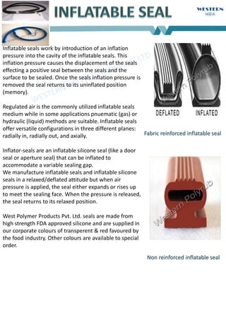
1. Inflatable seals work by introduction of an inflation
pressure into the cavity of the inflatable seals. This
inflation pressure causes the displacement of the seals
effecting a positive seal between the seals and the
surface to be sealed. Once the seals inflation pressure is
removed the seal returns to its uninflated position
(memory).
Regulated air is the commonly utilized inflatable seals
medium while in some applications pnuematic (gas) or
hydraulic (liquid) methods are suitable. Inflatable seals
offer versatile configurations in three different planes:
radially in, radially out, and axially.
Inflator-seals are an inflatable silicone seal (like a door
seal or aperture seal) that can be inflated to
accommodate a variable sealing gap.
We manufacture inflatable seals and inflatable silicone
seals in a relaxed/deflated attitude but when air
pressure is applied, the seal either expands or rises up
to meet the sealing face. When the pressure is released,
the seal returns to its relaxed position.
West Polymer Products Pvt. Ltd. seals are made from
high strength FDA approved silicone and are supplied in
our corporate colours of transperent & red favoured by
the food industry. Other colours are available to special
order.
Fabric reinforced inflatable seal
Non reinforced inflatable seal
3. Sliding doors - a great benefit for this application. The seal
automatically retracts away when air pressure is removed,
allowing the door to travel freely.
Pharma-Copia Environments - inflator-seals provide an
inflatable sealing solution where the risk of fabric
contamination is unacceptable like fluid bed dryer, processor
& coaters.
Food Processing - ideal for oven door seals. In the event of
accidental damage, the colour of the seal ensures that
detection in the event of contamination is easily achieved.
Inflatable seals are fitted in the following cases where
sealing handling, or locking is required.
Movable cofferdam bulkheads
Storage containers
Transport containers
Leaktight panels (naval, aerospacial industry)
Nuclear vessels (equipment or personnel chambers)
Isothermal chambers
Clean rooms
Sliding or quick-locking doors (autoclaves, sterilisers)
Centrifugal filters (access doors and drainage hoppers)
Aircraft access doors
Cockpit canopies
Portholes
Cofferdams
Pneumatic conveyors (bagging hoppers, valve
gates)
Phonic isolation
Inflatable Seal-Hold-It
Application
4. When free, WESTERN POLYRUB seals must not be inflated above ≥ 0,8 to1,5 bar (according to the type of the profile).
When fitted in a groove, they are perfectly leaktight for an inflation pressure of 1,25 to 1,45 times the pressure to
seal (Ps). The maximum
inflation pressure (Pi) which the seals can withstand depends on the clearance (J) between the supporting frame and the
moving panel (see profiles on pages 4-5). The inflation pressure (Pi) can be higher if clearance is reduced. seals are
designed to provide tightness on pressurised equipment. This creates a lateral force on the seal, which tends to force it
either towards the outside (equipment under pressure) or towards the inside of the equipment (equipment under
vacuum).
a)Equipment under vacuum (P0-Ps>0)
The condition of the surfaces in contact, as well as the completion of the assembly operation, make it possible for seals to
withstand a vacuum of 10-3
Torr (dynamic vacuum).
b)Equipment under pressure (P0-Ps<0)
With an internal pressure created by gas or a controlled atmosphere, the strength is directly linked to the clearances,
deformation of the contact faces and the pressurisation of the seal. In these applications, it is always necessary to
reduce dimension (J) to a minimum, restricting the surface to which the pressure of the enclosure (Ps) will be applied, in
order to reduce the radial component or, depending on the arrangement, the axial component, as far as possible as this
tends to force the seal outwards. Generally, the ratio Ps-Po/Pi is of 0,7 to 0,2 but with the limits laid down in the table
concerning profiles (pages 4-5).
MANUFACTURE
Inflatable seals are made by joining together extruded or moulded sections. This connection is made in our workshops,
which ensures perfect continuity while at the same time reducing any stresses in the joint to a minimum.
This method provides substantial flexibility with regard to the geometry of the sections. There are t w o types of standard
profiles and a series of special profiles that are used in numerous applications, i.e. sealing, locking or gripping during
automatic handling have beencreated.
For specific uses which need reinforced manufacturing (textiles, hight performance aramid fibers) or expanded profiles, see pages 12
and 13 and please contact our technical department.
seals have no textile reinforcement or expansion system. Their expansion, like their retraction, is obtained
through the combined effects of the walls of the seal forming elastic arms. The seals, which are produced
from elastomers with a high modulus of elasticity and considerable elongation and fitted in grooves, are
restricted to low work rates. As a result, they are protected against risks of bursting, so it is necessary to
observe the fitting dimensions (table, pages 4-5).
Comment: inflatable seals must be captive in slots or grooves closed on all four faces in accordance
with the specified dimensions. You are strongly recommended not to pressurise or use the seals
when one of the faces
of the groove is open. On the other hand, seals can be secured by their base and work freely. However, the
maxi- m u m pressure cannot be applied until their contact face (toothed side) is against the item to be sealed.
CEFIL’AIR®
HP
Pi
Pi
CEFIL’AIR®
LP
Outside
Pressure
(Po)
Outside
Pressure
(Po)
Pressure
to seal
(Ps)
2
9. TYPES OFELASTOMERS
WESTERN POLYRUB inflatable seals are produced with elastomers with high mechanical properties.
Silicone, SBR and EPDM are the most commonly used. Although these are high performance
materials, they are not suitable for all applications, and consequently, other elastomers should be
used.
*Profiles not kept in stock, produced on special request. (Please contact our technical department).
Note :This information represents broad outlines for use. For specific applications, please contact our technical department.
Elastomers Ref. Δ Sh A
Temp.
range
°C Properties
Good resistance to:
-water
SBR
Styrene Butadiene
Rubber 1 A60 60
–20
+100
-demineralized water
-air
-diluted acids andbases
-ketones
Abrasion-resistant
Same as SBR, with better resistanceto:
CR*
Chloroprene
4 B61K 60 –20
+110 -ultraviolet rays
-ozone
Low resistance to grease
Good resistance to:
IIR*
Butyl
5 B60 65 –20
+120 -dilutedacides and bases
-ketones
- very lowpermeability
Good resistance to:
EPDM*
Ethylene
Propylene
6 B65 65
–30
+150
-water
-steam
-atmospheric conditions
Low resistance to hydrocarbon
Good resistance to:
VMQ
Silicone
BIO-GUARDIAN®
C65 M 60 –60
+220
- dry and humid heat
- steam P ≤ 6 bars
-cold
-very low oil resistance
- does not age
FVMQ*
Fluorosilicone CF 65 M 60
–50
+200
Same as Silicone, with better resistance
to:
-aromatic hydrocarbons
-chlorinated solvents
Good resistance to:
NBR*
Nitrile Rubber 3 B 70
–30
+110
-oils
-greases
-fuels
- some solvents
HNBR*
Hydrogebated
Nitrile Rubber
3 H 70
–40
+160
Same as NBR, with better resistance to:
ozone
high temperatures
Good resistance to:
FKM* (VITON®)
Fluorocarbon
3 E65 65 –20
+180
-chlorinated solvents
-aromatics
3
10. Type with retractedend
Flange or retainingplate
Type with expandedend
PROFILES STANDARDS HP
Ref.
Nr.
silicone
Ref.
Nr.
SBR
A xB H
2
H
3
L N
339 10035 16 x12 15 13 16 5
347 10036 16 x18 21,5 19,5 16 5
356 10041 22 x19 22,5 20,5 22 6
443 10039 26 x19 23,5 20,5 26 7
405 10042 27 x21 26 23 27 7
627 10175 35 x26 34 29 35 9
369 10217 35 x32 45 35 35 9
415 10102 6,5 x5 6,5 5,5 6,5 2
512 --- 14 x10 13 11 14 5
639 --- 16 x14 17,5 15,5 16 4
603 10177 20 x20 24 21,5 20 5
514 10331 21 x24 29 26 21 6
529 --- 54 x40 48 42 54 14
PROFILES STANDARDS BP
Ref.
Nr.
silicone
Ref.
Nr.
SBR
A xB H
2
H
3
L N
921 10152 30 20 25 22 20 15
704 10118 40 27 35 29 25 20
736 10211 60 35 50 38 40 30
828 10126 90 55 75 60 60 45
--- 10094 130 70 100 80 80 65
--- 10170 150 80 110 90 100 80
N
L
H
2
N
H
3
H
3
L
END PLUGS
Linear seals may be manufactured with “solid” end plugs. In this case, the plugged areas are neutralised, as
neither expansion nor contraction can occur.
Two constructions are possible: either by plugging the expanded seal or by plugging the retracted seal. When
using either solu- tion, it is necessary to provide flanges or end plates to hold the seal in order to prevent
tearing caused by seal expansion (see flanges or retaining plates below).
Note : The dimension N represents the intermediate part be- tween
the active seal and the end plug which cannot come into contact
with the face to be sealed. The efficiency of the seal is only obtained
beyond L + N.
These parts must not be outside of the support face seals under any
circumstances.
11. Examples :
PLEASE CONSULT OUR TECHNICAL DEPARTMENT
DEFINITION OF SEAL ACCORDING TODIRECTION
AXIAL EXPANSION (LAYOUTI)
The working pressure Pi is normal.
INTERNAL RADIAL EXPANSION (LAYOUTII)
The working pressure Pi is 20 to 30% greater than the normal pressure.
EXTERNAL RADIAL EXPANSION (LAYOUTIII)
The working pressure Pi is normal or 15 to 25% higher.
J
A1
Pi
B1
J
B1
Pi
A1
A1
J
B1
Pi A1
J
B1
Pi
J/2
0,5
0,5
B1
A1 +1 Pi A1 +1
J/2
0,5
0,5
B1
Pi
END PLUGS
For specific applications requiring expansion nearly all along the seal, EXPANDABALE end plugs are available
upon request.
The circular layouts I, II and III are also applicable for formed seals if the radius RgA, RgE and RgI are followed (see pages 4 & 5).
12. SPECIAL FITTINGS
We offer a wide range of solutions. Please
contact our Technical Department for more
information.
Notes:
- during the assembly of RJO fitting, it is
important to secure the O-ring (chamfers
30°, smooth edges, etc.).
- RES fitting is only available in rubber.
STANDARD VALVES
REF
REL
REP
RJO
FITTINGS AND VALVES
Our standard fittings and valves are manufactured in brass.
We also produce fittings in any other material, such as bronze, stainless steel and elastomers.
STANDARD FITTINGS
REC
CVL
RED
REB
with non return valve
with non return valve without non return valve
RED elbow fittings and REB fittings can only be fitted on CVL valves and on REF valves 7,65x0,79.
RER
RES
ØE 4 6 8 10 12
M M6 M8 M10 M12 M14
ØJ 1,5 3 5 6 6
K 12 16 16 20 20
L 30/35
40/50
30/35/
40
50/50
40/45/
50
60/70/
80
40/50/
60
70/80/
90
50/60/70
80/90/10
0
Sx R 5x6 6x6 8x8 10x8 11x8
M M4 M6 7,65x0,79 M8 1/8 G M10 1/8NPT M12 1/4 G M14 M16
ØJ 1,2 3 3 3 5 5 5 6 6 6 8
L
15/20/2
5
30/35/4
0
50
15/20/2
5
30/35/4
0
50
20/25/
30
35/40/
50
60
15/20/
25
30/35/
40
50/60
20/25/
30
35/40/
50
60/70
20/25/
30
35/40/
50
60/70
20/25/
30
35/40/
50
60/70
20/25/
30
35/40/
50
60/70
20/25/
30
35/40/
50
60/70
30/35/40
45/50/60
70/80
40/45/
50
60/70/
80
90/100
Sx R 3x4 5x6 6x6 6x8 8x8 8x8 8x8 10x8 10x8 11x8 13x10
ØE 4 6 8 10 12 14 16
ØJ 1,5 3,4 3,4 5 6,8 6,8 8,5
L
15/20/25
30/40
15/20/2
5
30/35/4
0
50
20/25/
30
35/40/
50
25/30/
35
40/45/
50
60
30/35/
40
45/50/
60
70
35/40/
45
50/60/
70
80
45/50/
60
70/80/
90
M M10 M12 M14
ØJ 3 5 7
dxD 4x6 6x8 8x10
L 50/60/
70
50/60/7
0
80
60/70/
80
90
SxR 8x8 10x8 12x8
ØE 4 6 8 10 12 14
ØJ 1 3 5 7 9 11
d x0 2x4 4x6 6x9 8x10 9x12 11x14
L 25 35 50 60 75 85
ØE 6 7 8
ØJ 3 3 3
L minimum lengths of 200 mm (by multiple of 100 mm)
ØT
1 4 6 8 10 12 14
ØT 4H8 6H8 8H8 10H8 12H8 14H8
ØJ 1 1,5 2 4 5 6,8
BETN° 11018 15001 15004 15006 15007 15008
K 2 2 4 5 5 6
L
15/20/25
30/40
15/20/25/30
35/40/50
15/20/25/30
35/40/50
20/25/30/5
40/45/50/60
25/30/35/40
45/50/60/70
35/40/45/50
60/70/80
8
13. POSITION OF FITTINGS ANDVALVES
Inflatable seals conception requires that connections be located at the bottom of the grooves or at the
end of the seals (straight length). When seals have curves radii it is preferable to avoid connections located in the
curved area. If the equipment around the seal for assembly or other reasons requires a lateral supply, it is possible to
use elbow fittings or special constructions (please consult our technical department).
OVERMOULDED CONES
OVERMOULDED CONES (standardsizes)
ØnØ m h
h+
1
Ø+
1
Housin
g detail
Seal
detai
l
Ø Ø 4 4 6 8 10 12 14 16 18
m 6 8 12 14 21 24 26 28 30
n 5 6 10 12 14 16 18 20 22
h 3 4 6 6 10 10 12 12 12
Note : For REC, REF, REP fittings, and CVL valves, please consider the size of the thread part (M) as the connection
diameter (see sketches on page 7). In case of intermediate value (dimensions in inches), take the next larger cone. (For
other sizes, please con- tact our technical department).
ASSEMBLYCONDITIONS
For a maximum binding (metal/rubber), the fitting
valves are
equipped with a overmoulded rubber cone in
accordance to their diameters (see table below).
SURFACEFINISH
The mean roughness obtained by machining (lathe,
mill, etc.) must not be less than the value of 0,8 to 1,6
microns Ra (L.C.A. Rugotest, standard N6 - N7).
Applications where high performances are not
required, 3,2 microns Ra are permissible (standard N8,
L.C.A. Rugotest). Transverse scratches and local
damage to the bearing surfaces to be sealed are
prohibited.
PREPARATION OF GROOVESAND
CONTACTFACE
Before installation, it must be verified that the
groove taking the seal is free from roughness
(grit or weld spat- ter, flash or projections sharp
edges). If roughness occurs, this must be taken
off before the installation, followed by
degreasing with a suitable solvent.
INSTALLATION
1/ - The seal must be absolutely free from internal
pressure at the time of fitting. If the valve is equipped
with its mechanism, this must be removed during
installation.
2/ - The installation of the seal in the groove must start, by
position- ing the pressure connexion (fittings or valves)
in the (in) housings, then, the mechanical fixing is
operated. It is important to make sure that splice
vulcanisation is located far from the curve area.
3/ In order to fit the seal correctly, it is necessary to
pressurise it immediately after positioning it in the
glued groove, while observing the operation
recommendations, i.e. perfectly captive on its four faces.
4/ It is possible to leave the CEFIL’AIR®
seal pressurised
throughout the time necessary for drying or vulcanizing
the adhesives ; it is also possible, after a short drying
time, to retract it in order to complete the setting
operation. However, it must only be moved after the
bond is completely fixed.
14. Gluing
area
Gluing
area
HP
LP
ASSEMBLYCONDITIONS
FIXING THESEALS
Although inflatable HP seals can be fitted in grooves without any form of retention, it is preferable to glue
them to the bottom of the grooves. For this operation, it is recommended to use our general-purpose
adhesive which can be applied directly to the metal when it has been thoroughly degreased and is free from
rust or scale. For intensive utilizations of inflatable seals, we advise to prepare the support by a sanding
process and to use the sticking primary (i.e. PM 820) and the silicone (RTV). If a different product than the one
recommended is used, please check the instructions manual.
HP seals must be secured by the
part opposite that of the seal
(bottom
of groove only), avoiding the
use of adhesives on the
lateral parts.
LP seals will preferably be
fixed mechanically, but, if
an adhesive is necessary,
the gluing must be limited
to the foot of the profile.
FIXING THE PRESSURECONNECTION
The housing hole needs to have a conical part
according to indications on page 9, to receive the
overmoulded rubber cone of the seal. In the case of
threaded connections (REC, REF, REP, CVL) tightening
must be moderate and during this operation it is
absolutely necessary to maintain the connection in
order to avoid damaging the link between metal and
rubber. It is important not to apply any torque to the
fitting.
15. EXAMPLE OFCALCULATION
For a seal with profile N° 347, with a diameter of
1500 m m and used at an internal pressure Pi of 2 bars
Air collector
Pressure relief valve
filter
Non return
valve
Pressure
gauge
Valve
Fj = (Pi x Kj) x LD
Fj = (Pi x Kj) x µ Ø (1)
= (2 x 1,2) x (3,14 x 150 cm) = 1.130 da.N
Ø 512 339 347 356 443 405 627 369 415 639 603 514 616 921 704 736 828 1009
4
1017
0
Kj 1,0 1,2 1,2 2,0 2,2 2,3 3,0 3,0 0,7 1,2 1,6 1,6 5,0 0,8 1,5 2,5 3,0 4,2 5,0
Pi 4 4 4 6 6 6 8 8 1 5 6 7 10 3 3 3 3 3 3
CD
E
AB
PRESSURESUPPLY
Inflatable seals can be supplied either with gas or fluids. However, it is necessary to provide a constant supply, which
must be guaranteed by a pressure regulator to avoid overpressure. Due to the relative permeability of elastomers (when
inflated with air or gas) notably for silicone, it is necessary to provide pressure regulation for this type of inflation. It is
also possible to use fluids (water, oil, etc.) to prevent elastomer gas permeability. (Please contact our technical
department).
Pi = Internal pressure of the seal in
bar LD = Expanded length of the
seal in cm Kj = Coefficient of unit
contact surface
CALCULATIONS AND SUPPLY
APPLICATION FORCE (CALCULATIONS)
seals are retracted even with a residual internal pres- sure.
Their expansion occurs above the latter and brings the
contact and sealing face against for the moving part. The
pres- sure necessary for expansion varies a little over a
whole range of arrangements and depending on the
profiles used. In the majority of cases, the minimum
operating pressure is 1,5 bar.
The inflation of the CEFIL’AIR® seal provides an application
force proportional to a unit contact surface. The total
applied load (Fj) for the seal on the moving panel will be
determined by:
(1) mean
diameter
Fj
Pi
16. EXAMPLES OF APPLICATION :“Sealing”
MOBILE BULKHEAD
SEALING
WITH PROFILE REF.514
SEAL ON ISOTHERMAL
BULKHEAD SEALING
WITH PROFILE REF.369
COFFERDAM SEALING
WITH PROFILE REF.10094
STERILISER
DOORSEALING
WITH PROFILE REF.369
NUCLEAR POWER
STATION SEALING DOOR
WITH PROFILE REF.10093
EXAMPLES OF APPLICATIONS :“Handling”
Inflatable seals can also be used for the moving, handling, holding or clamping, particularly
for fragile or complex geometry objects. (see following sketch).
TO LIFT TO PRESSTO HOLD TO CLAMP
17. OTHER EXAMPLES OFPROFILES
21
18
35
27
16
20
23,5
16 26 30
35
18
2051 2190 1856 372 1406 2239
25
60
33
70
17,5
14,5
17,5
20
34
25
24
58
OTHER EXAMPLES OFAPLICATIONS
SMALL DIAMETER
Principle
END PLUGS FORTUBE
Example :“Mechanical
expansion”
Locking onshaft
Application :Handling of cylindrical
pieces
Ø 28,510
Ø 27
Examples :
Locking onshaft
(cartridge mounting
“minimum height
occupied“)
Hole tightening
Application :
Handling hollow
pieces (tube, bottle,
etc.)
Ø 23,8
Ø 29
M8
34
DATA OR SPECIFICATIONS WITH RESPECT TO ANY CUSTOMER’S PARTICULAR APPLICATIONS. USE OF THE TECHNICAL DATA OR SPECIFICATIONS
CONTAINED HEREIN WITHOUT THE EXPRESS WRITTEN APPROVAL OF TECHNETICS GROUP IS AT USER’S RISK AND TECHNETICS GROUP EXPRESSLY
DISCLAIMS RESPONSIBILITY FOR SUCH USE AND THE SITUATIONS WHICH MAY RESULT THEREFROM.
TECHNETICS GROUP MAKES NO WARRANTY, EXPRESS OR IMPLIED, THAT UTILIZATION OF THE TECHNOLOGY OR PRODUCTS DISCLOSED HEREIN
WILL NOT INFRINGE ANY INDUSTRIAL OR INTELLECTUAL PROP- ERTY RIGHTS OF THIRD PARTIES.
TECHNETICS GROUP IS CONSTANTLY INVOLVED IN ENGINEERING AND DEVELOPMENT. ACCORDINGLY, TECHNETICS GROUP RESERVESTHE RIGHT
TO MODIFY, AT ANY TIME, THE TECHNOLOGY AND PRODUCT SPECIFICATIONS CONTAINED HEREIN.
ALL TECHNICAL DATA, SPECIFICATIONS AND OTHER INFORMATION CONTAINED HEREIN IS DEEMED TO BE THE PROPRIETARY INTELLECTUAL
PROPERTY OF TECHNETICS GROUP. NO REPRODUCTION, COPY OR USE THEREOF MAY BE MADE WITHOUT THE EXPRESS WRITTEN CONSENT OF
TECHNETICS GROUP.
1812 1263 10266 10410 811 2104
18. TEL:COMPANY:
CONTACT: EMAIL:
ADDRESS: DATE:
ENDUSER:
INSTALLATION
LOCATION:
REF: ACTIVITIESFIELD:
N° CLIENT:
Slanting
Function Needed Sealing or Handling
Pressure to seal* daN
Vacuum Atmosphere
(°C)Workingtemperature*
Media*
Gas Liquid Vacuum
per Hr.or per Days or perMonths
Working cycles
nbr
Inflating duration
Deflatingduration
Sec. or
Sec.or
Min. or
Min.or
Hours or
Hoursor
Days or
Daysor
Weeks or
Weeks or
Round corner configuration Axial expansion
Mean length A0
Mean width B0
Mean Radius R0
Valve positionC0
ClearanceJ
Round corner configuration Internal radial expansionCircular
Axial expansion
Mean Diameter D0 / Dg
ClearanceJ
Length A0 / Ag
Width Bo / Bg
Radius R0 / Rg
Valve positionC0
ClearanceJ
Round corner configuration External radial expansionDiameter D0 / Dg
ClearanceJ
Diameter D0 / Dg
ClearanceJ
Length A0 / Ag
Width Bo / Bg
Radius R0 / Rg
Valve positionC0
ClearanceJ
Straight lengthSquare right angle corners
Axial expansion LengthA0
Valve positionC0
ClearanceJ
Mean length A0
Mean width B0
Valve positionC0
Angles dimensions D0
ClearanceJ
Retracted end plug
Expandable end plugs
Expanded end plugs
Valve (Information requested for any enquiry)
Material:
Type : Size:
Stainless Steel
Diameter: Lc (RER):
CVL+REB CVL+RED
Quantities:
Spot Order:
YearlyOrder:
Circular
Internal radial expansion
Circular
External radial expansion
Brass Rubber (RES only) Other:
LengthL:
WORKING CONDITIONS (Information requested for anyenquiry)
New assembly or modifiable conception or Existent not be change*
Assembly position Hoizontal Under cover Vertical
Months or
Months or
Year
Year
CONFIGURATION (Information requested for any enquiry) - dimensions in millimeter. Please provide drawing
Bottom groove cotation (Ag, …g, …) Face to seal cotation (A0, …0, …)
WESTERN POLYRUB APPLICATION DATA SHEET
Tel:91-22-
26764144/26760203/66944301/66949199
Email: info@westpolyrub.com
Bars or Global Load Expected*
RJO REF
ADDITIONAL DETAILS
REP REC CVL CVL+RED+REB RER RES
Bottom groove Face toseal
ENQUIRE US: