This document is an industrial training report submitted by Naman Mishra to Bharat Coking Coal Limited (BCCL). BCCL is a subsidiary of Coal India Limited that operates coal mines and washeries in India. The report provides an overview of BCCL and its Central Excavation Workshop in Sinidih, which repairs and maintains heavy earthmoving equipment. It also describes the main engine brands serviced at the workshop, and includes an index of topics to be covered in the report such as types of engines, diesel engine parts and their functions, engine disassembly, and transmission systems.

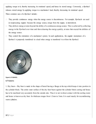
![1.ENGINE:-
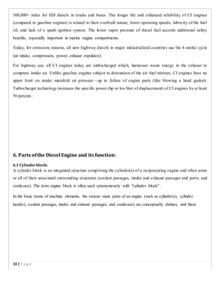
An engine is a machine designed to convert energy into useful mechanical motion. Heat engines,
including internal combustion engines and external combustion engines (such as steam engines) burn a fuel
to create heat which then produces motion.
"Engine" was originally a term for any mechanical device that converts force into motion. Most mechanical
devices invented during the industrial revolution were described as engines—the steam engine being a notable
example.
In modern usage, the term engine typically describes devices, like steam engines and internal combustion
engines, that burn or otherwise consume fuel to perform mechanical work by exerting a torque or linear force to
drive machinery that generates electricity, pumps water, or compresses gas. In the context of propulsion
systems, an air-breathing engine is one that uses atmospheric air to oxidise the fuel rather than supplying an
independent oxidizer, as in a rocket.
When the internal combustion engine was invented, the term "motor" was initially used to distinguish it from
the steam engine—which was in wide use at the time, powering locomotives and other vehicles such as steam
rollers. "Motor" and "engine" later came to be used interchangeably in casual discourse. However, technically,
the two words have different meanings. An engine is a device that burns or otherwise consumes fuel, changing
its chemical composition, whereas a motor is a device driven by electricity, which does not change the chemical
composition of its energy source.[3]
A heat engine may also serve as a prime mover ,a component that transforms the flow or changes in pressure of
a fluid into mechanical energy.
An automobile powered by an internal combustion engine may make use of various motors and pumps, but
ultimately all such devices derive their power from the engine. Another way of looking at it is that a motor
receives power from an external source, and then converts it into mechanical energy, while an engine creates
power from press.
10 | P a g e](https://image.slidesharecdn.com/anindustrialtrainingreport-190719044450/85/Industrial-training-report-Sinidih-Workshop-10-320.jpg)
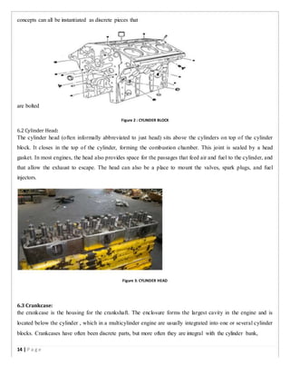
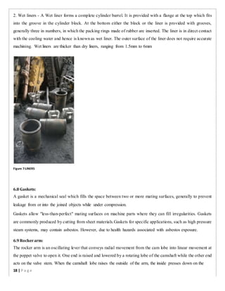
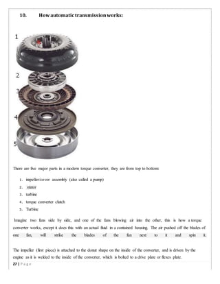
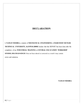
![Figure 9: EXHAUST MANIFOLD WITH TURBOCHARGER
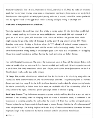
6.12 Water Pump :
A centrifugal pump is a rotodynamic pump that uses a rotating impeller to increase the pressure and flow rate of
a fluid. Centrifugal pumps are the most common type of pump used to move liquids through a piping system.
The fluid enters the pump impeller along or near to the rotating axis and is accelerated by the impeller, flowing
radially outward or axially into a diffuser or volute chamber, from where it exits into the downstream piping
system. Centrifugal pumps are typically used for large discharge through smaller heads.
Centrifugal pumps are most often associated with the radial-flow type. However, the term "centrifugal pump"
can be used to describe all impeller type rotodynamic pumps[4]
including the radial, axial and mixed-flow
variations.
6.13 Oil Filters:
An oil filter is a filter designed to remove contaminants from engine oil, transmission oil, lubricating oil, or
hydraulic oil.
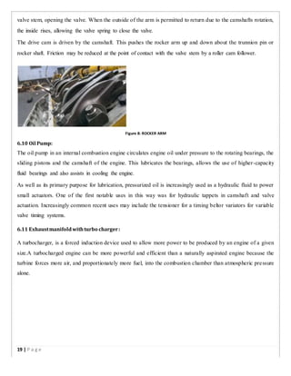
6.14 Sump:
The bottom half of the crankcase is called the oil pan or sump. It is bolted or screwed to the lower flange of the
main casting of IC engine and usually is made of pressed steel or aluminium. Oil pan serves as the reservoir for
the storage,cooling and ventilation of engine lubricating oil.
The plane of the joint between the crankcase and the oil pan may be either on the level of the crankshaft axis or
it may be lower. If it is on the level of the crankshaft axis, it will increase the bottom oil pan portion. If it is
lower than this axis, it will increase upper portion of the crankcase thus increasing rigidity..
20 | P a g e](https://image.slidesharecdn.com/anindustrialtrainingreport-190719044450/85/Industrial-training-report-Sinidih-Workshop-20-320.jpg)
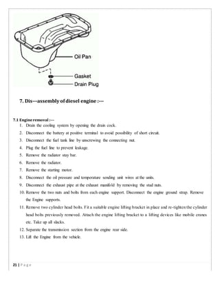
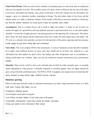
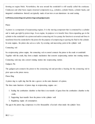
![Transmission:
Transmission is the act of passing something on in another place. A machine consists of a power source and a
power transmission system, which provides controlled application of the power. Merriam-Webster
defines transmission as an assembly of parts including the speed-changing gears and the propeller shaft by
which the power is transmitted from an engine to a live axle.[1]
Often transmission refers simply to
the gearbox that uses gears and gear trains to providespeed and torque conversions from a rotating power source
to another device. T he transmission generally is connected to the engine crankshaft via a flywheel and/or
clutch and/or fluid coupling. The output of the transmission is transmitted via driveshaft to one or more
differentials, which in turn, drive the wheels.
The workshop deals with the following series of automatic transmission:
1. CLBT-754
2. CLT-74
3. D15TR
4. D355
5. HD-78-2
6. D15 TC
An automatic transmission that selects an appropriate gear ratio without any operator intervention. They
primarily use hydraulics to select gears, depending on pressure exerted by fluid within the transmission
assembly. Rather than using a clutch to engage the transmission, a torque converter is placed in between the
engine and transmission. It is possible for the driver to control the number of gears in use or select reverse,
though precise control of which gear is in use may or may not be possible.
Automatic transmissions are easy to use. However, in the past, automatic transmissions of this type have had a
number of problems; they were complex and expensive, sometimes had reliability problems (which sometimes
caused more expenses in repair), have often been less fuel-efficient than their manual counterparts (due to
"slippage" in the torque converter), and their shift time was slower than a manual making them uncompetitive
for racing. With the advancement of modern automatic transmissions this has changed.
Attempts to improve fuel efficiency of automatic transmissions include the use of torque converters that lock up
beyond a certain speed or in higher gear ratios, eliminating power loss, and overdrive gears that automatically
25 | P a g e](https://image.slidesharecdn.com/anindustrialtrainingreport-190719044450/85/Industrial-training-report-Sinidih-Workshop-25-320.jpg)