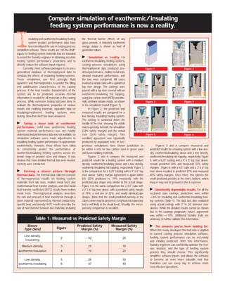
SlideShare a Scribd company logo
1 of 4
Download to read offline
V       O       L        U       M         E
                                                     1                  I       S       S       U       E
                                                                                                                  2


Large diameter KALMINEX* 35 RND sleeves
offer increased performance for heavy
section steel castings


R                ound neckdown (RND) sleeves
                  reduce riser contact area by 75% as
                 compared to full contact cylindrical
risers. This contact area reduction is the same as
can be obtained through the use of a 50% opening
breaker core on a full contact cylindrical riser. An
                                                          required to feed rangier castings is affected by the
                                                          performance of the riser sleeve, but to a lesser
                                                          degree than the volume of a riser required in a
                                                          modulus feed to a chunkier casting. KALMINEX 35
                                                          RND sleeves have a higher riser modulus than
                                                          KALMINEX 2000 RND sleeves and are more capable
RND sleeve has the additional advantages of being         of enhancing casting yield for heavy section
able to be located on a smaller casting contact           applications when compared to KALMINEX 2000
area and may offer the ability to be knocked off,         RND sleeves.
versus burning or cutting, for many alloys. Use of              Compared to a tube sleeve, the geometry
an RND sleeve can often reduce or eliminate metal         of an RND sleeve is not as efficient in providing
padding otherwise needed to achieve an adequate           a required modulus in a given sleeve volume to
riser contact to the casting.                             feed a casting. This is the trade-off to employ the
      KALMINEX* 2000 RND sleeves are available            contact advantage of an RND sleeve. Typically,
in diameters ranging from 2.5" to 12". KALMINEX 35        RND sleeve volume will have to be greater as
RND sleeves are now available in diameters ranging        compared to a cylindrical sleeve volume to provide
from 6" to 14" for increased riser performance in         an equivalent modulus for a given sleeve formulation.
larger sizes.                                             Using KALMINEX 35 RND sleeves versus
      When foundry handling is rigorous and               KALMINEX 2000 RND sleeves will increase the                  The increased performance possible with
the molding operation is demanding, the higher            yield when feeding heavy section castings.              KALMINEX 35 sleeves also provides a tool to
strength KALMINEX 35 formulation is required.             KALMINEX 35 RND sleeves increasingly outperform         the foundryman to minimize segregation that
Otherwise, to determine which product is right            KALMINEX 2000 RND sleeves with increasing               leads to under-riser cracking for segregation-prone
for a given application in the larger diameter            diameter. Additionally, KALMINEX 35 RND sleeves         alloys. Due to its increased thermal performance
sizes, one must consider a particular casting’s           have a higher sleeve density and are more resistant     in larger sizes, the KALMINEX 35 material is
geometry and its alloy’s feeding and solidification       to dilation from higher metallostatic head pressure     capable of providing a flatter feed that shows less
characteristics.                                          and longer freeze times.                                piping and is able to more readily produce a
      In general, for carbon steel castings, a riser            Limitations on feeding performance of             greater margin of good metal at the riser contact
starts with a minimum of 20% greater freezing             KALMINEX 2000 RND sleeves is not a great                as compared to KALMINEX 2000 material in a high
time and is adequate if it can remain liquid slightly     issue in final feed performance when a riser is         modulus feed. Normal process variables in hot
longer than the casting feeding from it. Geometry         chiefly sized to provide a given volume of feed         topping, pour height, pour temperature, metal
is useful in predicting whether casting feeders will      metal as required for average to rangy to               chemistry, and gas content can often produce
be tasked with a mainly modulus (freezing time) or        very rangy geometry castings. For chunky to             casting defects. KALMINEX 35 RND sleeves can
volume (feed metal) performance requirement.              very chunky geometry castings where modulus             give greater margin at a lower cost than
Very chunky castings with principal dimension             requirements are the primary driving selectors          KALMINEX 2000 RND sleeves when feed safety
ratios of 1 : 1.33 : 2 and chunky castings (1 : 2 : 4)    to sleeve size, an RND design having a greater          margin must be maintained.
generally place a heavy modulus feeding demand on         modulus feeding capacity is desirable. KALMINEX
a riser. For average (1 : 3 : 9) to rangy (1 : 10 : 10)   35 RND sleeves can achieve adequate feed with a
to very rangy (1 : 15 : 30) castings, riser               more economical casting yield than KALMINEX
performance is more a matter of providing an              2000 RND sleeves in diameters 6" and above.
adequate volume of feed metal. Initially, the             The KALMINEX 2000 formulation is still an eco-
freezing time of a riser for average to very rangy        nomical choice for volume feeding of castings
castings is much greater than that of the                 in larger sleeve sizes, especially for high feed
casting fed, until the casting begins freezing and        volume demand alloys having 8% or more feed
draining riser feed metal. The riser volume               metal demand.
The relationship between sleeves and hot topping


M              ost steel foundries have realized the value
               of using quality riser sleeves to reduce
               costs, either through increased casting
yield or through improved safety factors that reduce
scrap. However, by neglecting good hot topping
practice, many foundries only go part way to realizing
                                                             Mathematically, the modulus of a cylindrical feeder
                                                             with a sleeve and hot topping can be calculated as
                                                             shown in formula (1). The “ASAF” value stands for
                                                             Apparent Surface Alteration Factor and is empirically
                                                             derived. The ASAF value for silica sand is defined to be
                                                             1.0 and the values below that are a measure of the
                                                                                                                                                                        11"

                                                                                                                                                                        10"
                                                                                                                                                                                  30


                                                                                                                                                                                  25

all the benefits an efficient risering system can            relative feeding efficiency of a sleeve and topping.                                                       9"
provide. Good hot topping practice begins with a high                                                                                                                   8"
efficiency hot topping, applied at the right time in the      1
                                                             (1)    Mriser = =
                                                                    M riser           Height*Diameter
                                                                                                                                                                                  20

                                                                                   Height*Diameter
                                                                          (4*Height*ASAFsleeve) + (Diameter*ASAFtopping)                                                7"
right amount.
      The right amount is dependent on the size of the             (4*Height*ASAFsleeve) + (Diameter*ASAFtopping)                                                       6"        15

feeder since the topping added must produce a layer                                                                                                                     5"
equal to one-tenth of the feeder diameter. When              For the cube shown in Figure 2 with a sleeve ASAF                                                          4"        10
calculating the amount required for a hot topping            value of 0.75 and the ASAF of the sand topping at 1.0:
                                                                                                                                                                        3"
compound such as FERRUX* 746 topping, the
expansion of the topping also has to be taken into           (2)
                                                              2                                                                                                         2"        5
                                                                                       16.7*16.7
account. To minimize radiant heat loss, the topping                                                                                                                     1"
                                                                            (4*16.7*.75) + (16.7*1)                                                                Inch           Cm
should be applied as soon as the feeders are full.
      Figure 1 shows what happens when a casting                                                                           Figure 2. Silica Sand used as hot topping
                                                                                   =     4.18 cm
with a sleeve is poured without any topping at all.
Most of the heat is lost as radiant heat out the top
                                                             The high efficiency topping used on the cube in Figure
of the riser. While the top of a 250 mm diameter by
                                                             4 has an ASAF of 0.7. The new modulus calculation
200 mm high (10 x 8 inch) feeder only represents
                                                             is:
approximately 24% of the cooling surface area,                                                                                                                                30

it accounts for about 60% of the heat loss. The                                                                                                                        11"
solidification profile is very narrow, with shrinkage
                                                              3
                                                             (3)
                                                                                       16.7*16.7                                                                       10"    25
going into the casting.                                                     (4*16.7*.75) + (16.7*.7)                                                                   9"
      Radiation heat loss is kept to a minimum
                                                                                                                                                                       8"     20
(Figure 2) if dry silica sand is used as a topping, but                           =     4.51 cm
                                                                                                                                                                       7"
the shrinkage profile is only marginally improved.
Even though radiant heat loss is reduced, heat                                                                                                                         6"     15

transfer through the sand is still relatively high. The           This means that the solidification time has                                                          5"
resulting low safety margin is too close to the              increased from approximately 38 minutes to                                                                4"     10
casting. There may be enough alloy segregation at            almost 45 minutes just by adding a high efficiency
                                                                                                                                                                       3"
the contact to cause cracking problems during riser          hot topping.
                                                                                                                                                                       2"     5
removal or heat treatment.                                        In conclusion, a good sleeve is only part of
      A standard grade topping reduces the radiant           effective risering technique. A high efficiency hot                                                       1"
                                                                                                                                                                  Inch        Cm
heat loss and tries to reduce the heat loss due to           topping is also important to provide cost effective
convection. Used in conjunction with the sleeve              casting yield.                                                Figure 3. Standard Grade Topping
(Figure 3), it doubles the feed safety margin over
sand, but still may cause problems with segregation
in higher alloy steels.
      The best overall feeding system is shown in                                                                     30
Figure 4. The use of a sleeve with a high efficiency hot                                                        11"                                                          30

topping shows the best feed profile. The high                                                                                                                          11"
                                                                                                                10"   25
efficiency topping not only reduced the radiant heat                                                                                                                   10"   25
loss but it also kept the convection losses to a minimum.                                                       9"
                                                                                                                                                                       9"
Notice the “champagne glass” look to the feed profile:                                                          8"    20
                                                                                                                                                                       8"    20
most of the shrinkage is taken out of the top of the                                                            7"
feeder. The safety margin is five times greater when                                                                                                                   7"
                                                                                                                6"    15
using a high efficiency topping versus silica sand, and                                                                                                                6"    15
                                                                                                                5"
over twice that of a standard topping.                                                                                                                                 5"
      Why is this increase in safety margin important? A                                                        4"    10
                                                                                                                                                                       4"    10
certain safety margin is required (rule-of-thumb: 20%                                                           3"
                                                                                                                                                                       3"
for a top feeder) to make sure the casting is fed with-                                                         2"    5
out shrinkage and to keep alloy segregation to a min-                                                                                                                  2"    5
                                                                                                                1"
imum. To maintain this desired safety margin without                                                                                                                   1"
                                                                                                              Inch    Cm                                          Inch        Cm
the use of a high efficiency topping, these cubes
would need a larger feeder.                                    Figure 1. 20 cm cube with no topping                        Figure 4. High Efficiency Topping
Computer simulation of exothermic/insulating
                             feeding system performance is now a reality.


I          nsulating and exothermic/insulating feeding
           system product performance data have
           been developed for use in casting process
simulation software. These results are “off-the-shelf”
inputs for feeding system materials that are intended
                                                            the thermal barrier effects of any
                                                            gases present. A material’s exothermic
                                                            energy output is shown as heat of
                                                            generation values.

to assist the foundry engineer in obtaining accurate       ᮣ Simulation vs. reality. For
feeding system performance predictions and to              exothermic/insulating feeding systems,
directly reduce the software input required.               casting process simulations using
      Currently, most software packages try to use a       thermophysical data produced pre-                            Figure 1                             Figure 2
generalized database of thermophysical data to             dicted performance, molten metal tests
simulate the effects of insulating feeding systems.        showed measured performance, and
These simulations use first principle fluid                the two were compared. All cases
dynamics and thermodynamics to predict the filling         involved a simple cube with a cylindrical
and solidification characteristics of the casting          top riser design. The castings were
process. If the heat transfer characteristics of the       poured with a top riser covered with an
system are to be predicted, accurate thermal               exothermic/ insulating hot topping,
information is needed for all materials in the casting     using low carbon steel (WCB) and phe-
process. While extensive testing had been done to          nolic urethane nobake molds, as shown                        Figure 3                             Figure 4
evaluate the thermodynamic properties of various           in the simulation model (Figure 1).
metals and molding materials, equivalent data on                 In Figure 2, the predicted and
insulating/exothermic feeding systems were                 measured results are compared for a
lacking. Now that need has been answered.                  low density, insulating feeding system.
                                                           The casting is sectioned down the
ᮣ Taking a closer look at exothermic                       middle of the riser, showing the visible
performance. Until now, exothermic feeding                 macro-porosity for both the simulation
system material performance was not readily                (32% safety margin) and the actual
understood and performance data was not available, so      riser (26% safety margin). This                              Figure 5                             Figure 6
simulation software users made adjustments to              excellent agreement was repeatedly
insulating feeding system performance to approximate       produced by equivalent tests. In fact,
exothermicity. However, these efforts have failed          previous simulations have shown prediction to                          Figures 5 and 6 compare measured and
to consistently predict the performance of                 be within +/-6% for low carbon steel in green sand               predicted results for a feeding system with a low den-
exothermic/insulating feeding systems across the           and furan molding materials.                                     sity, exothermic/insulating sleeve and a low density,
broad range of product sizes and shapes. It was                  Figures 3 and 4 compare the measured and                   exothermic/insulating hot topping, respectively. Figure
obvious that more detailed thermal data were needed,       predicted results for a feeding system with a medium             5, with a 6.25" casting and a 4" x 5" top riser sleeve,
so tests were conducted.                                   density, exothermic/insulating sleeve and a low density,         reveals predicted 26% and measured 32% safety
                                                           exothermic/insulating hot topping, respectively. Figure 3        margins. Figure 6, with a 4.5" cube and a 3" x 6" top
ᮣ Forming a clearer picture through                        is the comparison for a 6.25" casting with a 4" x 6" top         riser sleeve resulted in predicted 37% and measured
thermal data. The thermal data collected consists          riser sleeve. Safety margin agreement is again within            40% safety margins. Once more, this ignores the
of thermophysical results on feeding system                6% (25% predicted vs. 19% measured), with the                    small predicted porosity at the riser’s bottom, which
materials from lab tests, molten metal tests and           predicted pipe shape very similar to the actual shape.           may or may not be present at the X-ray level.
mathematical heat transfer analysis, and inter-facial      Figure 4 is the same comparison for a 4.5" cube with
heat transfer coefficient (IHTC) results from molten       a 3" x 6" top riser sleeve, with a predicted safety margin       ᮣ Consistently dependable results. For all the
metal tests. Thermophysical analysis describes             of 19%, a real one of 22%, and nearly identical pipe             sectioned cube castings, predictions were within
the rate and amount of heat transferred through a          shapes. (Note that the small predicted porosity in the           +/-6% for insulating and exothermic/insulating feed-
given material represented by thermal conductivity,        cubes center may be present in X-ray level microporosity,        ing systems (Table 1). The data was also evaluated
specific heat, and density. IHTC results describe the      but is not likely at the visual level.) Visually, the micro-     using actual castings with 2" to 26" diameter riser
rate of heat transfer between two materials, including     porosity comparison is excellent.                                sleeves. While the detailed results cannot be shown
                                                                                                                            due to the castings’ proprietary nature, agreement
                                                                                                                            was within +/-10%. Additional foundry trials are
                Table 1: Measured vs                     Predicted Safety Margin                                            underway to further validate this information.

        Sleeve                                           Predicted Safety              Measured Safety                      ᮣ The answers you've been looking for.
      Type (Size)                   Figure                 Margin (%)                    Margin (%)                         When this newly developed thermal data is applied
                                                                                                                            to current casting process simulation software,
      Low density,
                                        2                         32                              26                        feeding system performance can be accurately
       insulating                                                                                                           and reliably predicted. With this information,
    Medium density,                     3                         25                              19                        foundry engineers can confidently optimize the riser
                                                                                                                            size, location, and the type of feeding system
 exothermic/insulation                  4                         19                              22                        product they should choose. This significantly
                                                                                                                            simplifies software inputs, and allows the software
     Low density,                       5                         26                              32                        to become an even more valuable tool that
 exothermic/insulating                  6                         37                              40                        foundries can use every day to achieve more
                                                                                                                            cost-effective operations.
Maintaining feed safety margins for uncovered riser sleeves.


D                    ue to cost factors, foundries often
                     do not fill their mold flasks with
                     sand all the way to the top, leaving
   1-2 inches of the feeder sleeve uncovered and
   exposed to ambient conditions. To assess the effects
   on feed safety margin performance, Foseco simulated
                                                             mold filling solidification simulation software program.
                                                             The result of these simulations indicated a definite
                                                             correlation between exposed height and loss of the
                                                             safety margin, represented by a simple curve as
                                                             shown in Figure 1.
                                                                  If 25% of the sleeve height is exposed, then
                                                                                                                                                                                   the problem. Most of the lost performance can be
                                                                                                                                                                                   regained by conically mounding sand around the top
                                                                                                                                                                                   of the riser sleeve to a thickness of 15% of the riser
                                                                                                                                                                                   diameter. Nearly all of the performance can be
                                                                                                                                                                                   regained if the mounded sand ring thickness is 25%
                                                                                                                                                                                   of the riser diameter. This approach can also be
   this practice using MAGMASOFT™, a first-principles        approximately 9% of the feed performance may be                                                                       applied to exothermic riser sleeves with similar
                                                                                           lost. For instance, for a                                                               beneficial results, giving foundries an easy and
                                                                                           6" x 6" KALMIN* 70 riser                                                                inexpensive way to reach their performance goals.
                                                                                           sleeve on a 6.25" cube with
            0
                        5       10        15       20       25         30         35       the top 1.5" of the riser
                                                                                           sleeve exposed (25%), the
           -2                                                                              safety margin performance
                                                                                           is reduced from 39% to
       Reduction in SM (%)


           -4                                                                              30%. If more than 1/3
                                                                                           (33%) of the sleeve is
           -6                                                                              exposed, feed performance
                                                                                           becomes severely affected,
                                                                                           and feed performance
           -8
                                                                                           cannot be guaranteed.
                                                                                                However, it is not
          -10                                                                              necessary to increase the
                                                                                           overall height of the mold to
          -12                                                                              counteract these negative
                                Sleeve Height Unmolded (%)                                 effects. Simply forming
                                                                                           a ring of sand around
      Figure 1. Effect of unmolded riser sleeve height on feed safety
                                                                                           the exposed riser sleeve
      performance
                                                                                           section can help to solve


                                        Feeding Systems Facts are intended to promote the exchange of information,
                                   to contribute to the fund of available knowledge in the foundry industry and to promote
                                        good feeding system practice. Foseco will also use Feeding System Facts to
                                     highlight new products and concepts and to provide application tips and guidance.

All rights reserved. No part of this publication may be reproduced, stored in a retrieval system of any nature or transmitted in any form or by any means, including photocopying and recording, without the written permission of the copyright holder.
All statements, information and data contained herein are published as a guide and although believed to be accurate and reliable (having regard to the manufacturer’s practical experience), neither the manufacturer, licensor, seller nor publisher
represents or warrants, expressly or implied: (1) their accuracy / reliability (2) that the use of the product(s) will not infringe third party rights (3) that no further safety measures are requested to meet local legislation. The seller is not authorized to
make representations nor contract on behalf of the manufacturer/seller. All sales by the manufacturer/seller are based on their respective conditions of sale, available on request.
*FERRUX, KALMINEX and KALMIN are Trade Marks of the Foseco Group of Companies.
™
  MAGMASOFT is a trademark of Magma, GmbH.


                                             A NEW PERSPECTIVE ON PERFORMANCE

                                                          Foseco Metallurgical Inc 20200 Sheldon Rd Cleveland OH 44142, 440-826-4548 © Foseco Metallurgical Inc 2004Foseco, Inc. ● Printed inStheldon
                                                                                                                                                                                    20200 he U.S.A

More Related Content

What's hot

TALAT Lecture 3206: The Feeding of Castings
TALAT Lecture 3206: The Feeding of CastingsTALAT Lecture 3206: The Feeding of Castings
TALAT Lecture 3206: The Feeding of CastingsCORE-Materials
 
03 aleaciones metalicas
03   aleaciones metalicas03   aleaciones metalicas
03 aleaciones metalicasSegundo EspĂ­n
 
Ch 27.4 plain carbon steel
Ch 27.4 plain carbon steelCh 27.4 plain carbon steel
Ch 27.4 plain carbon steelNandan Choudhary
 
plasma nitriding
plasma nitridingplasma nitriding
plasma nitridingansion005
 
Ceramic matrix composite
Ceramic matrix compositeCeramic matrix composite
Ceramic matrix compositeGulfam Hussain
 
Refractory in steel ladle application
Refractory in steel ladle applicationRefractory in steel ladle application
Refractory in steel ladle applicationsat9583
 
Introduction to modern concept of steel making through induction furnaces by ...
Introduction to modern concept of steel making through induction furnaces by ...Introduction to modern concept of steel making through induction furnaces by ...
Introduction to modern concept of steel making through induction furnaces by ...steadfast123
 
weldability study of nickel super alloys
weldability study of nickel super alloysweldability study of nickel super alloys
weldability study of nickel super alloysArchunan Ponnukhan
 
CERAMICS AND COMPOSITE MATERIALS
CERAMICS AND COMPOSITE MATERIALSCERAMICS AND COMPOSITE MATERIALS
CERAMICS AND COMPOSITE MATERIALSChandra Kumar S
 
Surface Hardening of Steel
Surface Hardening of SteelSurface Hardening of Steel
Surface Hardening of Steelvaibhav tailor
 
04 copper and copper alloys
04 copper and copper alloys04 copper and copper alloys
04 copper and copper alloysJayanth Abdullah
 
Thermochemical Processes
Thermochemical ProcessesThermochemical Processes
Thermochemical ProcessesSaiGayathri12
 
classification of refractories and commonly used refractory bricks
classification of refractories and commonly used refractory bricksclassification of refractories and commonly used refractory bricks
classification of refractories and commonly used refractory brickssunrise refractory
 
Materiales II- Tratamientos térmicos-Semana 11
Materiales II-  Tratamientos térmicos-Semana 11Materiales II-  Tratamientos térmicos-Semana 11
Materiales II- Tratamientos térmicos-Semana 11Jorge Martinez
 

What's hot (20)

TALAT Lecture 3206: The Feeding of Castings
TALAT Lecture 3206: The Feeding of CastingsTALAT Lecture 3206: The Feeding of Castings
TALAT Lecture 3206: The Feeding of Castings
 
03 aleaciones metalicas
03   aleaciones metalicas03   aleaciones metalicas
03 aleaciones metalicas
 
Ch 27.4 plain carbon steel
Ch 27.4 plain carbon steelCh 27.4 plain carbon steel
Ch 27.4 plain carbon steel
 
plasma nitriding
plasma nitridingplasma nitriding
plasma nitriding
 
Ceramic matrix composite
Ceramic matrix compositeCeramic matrix composite
Ceramic matrix composite
 
Presentación 2 - Estructuras cristalinas cerámicos, tipos de enlace.
Presentación 2 - Estructuras cristalinas cerámicos, tipos de enlace.Presentación 2 - Estructuras cristalinas cerámicos, tipos de enlace.
Presentación 2 - Estructuras cristalinas cerámicos, tipos de enlace.
 
Steel Making: Lecture open hearth furnace
Steel Making: Lecture open hearth furnaceSteel Making: Lecture open hearth furnace
Steel Making: Lecture open hearth furnace
 
Refractory in steel ladle application
Refractory in steel ladle applicationRefractory in steel ladle application
Refractory in steel ladle application
 
precipitation hardening
precipitation hardeningprecipitation hardening
precipitation hardening
 
Introduction to modern concept of steel making through induction furnaces by ...
Introduction to modern concept of steel making through induction furnaces by ...Introduction to modern concept of steel making through induction furnaces by ...
Introduction to modern concept of steel making through induction furnaces by ...
 
weldability study of nickel super alloys
weldability study of nickel super alloysweldability study of nickel super alloys
weldability study of nickel super alloys
 
Phase diagrams
Phase diagramsPhase diagrams
Phase diagrams
 
CERAMICS AND COMPOSITE MATERIALS
CERAMICS AND COMPOSITE MATERIALSCERAMICS AND COMPOSITE MATERIALS
CERAMICS AND COMPOSITE MATERIALS
 
Surface Hardening of Steel
Surface Hardening of SteelSurface Hardening of Steel
Surface Hardening of Steel
 
04 copper and copper alloys
04 copper and copper alloys04 copper and copper alloys
04 copper and copper alloys
 
Thermochemical Processes
Thermochemical ProcessesThermochemical Processes
Thermochemical Processes
 
classification of refractories and commonly used refractory bricks
classification of refractories and commonly used refractory bricksclassification of refractories and commonly used refractory bricks
classification of refractories and commonly used refractory bricks
 
Steel MAking: Lecture Vacuum Degassing, VOD, Ladle-De-S, ESR
Steel MAking: Lecture Vacuum Degassing, VOD, Ladle-De-S, ESRSteel MAking: Lecture Vacuum Degassing, VOD, Ladle-De-S, ESR
Steel MAking: Lecture Vacuum Degassing, VOD, Ladle-De-S, ESR
 
Materiales II- Tratamientos térmicos-Semana 11
Materiales II-  Tratamientos térmicos-Semana 11Materiales II-  Tratamientos térmicos-Semana 11
Materiales II- Tratamientos térmicos-Semana 11
 
Arrabio
ArrabioArrabio
Arrabio
 

Similar to Index foseco

clutch friction material.pdf
clutch friction material.pdfclutch friction material.pdf
clutch friction material.pdfFactsScoop
 
SPIROL Compression Limiters Design Guide
SPIROL Compression Limiters Design GuideSPIROL Compression Limiters Design Guide
SPIROL Compression Limiters Design GuideSPIROL
 
6 High Reversible Cold Rolling Mill
6 High Reversible Cold Rolling Mill6 High Reversible Cold Rolling Mill
6 High Reversible Cold Rolling MillSteel Cosmos
 
Foundry Guide to using TiBor Aluminum Grain Refiner and Modification with Str...
Foundry Guide to using TiBor Aluminum Grain Refiner and Modification with Str...Foundry Guide to using TiBor Aluminum Grain Refiner and Modification with Str...
Foundry Guide to using TiBor Aluminum Grain Refiner and Modification with Str...Hobby Foundry
 
Cosmos Pumps - Submersible Dewatering Pumps.pdf
Cosmos Pumps - Submersible Dewatering Pumps.pdfCosmos Pumps - Submersible Dewatering Pumps.pdf
Cosmos Pumps - Submersible Dewatering Pumps.pdfCosmos Pumps
 
Cmd brochure
Cmd brochureCmd brochure
Cmd brochureEko Kiswanto
 
Roll Pass Design strategy
Roll Pass Design strategyRoll Pass Design strategy
Roll Pass Design strategySead Spuzic
 
Monitoring Coal mill Performance
Monitoring Coal mill PerformanceMonitoring Coal mill Performance
Monitoring Coal mill PerformanceManohar Tatwawadi
 
BM-Maintenance-Damia Cement.ppt
BM-Maintenance-Damia Cement.pptBM-Maintenance-Damia Cement.ppt
BM-Maintenance-Damia Cement.pptDinesh566323
 
Industrial type gas turbine combustion chamber
Industrial type gas turbine combustion chamberIndustrial type gas turbine combustion chamber
Industrial type gas turbine combustion chamberHemanth Krishnan R
 
Improved Material and Enhanced Fatigue Resistance for Gear Components
Improved Material and Enhanced Fatigue Resistance for Gear ComponentsImproved Material and Enhanced Fatigue Resistance for Gear Components
Improved Material and Enhanced Fatigue Resistance for Gear ComponentsALD Vacuum Systems Inc.
 
Presentation
PresentationPresentation
PresentationSethu Ram
 
Information of injection molding screw
Information of injection molding screwInformation of injection molding screw
Information of injection molding screwNaik Devang
 

Similar to Index foseco (20)

Trafo seco
Trafo secoTrafo seco
Trafo seco
 
3 ENGINE CONSTRUCTION1.pptx
3 ENGINE CONSTRUCTION1.pptx3 ENGINE CONSTRUCTION1.pptx
3 ENGINE CONSTRUCTION1.pptx
 
clutch friction material.pdf
clutch friction material.pdfclutch friction material.pdf
clutch friction material.pdf
 
Greyhound Chromatography 'Q Cap' Capillary Columns
Greyhound Chromatography 'Q Cap' Capillary ColumnsGreyhound Chromatography 'Q Cap' Capillary Columns
Greyhound Chromatography 'Q Cap' Capillary Columns
 
421110
421110421110
421110
 
SPIROL Compression Limiters Design Guide
SPIROL Compression Limiters Design GuideSPIROL Compression Limiters Design Guide
SPIROL Compression Limiters Design Guide
 
6 High Reversible Cold Rolling Mill
6 High Reversible Cold Rolling Mill6 High Reversible Cold Rolling Mill
6 High Reversible Cold Rolling Mill
 
Foundry Guide to using TiBor Aluminum Grain Refiner and Modification with Str...
Foundry Guide to using TiBor Aluminum Grain Refiner and Modification with Str...Foundry Guide to using TiBor Aluminum Grain Refiner and Modification with Str...
Foundry Guide to using TiBor Aluminum Grain Refiner and Modification with Str...
 
Cosmos Pumps - Submersible Dewatering Pumps.pdf
Cosmos Pumps - Submersible Dewatering Pumps.pdfCosmos Pumps - Submersible Dewatering Pumps.pdf
Cosmos Pumps - Submersible Dewatering Pumps.pdf
 
Cmd brochure
Cmd brochureCmd brochure
Cmd brochure
 
Pipe body properties catalogue
Pipe body properties catalogue Pipe body properties catalogue
Pipe body properties catalogue
 
Roll Pass Design strategy
Roll Pass Design strategyRoll Pass Design strategy
Roll Pass Design strategy
 
Monitoring Coal mill Performance
Monitoring Coal mill PerformanceMonitoring Coal mill Performance
Monitoring Coal mill Performance
 
BM-Maintenance-Damia Cement.ppt
BM-Maintenance-Damia Cement.pptBM-Maintenance-Damia Cement.ppt
BM-Maintenance-Damia Cement.ppt
 
Industrial type gas turbine combustion chamber
Industrial type gas turbine combustion chamberIndustrial type gas turbine combustion chamber
Industrial type gas turbine combustion chamber
 
Improved Material and Enhanced Fatigue Resistance for Gear Components
Improved Material and Enhanced Fatigue Resistance for Gear ComponentsImproved Material and Enhanced Fatigue Resistance for Gear Components
Improved Material and Enhanced Fatigue Resistance for Gear Components
 
Soft armor
Soft armorSoft armor
Soft armor
 
Soft armor
Soft armorSoft armor
Soft armor
 
Presentation
PresentationPresentation
Presentation
 
Information of injection molding screw
Information of injection molding screwInformation of injection molding screw
Information of injection molding screw
 

Recently uploaded

AI as an Interface for Commercial Buildings
AI as an Interface for Commercial BuildingsAI as an Interface for Commercial Buildings
AI as an Interface for Commercial BuildingsMemoori
 
Understanding the Laravel MVC Architecture
Understanding the Laravel MVC ArchitectureUnderstanding the Laravel MVC Architecture
Understanding the Laravel MVC ArchitecturePixlogix Infotech
 
Benefits Of Flutter Compared To Other Frameworks
Benefits Of Flutter Compared To Other FrameworksBenefits Of Flutter Compared To Other Frameworks
Benefits Of Flutter Compared To Other FrameworksSoftradix Technologies
 
"Debugging python applications inside k8s environment", Andrii Soldatenko
"Debugging python applications inside k8s environment", Andrii Soldatenko"Debugging python applications inside k8s environment", Andrii Soldatenko
"Debugging python applications inside k8s environment", Andrii SoldatenkoFwdays
 
CloudStudio User manual (basic edition):
CloudStudio User manual (basic edition):CloudStudio User manual (basic edition):
CloudStudio User manual (basic edition):comworks
 
Pigging Solutions in Pet Food Manufacturing
Pigging Solutions in Pet Food ManufacturingPigging Solutions in Pet Food Manufacturing
Pigging Solutions in Pet Food ManufacturingPigging Solutions
 
Beyond Boundaries: Leveraging No-Code Solutions for Industry Innovation
Beyond Boundaries: Leveraging No-Code Solutions for Industry InnovationBeyond Boundaries: Leveraging No-Code Solutions for Industry Innovation
Beyond Boundaries: Leveraging No-Code Solutions for Industry InnovationSafe Software
 
SIP trunking in Janus @ Kamailio World 2024
SIP trunking in Janus @ Kamailio World 2024SIP trunking in Janus @ Kamailio World 2024
SIP trunking in Janus @ Kamailio World 2024Lorenzo Miniero
 
Tampa BSides - Chef's Tour of Microsoft Security Adoption Framework (SAF)
Tampa BSides - Chef's Tour of Microsoft Security Adoption Framework (SAF)Tampa BSides - Chef's Tour of Microsoft Security Adoption Framework (SAF)
Tampa BSides - Chef's Tour of Microsoft Security Adoption Framework (SAF)Mark Simos
 
Kotlin Multiplatform & Compose Multiplatform - Starter kit for pragmatics
Kotlin Multiplatform & Compose Multiplatform - Starter kit for pragmaticsKotlin Multiplatform & Compose Multiplatform - Starter kit for pragmatics
Kotlin Multiplatform & Compose Multiplatform - Starter kit for pragmaticscarlostorres15106
 
My INSURER PTE LTD - Insurtech Innovation Award 2024
My INSURER PTE LTD - Insurtech Innovation Award 2024My INSURER PTE LTD - Insurtech Innovation Award 2024
My INSURER PTE LTD - Insurtech Innovation Award 2024The Digital Insurer
 
New from BookNet Canada for 2024: BNC BiblioShare - Tech Forum 2024
New from BookNet Canada for 2024: BNC BiblioShare - Tech Forum 2024New from BookNet Canada for 2024: BNC BiblioShare - Tech Forum 2024
New from BookNet Canada for 2024: BNC BiblioShare - Tech Forum 2024BookNet Canada
 
Bluetooth Controlled Car with Arduino.pdf
Bluetooth Controlled Car with Arduino.pdfBluetooth Controlled Car with Arduino.pdf
Bluetooth Controlled Car with Arduino.pdfngoud9212
 
Streamlining Python Development: A Guide to a Modern Project Setup
Streamlining Python Development: A Guide to a Modern Project SetupStreamlining Python Development: A Guide to a Modern Project Setup
Streamlining Python Development: A Guide to a Modern Project SetupFlorian Wilhelm
 
Unraveling Multimodality with Large Language Models.pdf
Unraveling Multimodality with Large Language Models.pdfUnraveling Multimodality with Large Language Models.pdf
Unraveling Multimodality with Large Language Models.pdfAlex Barbosa Coqueiro
 
Vertex AI Gemini Prompt Engineering Tips
Vertex AI Gemini Prompt Engineering TipsVertex AI Gemini Prompt Engineering Tips
Vertex AI Gemini Prompt Engineering TipsMiki Katsuragi
 
Automating Business Process via MuleSoft Composer | Bangalore MuleSoft Meetup...
Automating Business Process via MuleSoft Composer | Bangalore MuleSoft Meetup...Automating Business Process via MuleSoft Composer | Bangalore MuleSoft Meetup...
Automating Business Process via MuleSoft Composer | Bangalore MuleSoft Meetup...shyamraj55
 
My Hashitalk Indonesia April 2024 Presentation
My Hashitalk Indonesia April 2024 PresentationMy Hashitalk Indonesia April 2024 Presentation
My Hashitalk Indonesia April 2024 PresentationRidwan Fadjar
 

Recently uploaded (20)

AI as an Interface for Commercial Buildings
AI as an Interface for Commercial BuildingsAI as an Interface for Commercial Buildings
AI as an Interface for Commercial Buildings
 
Understanding the Laravel MVC Architecture
Understanding the Laravel MVC ArchitectureUnderstanding the Laravel MVC Architecture
Understanding the Laravel MVC Architecture
 
Benefits Of Flutter Compared To Other Frameworks
Benefits Of Flutter Compared To Other FrameworksBenefits Of Flutter Compared To Other Frameworks
Benefits Of Flutter Compared To Other Frameworks
 
"Debugging python applications inside k8s environment", Andrii Soldatenko
"Debugging python applications inside k8s environment", Andrii Soldatenko"Debugging python applications inside k8s environment", Andrii Soldatenko
"Debugging python applications inside k8s environment", Andrii Soldatenko
 
CloudStudio User manual (basic edition):
CloudStudio User manual (basic edition):CloudStudio User manual (basic edition):
CloudStudio User manual (basic edition):
 
Pigging Solutions in Pet Food Manufacturing
Pigging Solutions in Pet Food ManufacturingPigging Solutions in Pet Food Manufacturing
Pigging Solutions in Pet Food Manufacturing
 
Beyond Boundaries: Leveraging No-Code Solutions for Industry Innovation
Beyond Boundaries: Leveraging No-Code Solutions for Industry InnovationBeyond Boundaries: Leveraging No-Code Solutions for Industry Innovation
Beyond Boundaries: Leveraging No-Code Solutions for Industry Innovation
 
SIP trunking in Janus @ Kamailio World 2024
SIP trunking in Janus @ Kamailio World 2024SIP trunking in Janus @ Kamailio World 2024
SIP trunking in Janus @ Kamailio World 2024
 
Tampa BSides - Chef's Tour of Microsoft Security Adoption Framework (SAF)
Tampa BSides - Chef's Tour of Microsoft Security Adoption Framework (SAF)Tampa BSides - Chef's Tour of Microsoft Security Adoption Framework (SAF)
Tampa BSides - Chef's Tour of Microsoft Security Adoption Framework (SAF)
 
Kotlin Multiplatform & Compose Multiplatform - Starter kit for pragmatics
Kotlin Multiplatform & Compose Multiplatform - Starter kit for pragmaticsKotlin Multiplatform & Compose Multiplatform - Starter kit for pragmatics
Kotlin Multiplatform & Compose Multiplatform - Starter kit for pragmatics
 
Hot Sexy call girls in Panjabi Bagh 🔝 9953056974 🔝 Delhi escort Service
Hot Sexy call girls in Panjabi Bagh 🔝 9953056974 🔝 Delhi escort ServiceHot Sexy call girls in Panjabi Bagh 🔝 9953056974 🔝 Delhi escort Service
Hot Sexy call girls in Panjabi Bagh 🔝 9953056974 🔝 Delhi escort Service
 
My INSURER PTE LTD - Insurtech Innovation Award 2024
My INSURER PTE LTD - Insurtech Innovation Award 2024My INSURER PTE LTD - Insurtech Innovation Award 2024
My INSURER PTE LTD - Insurtech Innovation Award 2024
 
New from BookNet Canada for 2024: BNC BiblioShare - Tech Forum 2024
New from BookNet Canada for 2024: BNC BiblioShare - Tech Forum 2024New from BookNet Canada for 2024: BNC BiblioShare - Tech Forum 2024
New from BookNet Canada for 2024: BNC BiblioShare - Tech Forum 2024
 
Bluetooth Controlled Car with Arduino.pdf
Bluetooth Controlled Car with Arduino.pdfBluetooth Controlled Car with Arduino.pdf
Bluetooth Controlled Car with Arduino.pdf
 
Streamlining Python Development: A Guide to a Modern Project Setup
Streamlining Python Development: A Guide to a Modern Project SetupStreamlining Python Development: A Guide to a Modern Project Setup
Streamlining Python Development: A Guide to a Modern Project Setup
 
Unraveling Multimodality with Large Language Models.pdf
Unraveling Multimodality with Large Language Models.pdfUnraveling Multimodality with Large Language Models.pdf
Unraveling Multimodality with Large Language Models.pdf
 
Vertex AI Gemini Prompt Engineering Tips
Vertex AI Gemini Prompt Engineering TipsVertex AI Gemini Prompt Engineering Tips
Vertex AI Gemini Prompt Engineering Tips
 
Automating Business Process via MuleSoft Composer | Bangalore MuleSoft Meetup...
Automating Business Process via MuleSoft Composer | Bangalore MuleSoft Meetup...Automating Business Process via MuleSoft Composer | Bangalore MuleSoft Meetup...
Automating Business Process via MuleSoft Composer | Bangalore MuleSoft Meetup...
 
E-Vehicle_Hacking_by_Parul Sharma_null_owasp.pptx
E-Vehicle_Hacking_by_Parul Sharma_null_owasp.pptxE-Vehicle_Hacking_by_Parul Sharma_null_owasp.pptx
E-Vehicle_Hacking_by_Parul Sharma_null_owasp.pptx
 
My Hashitalk Indonesia April 2024 Presentation
My Hashitalk Indonesia April 2024 PresentationMy Hashitalk Indonesia April 2024 Presentation
My Hashitalk Indonesia April 2024 Presentation
 

Index foseco

  • 1. V O L U M E 1 I S S U E 2 Large diameter KALMINEX* 35 RND sleeves offer increased performance for heavy section steel castings R ound neckdown (RND) sleeves reduce riser contact area by 75% as compared to full contact cylindrical risers. This contact area reduction is the same as can be obtained through the use of a 50% opening breaker core on a full contact cylindrical riser. An required to feed rangier castings is affected by the performance of the riser sleeve, but to a lesser degree than the volume of a riser required in a modulus feed to a chunkier casting. KALMINEX 35 RND sleeves have a higher riser modulus than KALMINEX 2000 RND sleeves and are more capable RND sleeve has the additional advantages of being of enhancing casting yield for heavy section able to be located on a smaller casting contact applications when compared to KALMINEX 2000 area and may offer the ability to be knocked off, RND sleeves. versus burning or cutting, for many alloys. Use of Compared to a tube sleeve, the geometry an RND sleeve can often reduce or eliminate metal of an RND sleeve is not as efficient in providing padding otherwise needed to achieve an adequate a required modulus in a given sleeve volume to riser contact to the casting. feed a casting. This is the trade-off to employ the KALMINEX* 2000 RND sleeves are available contact advantage of an RND sleeve. Typically, in diameters ranging from 2.5" to 12". KALMINEX 35 RND sleeve volume will have to be greater as RND sleeves are now available in diameters ranging compared to a cylindrical sleeve volume to provide from 6" to 14" for increased riser performance in an equivalent modulus for a given sleeve formulation. larger sizes. Using KALMINEX 35 RND sleeves versus When foundry handling is rigorous and KALMINEX 2000 RND sleeves will increase the The increased performance possible with the molding operation is demanding, the higher yield when feeding heavy section castings. KALMINEX 35 sleeves also provides a tool to strength KALMINEX 35 formulation is required. KALMINEX 35 RND sleeves increasingly outperform the foundryman to minimize segregation that Otherwise, to determine which product is right KALMINEX 2000 RND sleeves with increasing leads to under-riser cracking for segregation-prone for a given application in the larger diameter diameter. Additionally, KALMINEX 35 RND sleeves alloys. Due to its increased thermal performance sizes, one must consider a particular casting’s have a higher sleeve density and are more resistant in larger sizes, the KALMINEX 35 material is geometry and its alloy’s feeding and solidification to dilation from higher metallostatic head pressure capable of providing a flatter feed that shows less characteristics. and longer freeze times. piping and is able to more readily produce a In general, for carbon steel castings, a riser Limitations on feeding performance of greater margin of good metal at the riser contact starts with a minimum of 20% greater freezing KALMINEX 2000 RND sleeves is not a great as compared to KALMINEX 2000 material in a high time and is adequate if it can remain liquid slightly issue in final feed performance when a riser is modulus feed. Normal process variables in hot longer than the casting feeding from it. Geometry chiefly sized to provide a given volume of feed topping, pour height, pour temperature, metal is useful in predicting whether casting feeders will metal as required for average to rangy to chemistry, and gas content can often produce be tasked with a mainly modulus (freezing time) or very rangy geometry castings. For chunky to casting defects. KALMINEX 35 RND sleeves can volume (feed metal) performance requirement. very chunky geometry castings where modulus give greater margin at a lower cost than Very chunky castings with principal dimension requirements are the primary driving selectors KALMINEX 2000 RND sleeves when feed safety ratios of 1 : 1.33 : 2 and chunky castings (1 : 2 : 4) to sleeve size, an RND design having a greater margin must be maintained. generally place a heavy modulus feeding demand on modulus feeding capacity is desirable. KALMINEX a riser. For average (1 : 3 : 9) to rangy (1 : 10 : 10) 35 RND sleeves can achieve adequate feed with a to very rangy (1 : 15 : 30) castings, riser more economical casting yield than KALMINEX performance is more a matter of providing an 2000 RND sleeves in diameters 6" and above. adequate volume of feed metal. Initially, the The KALMINEX 2000 formulation is still an eco- freezing time of a riser for average to very rangy nomical choice for volume feeding of castings castings is much greater than that of the in larger sleeve sizes, especially for high feed casting fed, until the casting begins freezing and volume demand alloys having 8% or more feed draining riser feed metal. The riser volume metal demand.
  • 2. The relationship between sleeves and hot topping M ost steel foundries have realized the value of using quality riser sleeves to reduce costs, either through increased casting yield or through improved safety factors that reduce scrap. However, by neglecting good hot topping practice, many foundries only go part way to realizing Mathematically, the modulus of a cylindrical feeder with a sleeve and hot topping can be calculated as shown in formula (1). The “ASAF” value stands for Apparent Surface Alteration Factor and is empirically derived. The ASAF value for silica sand is defined to be 1.0 and the values below that are a measure of the 11" 10" 30 25 all the benefits an efficient risering system can relative feeding efficiency of a sleeve and topping. 9" provide. Good hot topping practice begins with a high 8" efficiency hot topping, applied at the right time in the 1 (1) Mriser = = M riser Height*Diameter 20 Height*Diameter (4*Height*ASAFsleeve) + (Diameter*ASAFtopping) 7" right amount. The right amount is dependent on the size of the (4*Height*ASAFsleeve) + (Diameter*ASAFtopping) 6" 15 feeder since the topping added must produce a layer 5" equal to one-tenth of the feeder diameter. When For the cube shown in Figure 2 with a sleeve ASAF 4" 10 calculating the amount required for a hot topping value of 0.75 and the ASAF of the sand topping at 1.0: 3" compound such as FERRUX* 746 topping, the expansion of the topping also has to be taken into (2) 2 2" 5 16.7*16.7 account. To minimize radiant heat loss, the topping 1" (4*16.7*.75) + (16.7*1) Inch Cm should be applied as soon as the feeders are full. Figure 1 shows what happens when a casting Figure 2. Silica Sand used as hot topping = 4.18 cm with a sleeve is poured without any topping at all. Most of the heat is lost as radiant heat out the top The high efficiency topping used on the cube in Figure of the riser. While the top of a 250 mm diameter by 4 has an ASAF of 0.7. The new modulus calculation 200 mm high (10 x 8 inch) feeder only represents is: approximately 24% of the cooling surface area, 30 it accounts for about 60% of the heat loss. The 11" solidification profile is very narrow, with shrinkage 3 (3) 16.7*16.7 10" 25 going into the casting. (4*16.7*.75) + (16.7*.7) 9" Radiation heat loss is kept to a minimum 8" 20 (Figure 2) if dry silica sand is used as a topping, but = 4.51 cm 7" the shrinkage profile is only marginally improved. Even though radiant heat loss is reduced, heat 6" 15 transfer through the sand is still relatively high. The This means that the solidification time has 5" resulting low safety margin is too close to the increased from approximately 38 minutes to 4" 10 casting. There may be enough alloy segregation at almost 45 minutes just by adding a high efficiency 3" the contact to cause cracking problems during riser hot topping. 2" 5 removal or heat treatment. In conclusion, a good sleeve is only part of A standard grade topping reduces the radiant effective risering technique. A high efficiency hot 1" Inch Cm heat loss and tries to reduce the heat loss due to topping is also important to provide cost effective convection. Used in conjunction with the sleeve casting yield. Figure 3. Standard Grade Topping (Figure 3), it doubles the feed safety margin over sand, but still may cause problems with segregation in higher alloy steels. The best overall feeding system is shown in 30 Figure 4. The use of a sleeve with a high efficiency hot 11" 30 topping shows the best feed profile. The high 11" 10" 25 efficiency topping not only reduced the radiant heat 10" 25 loss but it also kept the convection losses to a minimum. 9" 9" Notice the “champagne glass” look to the feed profile: 8" 20 8" 20 most of the shrinkage is taken out of the top of the 7" feeder. The safety margin is five times greater when 7" 6" 15 using a high efficiency topping versus silica sand, and 6" 15 5" over twice that of a standard topping. 5" Why is this increase in safety margin important? A 4" 10 4" 10 certain safety margin is required (rule-of-thumb: 20% 3" 3" for a top feeder) to make sure the casting is fed with- 2" 5 out shrinkage and to keep alloy segregation to a min- 2" 5 1" imum. To maintain this desired safety margin without 1" Inch Cm Inch Cm the use of a high efficiency topping, these cubes would need a larger feeder. Figure 1. 20 cm cube with no topping Figure 4. High Efficiency Topping
  • 3. Computer simulation of exothermic/insulating feeding system performance is now a reality. I nsulating and exothermic/insulating feeding system product performance data have been developed for use in casting process simulation software. These results are “off-the-shelf” inputs for feeding system materials that are intended the thermal barrier effects of any gases present. A material’s exothermic energy output is shown as heat of generation values. to assist the foundry engineer in obtaining accurate ᮣ Simulation vs. reality. For feeding system performance predictions and to exothermic/insulating feeding systems, directly reduce the software input required. casting process simulations using Currently, most software packages try to use a thermophysical data produced pre- Figure 1 Figure 2 generalized database of thermophysical data to dicted performance, molten metal tests simulate the effects of insulating feeding systems. showed measured performance, and These simulations use first principle fluid the two were compared. All cases dynamics and thermodynamics to predict the filling involved a simple cube with a cylindrical and solidification characteristics of the casting top riser design. The castings were process. If the heat transfer characteristics of the poured with a top riser covered with an system are to be predicted, accurate thermal exothermic/ insulating hot topping, information is needed for all materials in the casting using low carbon steel (WCB) and phe- process. While extensive testing had been done to nolic urethane nobake molds, as shown Figure 3 Figure 4 evaluate the thermodynamic properties of various in the simulation model (Figure 1). metals and molding materials, equivalent data on In Figure 2, the predicted and insulating/exothermic feeding systems were measured results are compared for a lacking. Now that need has been answered. low density, insulating feeding system. The casting is sectioned down the ᮣ Taking a closer look at exothermic middle of the riser, showing the visible performance. Until now, exothermic feeding macro-porosity for both the simulation system material performance was not readily (32% safety margin) and the actual understood and performance data was not available, so riser (26% safety margin). This Figure 5 Figure 6 simulation software users made adjustments to excellent agreement was repeatedly insulating feeding system performance to approximate produced by equivalent tests. In fact, exothermicity. However, these efforts have failed previous simulations have shown prediction to Figures 5 and 6 compare measured and to consistently predict the performance of be within +/-6% for low carbon steel in green sand predicted results for a feeding system with a low den- exothermic/insulating feeding systems across the and furan molding materials. sity, exothermic/insulating sleeve and a low density, broad range of product sizes and shapes. It was Figures 3 and 4 compare the measured and exothermic/insulating hot topping, respectively. Figure obvious that more detailed thermal data were needed, predicted results for a feeding system with a medium 5, with a 6.25" casting and a 4" x 5" top riser sleeve, so tests were conducted. density, exothermic/insulating sleeve and a low density, reveals predicted 26% and measured 32% safety exothermic/insulating hot topping, respectively. Figure 3 margins. Figure 6, with a 4.5" cube and a 3" x 6" top ᮣ Forming a clearer picture through is the comparison for a 6.25" casting with a 4" x 6" top riser sleeve resulted in predicted 37% and measured thermal data. The thermal data collected consists riser sleeve. Safety margin agreement is again within 40% safety margins. Once more, this ignores the of thermophysical results on feeding system 6% (25% predicted vs. 19% measured), with the small predicted porosity at the riser’s bottom, which materials from lab tests, molten metal tests and predicted pipe shape very similar to the actual shape. may or may not be present at the X-ray level. mathematical heat transfer analysis, and inter-facial Figure 4 is the same comparison for a 4.5" cube with heat transfer coefficient (IHTC) results from molten a 3" x 6" top riser sleeve, with a predicted safety margin ᮣ Consistently dependable results. For all the metal tests. Thermophysical analysis describes of 19%, a real one of 22%, and nearly identical pipe sectioned cube castings, predictions were within the rate and amount of heat transferred through a shapes. (Note that the small predicted porosity in the +/-6% for insulating and exothermic/insulating feed- given material represented by thermal conductivity, cubes center may be present in X-ray level microporosity, ing systems (Table 1). The data was also evaluated specific heat, and density. IHTC results describe the but is not likely at the visual level.) Visually, the micro- using actual castings with 2" to 26" diameter riser rate of heat transfer between two materials, including porosity comparison is excellent. sleeves. While the detailed results cannot be shown due to the castings’ proprietary nature, agreement was within +/-10%. Additional foundry trials are Table 1: Measured vs Predicted Safety Margin underway to further validate this information. Sleeve Predicted Safety Measured Safety ᮣ The answers you've been looking for. Type (Size) Figure Margin (%) Margin (%) When this newly developed thermal data is applied to current casting process simulation software, Low density, 2 32 26 feeding system performance can be accurately insulating and reliably predicted. With this information, Medium density, 3 25 19 foundry engineers can confidently optimize the riser size, location, and the type of feeding system exothermic/insulation 4 19 22 product they should choose. This significantly simplifies software inputs, and allows the software Low density, 5 26 32 to become an even more valuable tool that exothermic/insulating 6 37 40 foundries can use every day to achieve more cost-effective operations.
  • 4. Maintaining feed safety margins for uncovered riser sleeves. D ue to cost factors, foundries often do not fill their mold flasks with sand all the way to the top, leaving 1-2 inches of the feeder sleeve uncovered and exposed to ambient conditions. To assess the effects on feed safety margin performance, Foseco simulated mold filling solidification simulation software program. The result of these simulations indicated a definite correlation between exposed height and loss of the safety margin, represented by a simple curve as shown in Figure 1. If 25% of the sleeve height is exposed, then the problem. Most of the lost performance can be regained by conically mounding sand around the top of the riser sleeve to a thickness of 15% of the riser diameter. Nearly all of the performance can be regained if the mounded sand ring thickness is 25% of the riser diameter. This approach can also be this practice using MAGMASOFT™, a first-principles approximately 9% of the feed performance may be applied to exothermic riser sleeves with similar lost. For instance, for a beneficial results, giving foundries an easy and 6" x 6" KALMIN* 70 riser inexpensive way to reach their performance goals. sleeve on a 6.25" cube with 0 5 10 15 20 25 30 35 the top 1.5" of the riser sleeve exposed (25%), the -2 safety margin performance is reduced from 39% to Reduction in SM (%) -4 30%. If more than 1/3 (33%) of the sleeve is -6 exposed, feed performance becomes severely affected, and feed performance -8 cannot be guaranteed. However, it is not -10 necessary to increase the overall height of the mold to -12 counteract these negative Sleeve Height Unmolded (%) effects. Simply forming a ring of sand around Figure 1. Effect of unmolded riser sleeve height on feed safety the exposed riser sleeve performance section can help to solve Feeding Systems Facts are intended to promote the exchange of information, to contribute to the fund of available knowledge in the foundry industry and to promote good feeding system practice. Foseco will also use Feeding System Facts to highlight new products and concepts and to provide application tips and guidance. All rights reserved. No part of this publication may be reproduced, stored in a retrieval system of any nature or transmitted in any form or by any means, including photocopying and recording, without the written permission of the copyright holder. All statements, information and data contained herein are published as a guide and although believed to be accurate and reliable (having regard to the manufacturer’s practical experience), neither the manufacturer, licensor, seller nor publisher represents or warrants, expressly or implied: (1) their accuracy / reliability (2) that the use of the product(s) will not infringe third party rights (3) that no further safety measures are requested to meet local legislation. The seller is not authorized to make representations nor contract on behalf of the manufacturer/seller. All sales by the manufacturer/seller are based on their respective conditions of sale, available on request. *FERRUX, KALMINEX and KALMIN are Trade Marks of the Foseco Group of Companies. ™ MAGMASOFT is a trademark of Magma, GmbH. A NEW PERSPECTIVE ON PERFORMANCE Foseco Metallurgical Inc 20200 Sheldon Rd Cleveland OH 44142, 440-826-4548 © Foseco Metallurgical Inc 2004Foseco, Inc. â—Ź Printed inStheldon 20200 he U.S.A