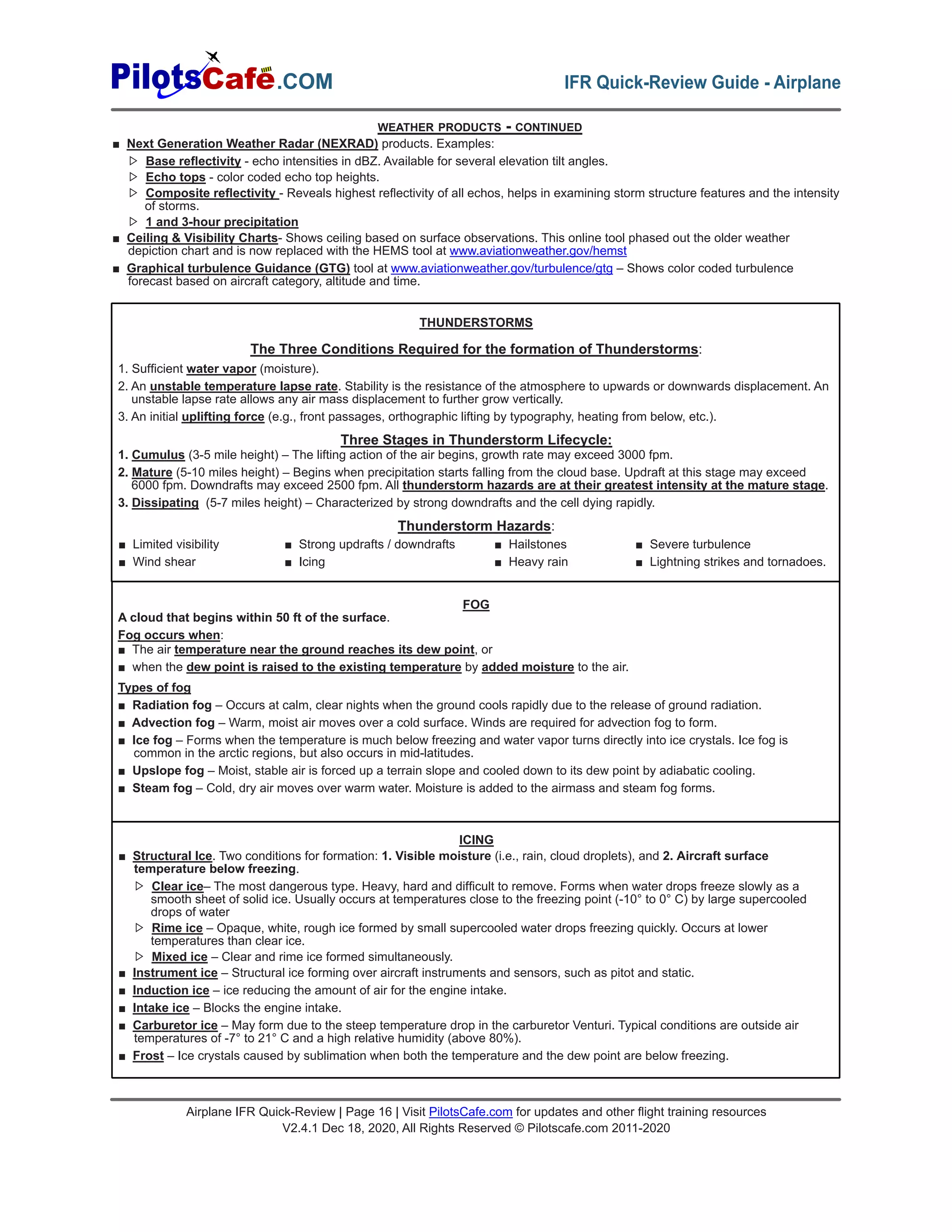
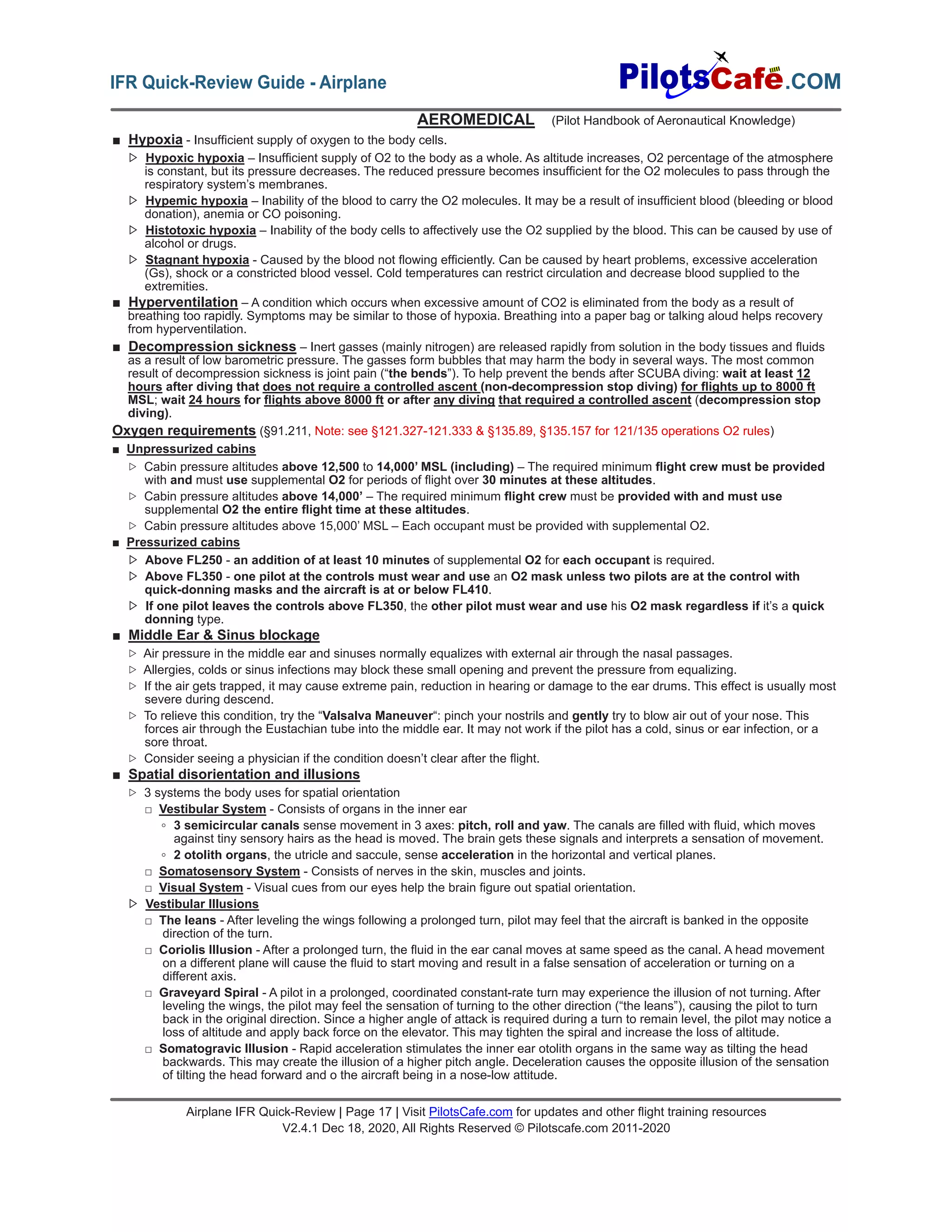
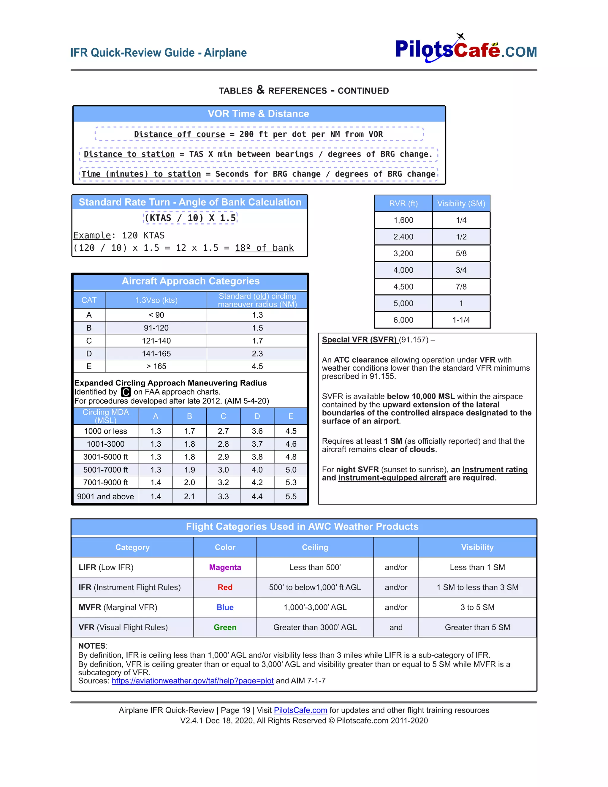
SlideShare a Scribd company logo
AIRPLANE-INSTRUMENT RATING MINIMUM
AERONAUTICAL EXPERIENCE
■ 50 hours X-Country PIC time
▷ Of which ,10 hours in airplanes.
■ 40 hours actual or simulated instrument time
▷ Of which, 15 hours with CFII.
□ Including one X-Country flight of:
□ 250 NM along airways or by directed ATC
routing.
□ An instrument approach at each airport.
□ 3 different kinds of approaches using
navigation systems.
□ With a filed IFR flight plan.
□ 3 Hours instrument flight training in last 2 Calendar
months prior to practical test
■ Use of approved full flight simulator or FTD, if trained by
authorized instructor:
▷ Max. 30 hours if instrument time completed under
part 142
▷ Max 20 hours if not completed under 142
■ Use of FAA approved Aviation Training Device, if trained
by an authorized instructor:
▷ Max.10 hours of instrument time if Basic ATD
▷ Max. 20 hours of instrument time if Advanced ATD
■ No more than 20 hours of total instrument time can be
credited in a full flight simulator, FTD or ATD, except the
30 hours exception under part 142 mentioned above.
§61.65
PERSONAL DOCUMENTS REQUIRED FOR
FLIGHT
■ Pilot Certificate
■ Medical certificate (or US Driver’s license as
permitted by §61.113 & §61.23)
■ Authorized photo ID (passport, driver’s license, etc)
■ Restricted Radiotelephone Operator Permit (For
flights outside the US)
RECENCY OF EXPERIENCE
■ To act as PIC under IFR or in weather conditions
less than the minimums for VFR- “6 HITS” –
Within 6 cal. months preceding the month of
flight:
▷ 6 instrument approaches
▷ Holding procedures & tasks
▷ Intercepting & Tracking courses through the use
of navigational electronic systems
▷ The above can be completed in a FFS, ATD, or
FTD provided the device represents the category of
aircraft for the instrument rating privileges to be
maintained and the pilot performs the tasks and
iterations in simulated instrument conditions. A
flight instructor is not needed
■ Not current looking back 6 months?
You can still log the required “6 HITS” with a safety pilot
(under simulated conditions), examiner or instructor.
▷ Safety pilot requirements
□ At least a private pilot with appropriate category
and class.
□ Have adequate vision forward and to each side of
the aircraft.
□ Aircraft must have a dual control system.
■ Not current looking back 12 months?
▷ Instrument Proficiency Check (IPC) by a CFII,
examiner, or other approved person is required.
Guidelines are in the ACS.
▷ Some IPC tasks, but not all, can be conducted in a
FTD or ATD. (Refer to the ACS)
■ To carry passengers as PIC
▷ 3 takeoffs & landings in category, class and type
(if type rating req.) In the last 90 days.
▷ At periods between 1 hour after sunset to 1 hour
before sunrise: 3 takeoffs & landings to full stop
within 1 hour after sunset to 1 hour before sunrise.
■ To act as PIC - Flight review in the last 24
Calendar months (see FAR for exceptions).
(§61.56, §91.109, §61.57, Instrument- Airplane ACS) §61.3, §61.113, §61.23, ICAO Article 29
LOGGING INSTRUMENT TIME §61.51
Airplane IFR Quick-Review | Page 1 | Visit PilotsCafe.com for updates and other flight training resources
V2.4.1 Dec 18, 2020, All Rights Reserved © Pilotscafe.com 2011-2020
.COM
IFR Quick-Review Guide - Airplane
Airplane IFR Quick-Review
A person may log instrument time
only for that flight time when the
person operates the aircraft solely by
reference to instruments under actual
or simulated instrument flight
conditions.
An authorized instructor may log
instrument time when conducting
instrument flight instruction in actual
instrument flight conditions.
To meet recent instrument
experience requirements, the
following information must be recorded
in the person's logbook:
■ Location & type of each instrument
approach accomplished, and
■ The name of the safety pilot, if
required
Use of full flight simulator, FTD, or
ATD for acquiring instrument
aeronautical experience:
■ For training towards a certificate or
rating, an authorized instructor is
present to observe and signs the
person’s logbook to verify the time
and content of the session.
■ For IFR recency requirements, log:
▷ Training device, time and content.
AIRCRAFT DOCUMENTS REQUIRED FOR
FLIGHT
A.R.R.O.W –
A - Airworthiness certificate
R - Registration certificate
R - Radio station license (for flights outside the US)
O - Operating limitations & information (in AFM)
W - Weight & Balance data (aircraft specific)
(§21.5, §91.103, §91.9, §91.203, ICAO Article 29)
AIRCRAFT MAINTENANCE INSPECTIONS
REQUIRED FOR IFR:
A.V.I.A.T.E.S –
■ A - Airworthiness Directive (AD) required inspections.
(§39)
■ V - VOR check every 30 days. (For IFR; §91.171)
■ I - Inspections: (§91.409)
▷ Annual inspection - 12 Cal. Months (all aircraft).
▷ 100-hour (time-in-service) inspection required if:
□ Carrying a person for hire (other than crew
member), or
□ Flight instructing for hire in an aircraft provided by
the person giving the instruction.
□ “For hire” refers to the person , not the aircraft.
◦ Flight school providing airplane + instructor for hire:
100-hours required
◦ Student-owned aircraft: 100-hours not required.
◦ Rental (no pilot or instructor): 100-hr not required.
□ The 100-hr inspection may be exceeded by up to 10
hours if aircraft is enroute to a place where it can be
done. This additional time must be included in
computing the next 100-hours inspection.
□ An annual inspection can substitute for the 100-hour if
done within 100 hours of time-in-service.
▷ A progressive inspection schedule, if specifically
approved by the FAA, may replace the annual and 100
hour inspections.
■ A - Altimeter, automatic altitude reporting (used by
transponder) & static system every 24 calendar months.
(For IFR in controlled airspace; §91.411)
■ T - Transponder every 24 calendar months. (§91.413)
■ E - ELT (§91.207)
▷ inspected every 12 calendar months.
▷ Battery must be replaced after more than 1 hour of
cumulative transmitter use or if 50% of its useful life
has expired (or, for rechargeable batteries, 50% of the
useful life of charge has expired).
■ S - Supplemental Type Certificate (STC) required
inspections.
PREFLIGHT SELF-ASSESSMENT:
I.M S.A.F.E –
■ I - Illness - Do I have any symptoms?
■ M - Medication - Have I taken prescription or over-the-
counter drugs?
■ S - Stress - Am I under psychological pressure, worried
about finances, health or family discord?
■ A - Alcohol - No drinking within 8 hours. (“8 hours bottle to
throttle”). No more than .04% of alcohol in blood.
■ F - Fatigue - Am I tired / adequately rested?
■ E - Emotion - Am I emotionally upset?
(§91.17, AIM 8-1-1)
PREFLIGHT INFO REQUIRED FOR IFR:
N.W K.R.A.F.T – (§91.103)
■ N - NOTAMs.
■ W - Weather reports and forecasts.
■ K - Known traffic delays as advised by ATC.
■ R - Runway length of intended use.
■ A - Alternatives available if flight cannot be completed as
planned.
■ F - Fuel requirements
■ T - Takeoff and landing performance data.
RISK MANAGEMENT & PERSONAL MINIMUMS
P.A.V.E –
■ P - Pilot (general health, physical / mental / emotional state,
proficiency, currency)
■ A - Aircraft (airworthiness, equipment, performance)
■ V - EnVironment (weather hazards, terrain, airports /
runways to be used & other conditions)
■ E - External pressure (meetings, people waiting at
destination, etc.)
(Pilot’s Handbook of Aeronautical Knowledge)
DECISION MAKING
D.E.C.I.D.E –
■ D - Detect that a change has occurred.
■ E - Estimate the need to counter the change.
■ C - Choose a desirable outcome.
■ I - Identify solutions.
■ D - Do the necessary actions.
■ E - Evaluate the effects of the actions
(Pilot’s Handbook of Aeronautical Knowledge)
PASSENGER BRIEFING
S.A.F.E.T.Y –
■ S
▷ Seat belts fastened for taxi, takeoff, landing.
▷ Shoulder harness fastened for takeoff, landing.
▷ Seat position adjusted and locked in place
■ A
▷ Air vents location and operation
▷ All environmental controls (discussed)
▷ Action in case of any passenger discomfort
■ F
▷ Fire extinguisher (location and operation)
■ E
▷ Exit doors (how to secure; how to open)
▷ Emergency evacuation plan
▷ Emergency/survival kit (location and contents)
■ T
▷ Traffic (scanning, spotting, notifying pilot)
▷ Talking, sterile flight deck expectations
■ Y
▷ Your questions? Speak up!
(Pilot’s Handbook of Aeronautical Knowledge)
TAXI BRIEFING
A.R.C.H –
■ A - Assigned / planned runway.
■ R - Route.
■ C - Crossings and hold short instructions.
■ H - Hot spots & Hazards (e.g., NOTAMs, closed taxiways/
runways, surface condition).
Airplane IFR Quick-Review | Page 2 | Visit PilotsCafe.com for updates and other flight training resources
V2.4.1 Dec 18, 2020, All Rights Reserved © Pilotscafe.com 2011-2020
.COM IFR Quick-Review Guide - Airplane
Airplane IFR Quick-Review | Page 3 | Visit PilotsCafe.com for updates and other flight training resources
V2.4.1 Dec 18, 2020, All Rights Reserved © Pilotscafe.com 2011-2020
.COM
IFR Quick-Review Guide - Airplane
TAKEOFF BRIEFING
D.E.P.A.R.T.S –
D - Departure review (e.g. takeoff type, initial heading, first fix &
course, clearance readout).
E - Establish Expectations (e.g., flying pilot, PIC, positive
transfer of controls).
P - Plan / special considerations (e.g., weather, visibility, terrain,
unfamiliar field, inoperative equipment / MELs).
A - Alternate (takeoff alternate, if needed, or return plan)
R - Runway conditions and length.
T - Trouble / Tactics (e.g., rejected takeoff, engine failure).
S - Speak up! Questions / concerns?
IFR FLIGHT PLAN
■ Requirement: no person may operate an aircraft in controlled
airspace under IFR unless that person has:
▷ Filed an IFR flight plan; and
▷ Received an appropriate ATC clearance.
■ It is legal to fly IFR in uncontrolled airspace (class G)
without a flight plan or clearance. However, once airborne,
you must remain in uncontrolled airspace until you file a
flight plan and get an ATC clearance to enter the controlled
airspace.
§91.173
■ How to file an IFR flight plan?
▷ FSS
□ by phone (1-800-WX-BRIEF)
■ over the radio (GCO/RCO frequencies)
□ In person.
▷ Online
□ www.1800wxbrief.com (Leido)
□ www.fltplan.com (Garmin)
▷ EFB (e.g., Foreflight)
▷ With ATC (over radio, or phone if no other mean available)
■ File at least 30 minutes prior to estimated departure. Non-
scheduled flights above FL230 should be filed at least 4
hours before est. departure time. (AIM 5-1-8)
■ Flight plan cancelation (AIM 5-1-15)
▷ Towered airports - automatically cancelled by ATC upon
landing.
▷ Non-towered airports - Pilot must contact ATC / FCC to
cancel (by radio or phone)
▷ Can cancel anytime in flight if out of IMC and out of
class A airspace.
■ Preferred IFR Routes are published in the Chart Supplement
U.S. It is to the pilot’s advantage to file a preferred route if
available. (AIM 5-1-8)
NEED A DESTINATION ALTERNATE?
“1-2-3” RULE –
A destination alternate is always required, unless:
■ An instrument approach is published and
available for the destination, AND,
■ For at least 1 hour before to 1 hour after ETA:
▷ Ceiling will be at least 2000’ above airport
elevation; and
▷ Visibility will be at least 3 SM.
§91.169
MIN WX CONDITIONS REQUIRED AT AN AIRPORT
TO LIST IT AS AN ALTERNATE
The alternate airport minima published in the
procedure charts, or, if none:
■ Precision approach:
600 ft ceiling and 2 SM visibility.
■ Non-precision approach:
800 ft ceiling and 2 SM visibility.
■ No instrument approach available at the
alternate:
Ceiling & visibility must allow descent from MEA,
approach and landing under VFR.
§91.169
FILING AN ALTERNATE - GPS CONSIDERATIONS
■ Equipped with a non-WAAS GPS? You can flight
plan based on GPS approaches at either the
destination or the alternate, but not at both.
■ WAAS Without baro-VNAV? May base the flight
plan on use of LNAV approaches at both the
destination and alternate.
■ WAAS with baro-VNAV? May base the flight plan
on use of LNAV/VNAV or RNP 0.3 at both the
destination and the alternate.
AIM 1-1-17b.5, 1-1-18c.9, 1-2-3d
YES
N
180-359º
EVEN
0-179º
ODD
IFR CRUISING ALTITUDES §91.179
Uncontrolled airspace –
Based on magnetic course:
Below FL290
0º-179º ODD thousands (below 18,000’)
or Flight Levels (at or above FL180)
180º-359º EVEN thousands (below 18,000’) or Flight
Levels (at or above FL180)
Above FL290 (in non-RVSM)
0º-179º Flight Levels at 4,000’ increments starting at
FL290 (e.g., FL 290, 330, 370)
180º-359º Flight Levels at 4,000’ increments starting at
FL310 (e.g., FL 310, 350, 390)
Above FL290-FL410 (in RVSM)
0º-179º Odd Flight Levels at 2,000’ intervals starting at
FL290 (e.g., FL 290, 310, 330)
180º-359º Even Flight Levels at 2,000’ intervals starting
at FL300 (e.g., FL 300, 320, 340)
Controlled airspace –
IFR Cruising altitudes are as assigned by ATC.
IFR MINIMUM FUEL REQUIREMENTS §91.167
45 Minutes
calculated
at
normal
cruise
Fuel from
destination to
most distant
alternate
(if alternate required)
Fuel from
departure to
destination
airport
*Other fuel requirements exist for 121, 135, Flag and supplemental operations
+ +
IFR TAKEOFF MINIMUMS (§91.175)
No T/O minimums mandated for part 91 operations.
Part 121, 125, 129, 135:
■ Prescribed T/O minimums for the runway, or, if none:
■ 1-2 engines airplanes: 1 SM visibility
■ More than 2 engines: ½ SM visibility
Non-Standard TO mins / Departure Procedures.
Non-Standard IFR alternate minimums exist.
Alternate minimums not authorized due to
unmonitored facility or the absence of weather
reporting service.
DEPARTURE PROCEDURES (DP)
AIM 5-2-9
■ Either textual or graphical.
■ Ensures obstacle clearance, provided:
▷ the airplane crossed the departure end of the
runway at least 35 ft AGL,
▷ reaches 400 ft AGL before turning, and
▷ climbs at least 200 Feet per NM (FPNM), or as
published otherwise on the chart.
□ FPNM to feet-per-minute conversion:
fpm = FPNM * Groundspeed / 60
■ Pilots are encouraged to file a DP at night, during
marginal VMC or IMC.
■ Two types of DP
▷ Obstacle Departure Procedure (ODP)
□ Provides only obstacle clearance.
□ Graphic ODPs will have “(OBSTACLE)”
printed in the chart title.
▷ Standard Instrument Departure (SID)
□ In addition to obstacle clearance it reduces
pilot and controller workload by simplifying
ATC clearances and minimizing radio
communications.
□ Some SIDs may depict special radio failure
procedures.
■ DP are also categorized by equipment required:
▷ Non-RNAV DP - for use by aircraft equipped with
ground-based navigation (i.e., VOR, DME, NDB).
▷ RNAV DP - for aircraft equipped with RNAV
equipment (e.g., GPS, VOR/DME, DME/DME).
Require at least RNAV 1 performance. Identified
with the word “RNAV” in the title.
▷ RADAR DP - ATC radar vectors to an ATS route,
NAVAID, or fix are used after departure. RADAR
DPs are annotated “RADAR REQUIRED.”
■ You are not required to accept a DP. To avoid
receiving one, state “NO SIDs” in remarks section
of flight plan.
■ Transition routes connect the end of the basic SID
procedure to the en route structure.
IFR DEPARTURE CLEARANCE
C.R.A.F.T –
■ C - Clearance limit.
■ R - Route.
■ A - Altitude.
■ F - Frequency (for departure).
■ T - Transponder code.
Clearance void time – The time at which your
clearance is void and after which you may not takeoff.
You must notify ATC within 30 min after the void time if
you did not depart.
“Hold for release” – You may not takeoff until being
released for IFR departure.
Release time – The earliest time the aircraft may
depart under IFR.
Expect Departure Clearance Time (EDCT) – A
runway release time given under traffic management
programs in busy airports. Aircraft are expected to
depart no earlier and no later than 5 minutes from the
EDCT.
Abbreviated departure clearance – “Cleared (...) as
filed (...)”
(AIM 5-2-6)
STANDARD TERMINAL ARRIVAL (STAR)
■ Serves as a transition between the en route
structure and a point from which an approach to
landing can be made.
■ Transition routes connect en route fixes to the
basic STAR procedure.
■ Usually named according to the fix at which the
basic procedure begins.
■ As with a SID, you can state “NO STARs” in the
remarks section of the flight plan, to avoid getting a
clearance containing a STAR.
■ RNAV STARs require RNAV 1 performance.
IFR ALTITUDES
MIN IFR ALTITUDES (§91.177)
■ Except for takeoff or landing, or otherwise authorized
by the FAA, no person may operate an aircraft under
IFR below -
▷ Minimum altitudes prescribed for the flown
segment, or if none:
▷ Mountainous areas: 2,000 ft above the highest
obstacle within a horizontal distance of 4 NM
from the course.
▷ Non-mountainous areas: 1,000 ft above the
highest obstacle within 4 NM from the course.
NA
Airplane IFR Quick-Review | Page 4 | Visit PilotsCafe.com for updates and other flight training resources
V2.4.1 Dec 18, 2020, All Rights Reserved © Pilotscafe.com 2011-2020
.COM IFR Quick-Review Guide - Airplane
Airplane IFR Quick-Review | Page 5 | Visit PilotsCafe.com for updates and other flight training resources
V2.4.1 Dec 18, 2020, All Rights Reserved © Pilotscafe.com 2011-2020
.COM
IFR Quick-Review Guide - Airplane
IFR ALTITUDES - CONTINUED (§91.177, Pilot/Controller Glossary)
■ DA / H - Decision Altitude / Height: the Altitude (MSL) / Height (above runway threshold), on an instrument approach procedure
at which the pilot must decide whether to continue the approach or go around.
■ MAA - Maximum Authorized Altitude. Annotated “MAA-17000” (17,000ft as an example) on IFR charts.
■ MCA - Minimum Crossing Altitude
■ MDA / H - Minimum Decent Altitude / Height: The lowest Altitude (MSL) / Height (above runway threshold) to which descent is
authorized on a non-precision approach until the pilot sees the visual references required for landing.
■ MEA - Minimum En route Altitude: The lowest published altitude between radio fixes which assures acceptable navigational
signal coverage and meets obstacle clearance requirements. An MEA gap establishes an area of loss in navigational coverage
and annotated “MEA GAP” on IFR charts.
■ MOCA - Minimum Obstruction Clearance Altitude: Provides obstacle clearance and navigation coverage only up to 22 NM of
the VOR.
▷ If both an MEA and a MOCA are prescribed for a particular route segment, a person may operate an aircraft lower than
the MEA down to, but not below the MOCA, provided the applicable navigation signals are available. For aircraft
using VOR for navigation, this applies only when the aircraft is within 22 NM of the VOR. (§91.177)
■ MORA - Minimum Off Route Altitude (Jeppesen):
▷ Route MORA provides obstruction clearance within 10NM to either side of airway centerlines and within a 10NM radius at
the ends of airways.
▷ Grid MORA provide obstruction clearance within a latitude / longitude grid block.
■ MRA - Minimum Reception Altitude
■ MTA - Minimum Turning Altitude: Provides vertical and lateral obstacle clearance in turns over certain fixes. Annotated with the
MCA X icon and a note describing the restriction.
■ MVA - Minimum Vectoring Altitude: The lowest altitude at which an IFR aircraft will be vectored by a radar controller, except as
otherwise authorized for radar approaches, departures, and missed approaches. MVAs may be lower than the minimum
altitudes depicted on aeronautical charts, such as MEAs or MOCAs.
■ OROCA - Off Route Obstruction Clearance Altitude: Provides obstruction clearance with a 1,000 ft buffer in non-mountainous
terrain areas and 2,000 ft in mountainous areas. OROCA may not provide navigation or communication signal coverage.
*Designated mountainous areas are defined in 14 CFR part 95 by lat / long coordinates.
V4
16000
11700G
*11000
125
OROCA MEA
MRA
MCA /
MTA
GPS MEA
MOCA
GYROSCOPIC INSTRUMENTS
■ Two principles of a gyroscope: Rigidity in space and precession.
■ Attitude indicator – operates on the principle of rigidity in space. Shows bank and pitch information. Older AIs may have a
tumble limit. Should show correct attitude within 5 minutes of starting the engine. Normally vacuum-driven in GA aircraft, may
be electrical in others. May have small acceleration/deceleration errors (accelerate-slight pitch up, decelerate- pitch down) and
roll-out errors (following a 180 turn shows a slight turn to the opposite direction).
■ Heading indicator – operates on the principle of rigidity in space. It only reflects changes in heading, but cannot measure the
heading directly. You have to calibrate it with a magnetic compass in order for it to indicate correctly. HIs may be slaved to a
magnetic heading source, such as a flux gate, and sync automatically to the present heading. Normally powered by the
vacuum system in on GA aircraft.
■ Turn indicators – operates on the principle of precession.
▷ Turn coordinators show rate-of-turn and rate of roll.
▷ Turn-and-slip indicators show rate-of-turn only.
ALTIMETER
■ An aneroid barometer that shows the height above a given pressure level, based on standard pressure lapse rate of 1000’ per
inch of mercury.
■ A stack of sealed aneroid wafers expand and contract with changes in atmospheric pressure received from the static port.
■ A mechanical linkage between the aneroid and the display translates the sensed pressure to an altitude indication.
■ An altimeter setting knob (on a “sensitive altimeter”, which are most aircraft altimeters) allows the pilot to adjust the current
pressure to the current altimeter setting published locally (available from ATIS, METAR or ATC).
■ The pressure setting is displayed in the “Kollsman Window” in mb and/or inches of mercury (Hg)
■ In the US, when operating below 18,000’ MSL regularly set the altimeter to a station within 100 NM. Above 18,000’ MSL,
the altimeter should be set to the standard sea level pressure of 29.92” Hg, and operate in Flight Levels (FL).
■ “High to Low - Watch out below!”. Use caution when flying from high pressure to low pressure areas. If altimeter setting is not
updated, altitude will indicate higher, causing the pilot to fly lower than desired. Flying from hot to cold areas results in the
same error.
FLIGHT INSTRUMENTS
PITOT-STATIC INSTRUMENTS
TYPES OF ALTITUDES
■ Indicated altitude – Uncorrected altitude indicated on the dial when set to local pressure setting (QNH).
■ Pressure altitude – Altitude above the standard 29.92. Hg plane. (QNE). Used when flying above the transition altitude
(18,000’ in the US)
■ Density altitude – Pressure alt. corrected for nonstandard temperature. Used for performance calculations.
■ True altitude – Actual altitude above Mean Sea Level (MSL).
■ Absolute altitude – Height above airport elevation (QFE).
TYPES OF SPEEDS
■ Indicated airspeed (IAS) – indicated on the airspeed indicator
■ Calibrated airspeed (CAS) – IAS corrected for instrument & position errors.
■ Equivalent airspeed (EAS) – CAS corrected for compressibility error.
■ True airspeed (TAS) – Actual speed through the air. EAS corrected for nonstandard
temperature and pressure
■ Mach number – The ratio of TAS to the local speed of sound.
■ Ground speed – Actual speed over the ground. TAS corrected for wind conditions.
AIRSPEED INDICATOR (ASI)
■ The airspeed indicator measures the difference between impact (ram) air pressure from the pitot tube and ambient pressure
from the static port. The result pressure is called dynamic pressure and corresponds to airspeed.
▷ Dynamic Pressure (airspeed) = Impact Pressure – Static pressure.
■ A diaphragm in the instrument receives ram pressure from the pitot tube. The area outside the diaphragm is sealed and
connected to the static port. A mechanical linkage converts the expansion and contraction of the diaphragm to airspeed shown
on the display dial.
AIRSPEED INDICATOR MARKINGS
■ White arc - Flap operating
range. Starts at Vs0; ends at
Vfe
■ Green arc - Normal operating
range.Starts at Vs1; ends at Vno
■ Yellow arc - Caution range. Fly
only in smooth air and only with
caution.
■ Red line - Vne
V-SPEEDS
■ Va - Design maneuvering speed
■ Vs - Stall speed, clean config.
■ Vs0 - Stall speed landing config.
■ Vs1 - Stall speed specific config.
■ Vfe - Max flap extended speed.
■ Vno - Max structural cruise
speed
■ Vne - Never Exceed Speed
■ Vx - Best angle of climb
■ Vy - Best rate of climb
STATIC PORT BLOCKAGE
■ Airspeed indicator – Indicates correctly only at the blockage altitude.
▷ Higher altitudes → airspeed indicates lower than it should.
▷ Lower altitudes → Indicates higher than it should.
■ Altimeter – will freeze on the altitude where it was blocked.
■ VSI – freezes on zero.
▷ After verifying a blockage in the static port, you should use an alternate static source
or break the VSI window (in which case, expect reverse VSI information).
■ When using the alternate static source (a lower static pressure is measured):
▷ Airspeed indicator – indicate a faster speed than it should.
▷ Altimeter – indicate higher than it should.
▷ VSI – momentarily show a climb.
PITOT TUBE BLOCKAGE
The only instrument affected is the airspeed indicator.
■ Ram air inlet clogged and drain hole open? Airspeed drops to zero.
■ Both air inlet and drain hole are clogged? The airspeed indicator will act as an altimeter, and will no longer be reliable.
■ When suspecting a pitot blockage, consider the use of pitot heat to melt ice that may have formed in or on the pitot tube.
■ Airspeed – 0 KIAS.
■ Turn coordinator – ball centered and wings level when not
turning. On turns: shows turn in correct direction, ball goes to
opposite direction of the turn.
■ Attitude – Correct pitch attitude and bank angle ±°5 within 5
minutes of engine start (if vacuum).
■ Heading indicator – Set and shows correct headings.
■ Altimeter – Set to local altimeter settings or to airport elevation
(§91.121). Shows surveyed elevation ±75 ft (AIM 7-2-3).
■ VSI – 0 fpm.
■ Magnetic compass – swings freely, full of fluid, shows
known headings and deviation card is installed. Marker
beacons – Tested.
■ NAV & Comm – Set.
■ GPS – Checked and set.
■ EFIS cockpits – Check PFD/MFD/EICAS for ‘X’s,
messages, warnings and removed symbols.
GENERIC INSTRUMENT TAXI CHECK
VERTICAL SPEED INDICATOR (VSI)
■ Indicates rate-of-climb in fpm (accurate after a 6-9 sec. lag), and rate trend (immediately with rate change).
■ A diaphragm inside the instrument is connected directly to the static source.
■ The area outside the diaphragm also receives static pressure, but via a calibrated leak (a restricted orifice).
■ This configuration essentially responds to static pressure change over time.
■ As the diaphragm expands or contracts, a mechanical linkage moves the pointer needle to display the current rate of climb to
the pilot.
■ Instantaneous VSI (IVSI) solves the lag issue with the addition of vertical accelerometers.
Airplane IFR Quick-Review | Page 6 | Visit PilotsCafe.com for updates and other flight training resources
V2.4.1 Dec 18, 2020, All Rights Reserved © Pilotscafe.com 2011-2020
.COM IFR Quick-Review Guide - Airplane
For VFR day:
A T.O.M.A.T.O F.L.A.M.E.S –
A - Altimeter
T - Tachometer for each engine.
O - Oil temperature indicator for each engine.
M - Manifold pressure gauge for each altitude engine.
A - Airspeed indicator.
T - Temperature gauge for each liquid cooled engine.
O - Oil pressure gauge for each engine.
F - Fuel quantity gauge for each tank.
L - Landing gear position lights (if retractable gear).
A - Anticollision lights (for aircraft certified after March
11, 1996).
M - Magnetic direction indicator (magnetic compass).
E - ELT, if required by §91.207.
S - Safety belt / shoulder harness.
For VFR night:
All VFR day equipment + FLAPS
F.L.A.P.S –
F - Fuses (spare set).
L - Landing light (if for hire) .
A - Anticollision lights.
P - Position lights (navigation lights).
S - Source of electrical power (i.e., battery).
If operating for hire over water and beyond power-off
gliding distance from shore: (unless part 121)
■ An approved floatation device for each occupant
■ At least one pyrotechnic signaling device
Flight at and above FL240:
When using VOR for navigation, DME or RNAV is also
required.
For IFR day: all VFR day equipment + GRABCARD
For IFR night: all VFR day + VFR night + GRABCARD
G.R.A.B.C.A.R.D –
G - Generator / alternator.
R - Radios. Two-way radio communication & navigational equipment
suitable for the route to be flown.
A - Altimeter (sensitive, adjustable for barometric pressure)
B - Ball (slip-skid indicator).
C - Clock. Shows hours, minutes and seconds with sweep-second
pointer or digital representation. Installed as part of aircraft
equipment.
A - Attitude indicator.
R - Rate-of-turn indicator.
D - Directional gyro (heading indicator).
OPERATING WITH INOPERATIVE ITEMS (§91.213)
Aircraft has an
MEL?
Is the inoperative equipment required by:
■ VFR-day type certification requirements?
■ Equipment list or kind of operations equipment list?
■ §91.205 or other regulations for kind of operations?
■ An Airworthiness Directive (AD)?
Flying is permitted, provided:
■ Inoperative equipment is removed, or
■ deactivated and placarded “Inoperative.”
■ Pilot/mechanic determines no hazard from inop. item.
Flying not allowed without a
special flight permit
Follow MEL
provisions
Yes
No
No
Yes
MINIMUM EQUIPMENT REQUIRED FOR FLIGHT (§91.205)
MAGNETIC COMPASS ERRORS & LIMITATIONS – D.V M.O.N.A
■ D- Deviation
■ V- Variation
■ M- Magnetic dip
■ O- Oscillation
■ N- North/south turn errors -
Northern hemisphere: UNOS Undershoot North/ Overshoot South
■ A- Acceleration errors -
Northern hemisphere: ANDS Accelerate North/ Decelerate South
ELECTRONIC FLIGHT INSTRUMENTS
■ Attitude Heading Reference Systems (AHRS) – Provides more accurate and reliable attitude and heading data than
traditional separate gyro systems. The first AHRS units were very expensive and relied on laser gyros and flux valves. Today
they are based on solid state technologies (no moving parts) and are cheaper, smaller and easier to maintain.
■ Air Data Computers (ADC) – replaces the mechanical pitot-static instruments. The ADC receives inputs from the pitot, static
and outside temperature ports and computes airspeed, true airspeed, vertical speed and altitude.
■ Flight director – computes and displays command bars over the attitude indicator to assist the pilot in flying selected heading,
course or vertical speed.
■ Flight Management System (FMS) – Receives inputs from various sensors and provides guidance to the autopilot and flight
director throughout the flight. The FMS also automatically monitors and selects the most appropriate navigation source for
accurate positioning. (GPS, VOR/DME, INS etc.)
■ Electronic Flight Instrument Systems (EFIS) – AKA “Glass cockpit”.
■ Primary Flight Displays (PFD) – Displays flight data such as attitude, altitude, airspeed, VSI and heading as well as rate
tapes.
■ Multi-Function Displays (MFD) – Displays a variety of information such as moving maps, aircraft system status, weather and
traffic. It may also be used as a backup for other displays, such as the PFD or EICAS.
Airplane IFR Quick-Review | Page 7 | Visit PilotsCafe.com for updates and other flight training resources
V2.4.1 Dec 18, 2020, All Rights Reserved © Pilotscafe.com 2011-2020
.COM
IFR Quick-Review Guide - Airplane
DISTANCE MEASURING EQUIPMENT
(DME)
■ 962-1213 MHz (UHF).
■ Normally tuned automatically with a
paired VHF station (VOR/LOC).
■ The Airborne DME unit transmits an
interrogation signal.
■ The ground DME facility receives and
replies to the interrogation.
■ Airborne unit calculates the slant range
distance to the station based on the
reply time.
■ Due to slant range error, when flying
overhead the station, DME indication is
not “0”.
■ Slant range error is negligible at 1 NM
from the DME station per every 1000ft.
For example, at 5000 ft, slant range
error is negligible when further than 5
NM of the station.
RADIO NAVIGATION
NON-DIRECTIONAL BEACON (NDB)
■ Operates at the 190-535 kHz range (can receive and point towards commercial
radio AM station at 550 -1650 kHz).
■ Low to medium frequency band.
■ ADF (Automatic Direction Finder) in aircraft points towards the NDB station.
■ Magnetic Bearing = Magnetic Heading + Relative Bearing
COMPASS LOCATOR
A low-powered NDB transmitter (at least 25 Watts and 15NM range) installed at the
OM or the MM on some ILS approaches.
NDB Service Volume Classes
Compass Locator 15 NM
Medium High (MH) 25 NM
High (H)
50 NM (or less, as published in NOTAM or
Chart Supplement)
High High (HH) 75 NM
AREA NAVIGATION (RNAV)
■ Allows navigation on any desired path without the
need to overfly ground-based facilities.
■ Types:
▷ Global Navigation Satellite System (GNSS)
(e.g., GPS, Galileo, GLONASS, BeiDou)
▷ VOR/DME RNAV
▷ DME/DME RNAV
▷ Inertial Reference Unit / System (IRU/ IRS)
■ RNAV VNAV - Vertical NAVigation guidance.
■ BARO-VNAV - An RNAV system that uses the
barometric altitude to compute vertical guidance for
the pilot.
■ Published RNAV routes include Q (FL180 to FL450)
and T (1,200 AGL to 18,000 MSL) routes and are
designated RNAV 1 unless charted otherwise.
■ Magnetic Reference Bearing (MRB) - the published
bearing between two waypoints on an RNAV route.
REQUIRED NAVIGATION PERFORMANCE (RNP)
■ RNP is:
▷ A statement of navigation equipment and service
performance.
▷ RNAV with navigation monitoring and alerting.
■ All RNAV approaches are RNP approaches
▷ Most US RNP approaches are titled “RNAV (GPS)”.
▷ US Approaches with “RNAV (RNP)” in the title are “AR”
(Authorization Required) approaches, which require special
FAA approval for the crew, aircraft and operation.
▷ In other countries, all RNP approaches may have “RNP” in the
title, even those that do not require special authorization.
RNP approach minimas and equipment:
■ GLS DA minimas using GBAS (formerly LAAS)
■ LP MDA or LPV DA minimas require RNP achieved by WAAS.
■ LNAV / VNAV DA achieved by VNAV-approved WAAS, or BARO-
VNAV systems.
■ LNAV MDA - achieved by a basic, unaugmented IFR-approved GPS.
25
NM
12,000 ft
Terminal
1,000 ft
5,000 ft (new)
70
NM (new under MON)
40
NM
18,000 ft
Low
1,000 ft
5,000 ft (new)
70 NM (new – MON)
18,000 ft
45,000 ft
60,000 ft
14,500 ft
1,000 ft
High
100
NM
130
NM
40
NM
100
NM
STANDARD VOR SERVICE VOLUMES
VHF OMNI DIRECTIONAL RANGE (VOR)
■ 108.0 to 117.95 MHz, excluding 108.10-111.95 with odd tenths (reserved for LOC
frequencies).
■ Full scale deflection: 10º.
■ Standard service volumes do not apply to published routes.
■ Pilot must verify correct and usable VOR station with morse ID before using it.
■ The VOR MON (VOR Minimum Operational Network) program ensures that as old
VORs are decommissioned, a MON airport (i.e.,equipped with legacy ILS or VOR
approach) is available within 100 NM regardless of aircraft position in the CONUS.
VOR limitations
■ Cone of confusion
■ Reverse sensing (if used incorrectly)
■ Requires line-of-sight between
aircraft and station.
VOR Receiver Checks (§91.171)
■ Perform every 30 calendar days
▷ VOT ±4º
▷ Repair Station ±4º
▷ VOR ground checkpoint ±4º
▷ VOR airborne checkpoint ±6º
▷ Dual VOR cross-check ±4º
▷ Above a prominent ground
landmark on a selected radial at
least 20 NM from a VOR, flying
at a “reasonable low altitude” ±6º
VOR Check sign-off (§91.171)
D.E.P.S –
D - Date
E - Error (bearing error)
P - Place
S - Signature
Airplane IFR Quick-Review | Page 8 | Visit PilotsCafe.com for updates and other flight training resources
V2.4.1 Dec 18, 2020, All Rights Reserved © Pilotscafe.com 2011-2020
.COM IFR Quick-Review Guide - Airplane
GLOBAL POSITIONING SYSTEM (GPS)
■ GPS is a Global Navigation Satellite System (GNSS) operated by the United States.
■ The constellation consists of a minimum of 24 satellites (with some spares) orbiting above the earth at 10,900 NM. The system
is designed so that at least 5 satellites are in view at any given location on earth.
■ The Aircraft’s GPS receiver calculates the distance to a GPS satellite based on the time lapse since the broadcast timestamp
(obtained from an atomic clock onboard the satellite) and the time it received the signal.
■ Using only one satellite, the aircraft could virtually be on any point on a sphere surrounding the satellite, with the calculated
distance (“pseudo-range”) as the sphere’s radius.
■ The GPS receiver uses the intersection of spheres, from multiple satellites, to calculate the aircraft’s geographical position.
Course and speed data are computed from aircraft position changes.
■ At least 3 satellites are required for 2D position. (latitude and longitude); at least 4 satellites are required for 3D position.
(latitude, longitude and altitude).
■ Receiver Autonomous Integrity Monitoring (RAIM) is a function of GPS receivers that monitors the integrity of the satellite
signals.
▷ RAIM (fault detection) requires a minimum of 5 satellites, or, 4 satellites + an altimeter input (baro-aided RAIM)
▷ To eliminate a corrupt satellite (fault exclusion), RAIM needs an additional satellite (total of 6 or 5 + baro-aid)
■ A database loaded into the receiver unit contains navigational data such as: airports, navaids, routes, waypoints and instrument
procedures.
■ Airborne GPS units use great-circle navigation.
■ GPS CDI deflection shows distance, unlike a VOR’s CDI, which presents an angular distance off course in degrees.
■ GPS can substitute ADF or DME, except for ADF substitution on NDB approaches without a GPS overlay (“or GPS” in title).
■ Check GPS NOTAMS before the flight and use RAIM prediction if available on your receiver.
■ GPS Augmentation systems, or Differential GPS (DGPS) – Improves the accuracy of GPS by measuring errors received by
reference stations at known geographical locations and then broadcasting those errors to supported GPS receivers.
▷ Satellite Based Augmentation System (SBAS)
□ Wide Area Augmentation System (WAAS) in the US; EGNOS in Europe.
□ Ground stations (Wide-area Reference Stations and Wide-area Master Stations) measure GPS errors and produce
correction signals. These corrections are broadcasted back to the satellite segment from which they are bounced back
to aircraft GPS WAAS receivers to improve accuracy, integrity and availability monitoring for GPS navigation.
□ Covers a wide area.
□ Facilitates APV approaches such as LPV and LNAV/VNAV and LP approaches.
▷ Ground Based Augmentation System (GBAS)
□ Formerly named Local Area Augmentation System (LAAS) in the US. Now replaced with the ICAO term “GBAS.”
□ Errors are broadcasted via VHF to GBAS-enabled GPS receivers.
□ GBAS is more accurate than WAAS but covers a much smaller geographical area.
□ Allows for category I and above approaches to GLS DA minima.
Understanding the difference between RNAV, GNSS, GPS, PBN and RNP
■ Area Navigation (RNAV)
▷ RNAV is a system that enables navigation between any two points without the need to overfly ground-based stations.
■ GNSS is a broad term for satellite-based RNAV systems.
▷ GPS is the GNSS operated by the USA. Other examples are GLONASS by Russia and Galileo by the EU.
■ Performance Based Navigation (PBN)
▷ PBN is a general basis for navigation equipment standards, in terms of accuracy, integrity, continuity, availability and
functionality for specific operation contexts (e.g., final approach, enroute, missed approach).
■ Required Navigation Performance (RNP)
▷ RNP is a specific statement of PBN for the flight segment and aircraft capability.
▷ RNP is also defined as RNAV + navigation monitoring and alerting functionality.
□ Receiver Autonomous Integrity Monitoring (RAIM) or built-in monitoring in WAAS provide this capability.
▷ En route – RNP 2.0 (2 NM accuracy 95% of the flight time)
▷ Terminal & Departure – RNP 1.0 (1 NM accuracy 95% of the flight time)
▷ Final Approach – RNP 0.3 (0.3 NM accuracy 95% of flight time)
▷ Advanced RNP (A-RNP) - is a higher RNP standard mandatory for RNP AR, that require capability for: (AIM 1-2-2)
□ Radius-to-Fix (RF) legs
□ Scaleable RNP (meaning RNP accuracy can change value), and
□ Parallel offset flight path generation
Airplane IFR Quick-Review | Page 9 | Visit PilotsCafe.com for updates and other flight training resources
V2.4.1 Dec 18, 2020, All Rights Reserved © Pilotscafe.com 2011-2020
.COM
IFR Quick-Review Guide - Airplane
APPROACH LIGHT SYSTEMS (ALS) (AIM 2-1-1)
■ Provides basic visible means to transition between instrument-guided flight into a
visual approach.
■ ALS extends from the landing threshold into the approach area up to:
▷ 2,400-3,000 feet for precision instrument runways, and
▷ 1,400-1,500 feet for non-precision instrument runways.
■ May include sequenced flashing lights, which appear to the pilot as a ball of light traveling
towards the runway at twice a second (AKA “The Rabbit”).
■ The visible parts of the ALS configuration can help the pilot estimate flight visibility.
ALSF-2
MARKER BEACONS
■ Provide range information over specific points along the
approach. Transmits at 75 MHz.
■ Outer marker: 4-7 miles out. Indicate the position at which
the aircraft should intercept the GS at the appropriate interception altitude ±50ft. BLUE. “- - -“
■ Middle marker: ~3500ft from the runway. Indicates the approximate point where the GS meets the decision height. Usually
200ft above the touchdown zone elevation. AMBER. “. - . -”
■ Inner marker: between the MM and runway threshold. Indicates the point where the glide slope meets the DH on a CAT II ILS
approach. WHITE. “. . .”
■ Back course marker: Indicates the FAF on selected back course approaches. Not a part of the ILS approach. WHITE. “.. ..”
BC IM MM OM
I
M
O
GLIDE SLOPE (AIM 1-1-9)
■ Provides vertical course guidance.
■ Frequencies: 329.3 to 335 MHz (UHF) ,automatically tuned with the localizer.
Vertical position is interpreted by the intensity of 90 and 150 Hz signals carried
over the UHF frequency and directed above and under the slope.
■ Width: 1.4º (full deflection is 0.7º either direction).
■ Range: typically up to 10 NM.
■ Slope: typically 3°.
■ Errors: False glide slope above normal glide slope.
250-650 ft
750-1,250 ft
1.4º
3º
10
NM
False Slope 90 Hz
150 Hz
LOCALIZER (AIM 1-1-9)
■ Provides lateral course guidance.
■ Frequencies: 108.1 - 111.95 MHz with odd tenths only. 90 and 150 Hz signals
are carried over the VHF frequency and used by the receiver interpret the
aircraft’s lateral position.
■ Width: Between 3°-6° so that the width at the threshold would be 700 feet.
Usually 5° total width. (2.5 full deflection to each side, 4 times more sensitive
than a VOR).
■ Coverage range: 35° to each side of the centerline for the first 10NM and 10°
up to 18NM from the antenna and up to an altitude of 4500'.
Localizer
Antenna
Array
Back
Course
Front
Course
10º
700’ wide
1
8
N
M
1
0
N
M
10º
35º
35º
90 Hz
150 Hz
Runway
3º-6º
INSTRUMENT LANDING SYSTEM (ILS)
ILS
Category
Visibility DH
CAT I
2,400’ or
1,800’
200’
CAT II 1,200’ 100’
CAT IIIa >700’
<100’ or no
DH
CAT IIIb 150’-700’
<50’ or no
DH
CAT IIIc 0’ No DH
■ Control & Performance Method – Divides the cockpit panel by control instruments and performance instruments. First,
set the power and attitude, then monitor the performance and make adjustments.
▷ Control instruments
□ Power - Tachometer, Manifold pressure, EPR, N1, etc.
□ Attitude - Attitude Indicator
▷ Performance Instruments
□ Pitch: altimeter, airspeed and VSI
□ Bank: Heading Indicator, Turn Coordinator, and magnetic compass
■ Primary & Supporting Method – Divides the cockpit panel by Pitch, Bank, and Power instruments.
▷ Pitch instruments: Attitude Indicator, Altimeter, Airspeed Ind., and VSI.
▷ Bank instruments: Attitude ind., Heading ind., Mag. Compass, and Turn Coordinator.
▷ Power instruments: Airspeed, Tachometer, Manifold pressure
▷ For a specific maneuver, primary instruments provide the most essential information for pitch, bank and power while
supporting Instruments back up and supplement the information presented by the primary instruments.
▷ Example, for a constant rate climb with a standard rate turn –
□ Primary: Pitch - VSI; Bank - Turn Coordinator; Power - RPM / MP
□ Secondary: Pitch - ASI; attitude, Bank - AI, HI, Mag. Compass; Power - ASI
■ Cross Check ■ Instrument interpretation ■ Aircraft Control
Basic attitude instrument flying skills:
■ Fixation ■ Omission ■ Emphasis
Common Errors:
ATTITUDE INSTRUMENT FLYING
Airplane IFR Quick-Review | Page 10 | Visit PilotsCafe.com for updates and other flight training resources
V2.4.1 Dec 18, 2020, All Rights Reserved © Pilotscafe.com 2011-2020
.COM IFR Quick-Review Guide - Airplane
MANDATORY REPORTS UNDER IFR
M.A.R.V.E.L.O.U.S. V.F.R. C.500 -
(AIM 5-3-3, §91.183, §91.187 )
■ Missed approach
■ Airspeed ±10 kts / 5% change of filed TAS (whichever is
greater)
■ Reaching a holding fix (report time & altitude)
■ VFR on top when an altitude change will be made.
■ ETA changed ±2 min, or ±3 min in North Atlantic (NAT) *
■ Leaving a holding fix/point
■ Outer marker (or fix used in lieu of it) *
■ Un-forecasted weather
■ Safety of flight (any other information related to safety of
flight)
■ Vacating an altitude/FL
■ Final Approach fix *
■ Radio/Nav/approach equipment failure (§91.187)
■ Compulsory reporting points ▲ * (§91.183)
■ 500 - unable climb/descent 500 fpm
* Required only in non-radar environments (including ATC
radar failure)
POSITION REPORT ITEMS REQUIRED IN NON-
RADAR ENVIRONMENT
(§91.183, AIM 5-3-2)
■ Aircraft ID.
■ Position.
■ Time.
■ Altitude.
■ Type of flight plan (except when communicating with
ARTCC / Approach control).
■ ETA and name of next reporting fix.
■ Name only of the next succeeding point along the
route of flight.
■ Any pertinent remarks.
HOLDING PATTERNS
(AIM 5-3-8)
■ ATC may assign holding instructions to delay or separate
traffic in the air for reasons such as weather or airport
closures.
Non-charted holding clearance items:
▷ Direction of hold from the fix (e.g., N, W, S, NE)
▷ Holding Fix
▷ Radial, course, airway, or route on which to hold.
▷ Leg length in miles (if DME or RNAV) or minutes
otherwise.
▷ Direction of turns (if left). Otherwise, right turns are
standard.
▷ Expect Further Clearance (EFC) time
Charted holding clearance items
▷ Holding Fix
▷ Direction of hold from fix (e.g., N, W, S, E)
▷ EFC
■ Start speed reduction 3 minutes
before reaching the hold fix.
■ Actions at hold fix and each turn
point
5 Ts
▷ Turn
▷ Time
▷ Twist
▷ Throttle
▷ Talk
MAKE ALL HOLD TURNS:
■ 3º per second, or
■ 30º bank angle, or
■ 25º bank angle if using a Flight Director
system
*Whichever uses the least bank angle
HOLDING PATTERN TIMING
■ Start timing outbound abeam/over the fix
(whichever is later). Or, if the abeam point cannot
be determined, start the time at the completion of
the outbound turn.
■ Adjust the outbound leg so the inbound leg takes:
▷ At or below 14,000’ MSL – 1 minute
▷ Above 14,000’ MSL – 1.5 minutes
▷ DME/GPS holds – fly the outbound leg to the
specified distance from the fix/waypoint.
HOLDING SPEEDS
■ May be restricted to 175 kts on some instrument
approach procedures
* Unless published otherwise.
HOLDING ENTRY
Direct - Upon crossing the fix turn to
follow the holding pattern
Parallel - Upon crossing the fix, turn to
a heading parallel to the holding course
outbound for 1 minute. Then turn into
the hold pattern to intercept the
inbound course.
Teardrop - Upon crossing the fix,
turn outbound to a heading 30º into
the pattern. Fly it for 1 minute, then
turn in the direction of the hold turns to
intercept the inbound course.
AT THE HOLD FIX, REPORT TO ATC:
“<callsign> Over <place><altitude> at <time>”
ALTITUDE (MSL) MAX AIRSPEED (KTS)
6,000’ or below 200 kts
6001 - 14,000 230 kts
14,001 and above 265 kts
Air Force fields 310 kts *
Navy Fields 230 kts *
Teardrop
Direct
P
a
r
a
l
l
e
l
7
0
º
1
8
0
º
110º
Airplane IFR Quick-Review | Page 11 | Visit PilotsCafe.com for updates and other flight training resources
V2.4.1 Dec 18, 2020, All Rights Reserved © Pilotscafe.com 2011-2020
.COM
IFR Quick-Review Guide - Airplane
LOST COMMUNICATIONS PROCEDURE (§91.185)
ALTITUDE TO FLY ROUTE TO FLY
FLY THE HIGHEST OF:
M.E.A –
■ M - Minimum altitude prescribed for IFR
■ E - Expected (as in: “Expect 5000 10 min after departure”)
■ A - Assigned. Last altitude assigned by ATC.
SELECT THE ROUTE BY THIS ORDER:
A.V.E.F –
■ A - Assigned route, if none:
■ V - Vectored (fly to fix/route/airway last vectored to), if none:
■ E - Last Expected route by ATC, if none:
■ F - Filed route
Is the clearance
limit a fix from
which an
approach
begins?
Start descent and approach as close as possible
to the EFC, or ETA
(if no EFC given)
At EFC or clearance limit (if no EFC given),
proceed to a fix from which an approach begins
and start the approach
Yes
No
LEAVING THE CLEARANCE LIMIT (§91.185)
PROCEDURE TURN
(§91.175, AIM 5-4-9)
■ A PT is a maneuver that enables:
▷ Course reversal.
▷ A descent from from IAF.
▷ Inbound course interception.
■ Max speed - 200 kts.
■ Remain within the charted
distance (“Remain within _ NM”
note), typically 10 NM, and comply
with published altitudes for
obstacle clearance.
■ The shape of the maneuver is
mandatory if a teardrop or holding-
in-lieu of a PT is published.
Otherwise, only the direction of the
turn is mandatory.
■ A teardrop procedure may be
published in lieu of a PT. In that
case:
▷ No IF published? Intermediate
segment begins 10 miles prior to
the final approach fix.
▷ Nav facility located on the
airport? Final approach starts at
completion of the teardrop turn.
However, the final approach
segment begins on the final
approach course 10 miles from
the facility.
■ A PT or hold-in-lieu-of-PT is
mandatory when depicted on the
approach chart. However, it is not
permitted when: No PT depicted
on the chart, radar vectors to final
or when conducting a timed
approach from a holding fix.
DO NOT FLY A PROCEDURE TURN WHEN:
S.H.A.R.P.T.T –
■ Straight-in approach clearance.
■ Holding in lieu of a procedure turn.
■ DME Arc.
■ Radar vectors to final.
■ No PT depicted on chart.
■ Timed approach from a hold fix.
■ Teardrop course reversal.
Instrument approach types
■ Precision
Lateral + vertical guidance to a DA.
▷ ILS - Instrument Landing System
▷ MLS - Microwave Landing System
▷ PAR - Precision Approach Radar
▷ GLS - GBAS Landing System
▷ TLS - Transponder Landing System
■ Non-Precision
lateral guidance only. Flown to MDA.
▷ VOR
▷ NDB
▷ RNAV / RNP to LNAV or LP Minima
▷ LOC - Localizer
▷ LDA - Localizer-type Directional Aid.
Identical to a LOC but not aligned with
the runway.
▷ SDF - Simplified Directional Facility.
Similar to a LOC with 6º or 12º width.
May be aligned or not with the runway.
▷ ASR - Approach Surveillance Radar
■ Approach with Vertical Guidance (APV).
A precision-like approach, flown to a DA
with lateral + vertical guidance, but does
not meet precision approach standards.
▷ RNAV / GNSS (i.e, LNAV/VNAV and
LPV minima)
▷ LDA with Glide Slope
Approach Clearances
■ When can you descend to the
next instrument approach
segment?
▷ When cleared for the approach
and established on a segment of
a published approach or route.
(AIM 5-5-4)
■ Contact approach (AIM 5-5-3)
▷ Requested by the pilot in lieu of
an instrument approach. (Cannot
be initiated by ATC)
▷ Requires at least 1SM ground
visibility and remain clear of
clouds.
▷ Only at airports with approved
instrument approach procedures.
▷ Pilot assumes responsibility for
obstruction clearance.
■ Visual approach (AIM 5-5-11)
▷ Initiated by either ATC or the
pilot.
▷ Requires at least 1000’ ceiling
and 3SM visibility. (IFR under
VMC)
▷ Pilot must have either the airport
or the traffic to follow in sight.
▷ Pilot is responsible for visual
separation from traffic to follow.
Missed Approach (AIM 5-5-5)
■ Execute a missed approach when:
▷ Arrival at MAP or DH with
insufficient visual reference to
runway environment.
▷ A safe approach is not possible.
▷ Instructed to do so by ATC.
165º
345º
Airplane IFR Quick-Review | Page 12 | Visit PilotsCafe.com for updates and other flight training resources
V2.4.1 Dec 18, 2020, All Rights Reserved © Pilotscafe.com 2011-2020
.COM IFR Quick-Review Guide - Airplane
When can you descend below MDA / DA? (§91.175)
1. The aircraft is continuously in a position from which a descent to a landing on the intended runway can be made at a
normal rate of descent using normal maneuvers.
2. The flight visibility (or the enhanced flight visibility, if equipped) is not less than the visibility prescribed in the standard
instrument approach being used.
3. At least one of the following visual references for the intended runway is distinctly visible and identifiable to the pilot:
(except for CAT II & III approaches)
i. The approach light system, except that the pilot may not descend below 100 feet above the touchdown zone elevation
using the approach lights as a reference unless the red terminating bars or the red side row bars are also distinctly
visible and identifiable.
ii. The threshold.
iii. The threshold markings.
iv. The threshold lights.
v. The runway end identifier lights.
vi. The visual glideslope indicator.
vii. The touchdown zone or touchdown zone markings.
viii. The touchdown zone lights.
ix. The runway or runway markings.
x. The runway lights.
VISUAL DESCENT POINT (VDP) (AIM 5-4-5)
■ A defined point on the final approach course of a non-precision straight-in approach procedure from which normal descent
from the MDA to the runway touchdown point may begin, provided adequate visual reference is established.
■ Identified by a ‘V’ symbol on the descent profile.
■ If not equipped to identify the VDP, fly the approach as if no VDP was published.
■ Do not descend below the MDA prior to reaching the VDP.
■ Calculate VDP, when not published:
By distance: VDP (in NM from threshold) = MDH / 300
Example: MDH is 600 ft.
VDP = 600 / 300 = 2 NM
Start the descent 2 NM from the threshold.
By time: MDH / 10 = seconds to subtract from time between FAF and MAP
Example: MDH is 500 ft, FAF to MAP is 4:00.
500 / 10 = 50 seconds. 4:00 - 0:50 = 3:10
Start the descent at 3:10 (time from FAF)
VISUAL DESCENT ANGLE (VDA) (AIM 5-4-5)
■ A computed glide path from the FAF to the runway’s TCH published for non-precision approaches. Typically 3º.
■ FAA policy is to publish a VDA/TCH on all non-precision approaches except those published in conjunction with vertically
guided minimums (i.e., ILS or LOC RWY XX) or no FAF procedures without a stepdown fix (i.e., on-airport VOR or NDB). A
VDA does not guarantee obstacle protection below the MDA in the visual segment. The presence of a VDA does not change
any non-precision approach requirements.
■ VDAs are advisory only, pilots must still comply with all published altitudes on the procedure.
Rate of Descent for a 3º Glide Path
VS (fpm) = Ground Speed X (10 / 2), or
VS (fpm) = Ground Speed X 5
Example:
120 kts X (10 / 2) = 120 kts X 5 = 600 fpm
How Far to Start a Descent for a 3º Glide Path?
TOD = Altitude to lose (ft) / 300
Example, on approach
800 ft to lose MDA to TCH:
800/300 = 2.67 NM
Start descent 2.67 NM from the runway threshold.
Example
Cruising at FL350, ATC: “...cross LGA VOR at FL240”:
Altitude to lose = 35,000 - 24,000 = 11,000 ft
11000/300 = 36.67 NM
Start descent 36.67 NM from LGA VOR
Other Glide Path Angles
Descent gradient (%) = tan(descent angle) X 100
VS (fpm) = Groundspeed X Descent Gradient (%)
TOD = Altitude to lose / (glidepath angle *100)
Example
At FL350, ATC:”...cross LGA OR at FL240”, pilot elects a steep
4º slope, 380 kts GS:
VS = 380 X 7 = 2660 fpm
TOD = 11000 / 400 = 27.5 NM
Start the descent 27.5NM from LGA at 2800 fpm
Descent angle Gradient (%) = tan(angle)
2º 3.5%
3º 5.2%
4º 7%
5º 8.7%
Airplane IFR Quick-Review | Page 13 | Visit PilotsCafe.com for updates and other flight training resources
V2.4.1 Dec 18, 2020, All Rights Reserved © Pilotscafe.com 2011-2020
.COM
IFR Quick-Review Guide - Airplane
D
3152*
C
3152*
B
3SM Visibility &
stay Clear of Clouds
* Minimum visibility & distance from clouds mnemonics:
3152 – 3SM, 1000’ above, 500’ below, 2000’ horizontal.
1152 – 1SM, 1000’ above, 500’ below, 2000’ horizontal.
5111 – 5SM, 1000’ above, 1000’ below, 1SM horizontal.
BASIC VFR WEATHER MINIMUMS (§91.155)
Class A: IFR only
Class E at or above 10,000’ MSL &
Class G at / above 10,000’ MSL & 1,200’ AGL:
5111 *
Class E below 10,000’ MSL: 3152 *
Class G above 1,200’ AGL but below 10,000’
MSL: Day: 1152 * Night: 3152 *
Class G at or below 1,200’ AGL:
Day: 1 SM clear of clouds
Night: 3152 * or 1SM Clear of Clouds if in
a traffic pattern within ½ SM from a
runway.
10,000’ MSL
Surface
1,200’
AGL
WEATHER INFORMATION SOURCES
■ Flight Service Station (FSS)
■ NOAA’s Aviation Weather Center Website https://www.aviationweather.gov/
■ Flight planning websites such as www.1800wxbrief.com and www.fltplan.com
■ EFB software (i.e., ForeFlight, Jeppesen FlightDeck Pro)
■ Transcribed Weather Broadcast (TWEB) – Available in Alaska only. A recorded broadcast over selected L/MF and VOR
facilities of weather information for the local area.
■ Flight Information Services-Broadcast (FIS-B) – A ground information data link service, provided through the ADS-B service
network over 978 UAT MHz. Provides aviation weather and aeronautical information on cockpit displays. Some information
available on FIS-B:
▷ METAR, TAF, NEXRAD, AIRMET, SIGMETs and convective SIGMETs
▷ TFR, Special Use Airspace updates and NOTAMs (FDC and distant)
▷ PIREPs
■ Automatic Terminal Information Service (ATIS) – A continuous broadcast of local airport weather and NOTAMs. Updated
hourly, normally at 55 minutes passed the hour. Special updates issued outside the regular hourly cycle when needed. ATIS is
published over the radio and, in locations with D-ATIS, via data link (ACARS).
■ Automated Surface Observation System (ASOS) – Typically update hourly
■ Automated Weather Observation System (AWOS) – Update every minute
■ ATC - Center weather advisories are issued by ARTCC to alert pilots of existing or anticipated adverse weather conditions.
ARTCC will also broadcast severe forecast alerts (AWW), convective SIGMETs and SIGMETs on all of its frequencies except for
the emergency frequency (121.5 MHz).
■ Onboard weather radar
■ Onboard lightning detector
■ XM Satellite weather service
■ ACARS
WEATHER PRODUCTS
■ AIRMET (WA) –
▷ An advisory of significant weather phenomena at lower intensities than those which require the issuance of SIGMETs.
These conditions may affect all aircraft but are potentially hazardous to aircraft with limited capability.
▷ Valid for 6 hours.
▷ AIRMET (T) - describes moderate turbulence, sustained surface winds of 30 knots or greater, and/or non-convective
low-level wind shear.
▷ AIRMET (Z) - describes moderate icing and provides freezing level heights.
▷ AIRMET (S) - describes IFR conditions and/or extensive mountain obscurations.
▷ Graphical AIRMETs (AIRMET G) – found at www.aviationweather.gov
WEATHER
Airplane IFR Quick-Review | Page 14 | Visit PilotsCafe.com for updates and other flight training resources
V2.4.1 Dec 18, 2020, All Rights Reserved © Pilotscafe.com 2011-2020
.COM IFR Quick-Review Guide - Airplane
Airplane IFR Quick-Review | Page 15 | Visit PilotsCafe.com for updates and other flight training resources
V2.4.1 Dec 18, 2020, All Rights Reserved © Pilotscafe.com 2011-2020
.COM
IFR Quick-Review Guide - Airplane
■ SIGMET (WS) –
▷ A non-scheduled inflight
advisory with a maximum
forecast period of 4 hours.
Advises of non-convective
weather potentially hazardous to
all types of aircraft. A SIGMET is
issued when the following is
expected to occur:
▷ Severe icing not associated
with thunderstorms
▷ Severe or extreme turbulence
or Clear Air Turbulence (CAT)
not associated with
thunderstorms.
▷ Dust storms, sandstorms
lowering surface visibility below
3 miles.
■ Convective SIGMET (WST) –
▷ An inflight advisory of
convective weather significant
to the safety of all aircraft.
▷ Issued hourly at 55 minutes
past the hour for the western
(W), eastern (E) and central (C)
USA.
□ Not issued for Alaska or
Hawaii.
▷ Valid for 2 hours.
▷ Contains either an observation
and a forecast or only a
forecast.
▷ Issued for any of the following:
□ Severe thunderstorms due
to:
◦ Surface winds greater or
equal to 50 knots
◦ Hail at the surface greater
than 3/4 inch in diameter
□ Tornadoes
□ Embedded thunderstorms of
any intensity level
□ A line of thunderstorms at
least 60 miles long with
thunderstorms affecting at
least 40% of its length
□ Thunderstorms producing
heavy or greater
precipitation (VIP level 4)
affecting at least 40% of an
area of at least 3000 square
miles.
▷ Any Convective SIGMET
implies severe or greater
turbulence, severe icing, and
low level wind shear.
■ International SIGMET
▷ Issued outside the Contiguous
USA and follow ICAO coding
standards.
▷ In the US, international SIGMETs
are issued for areas that include
Alaska, Hawaii, portions of the
Atlantic and Pacific Oceans,
and the Gulf of Mexico.
WEATHER PRODUCTS - CONTINUED
▷ Criteria for international
SIGMETs:
□ Thunderstorms occurring in
lines, embedded in clouds,
or in large areas producing
tornadoes or large hail.
□ Tropical cyclones
□ Severe icing
□ Severe or extreme
turbulence
□ Dust storms and sandstorms
lowering surface visibility to
less than 3 miles
□ Volcanic ash
■ PIREP (UA) & Urgent PIREP (UUA)
– pilot weather reports.
■ METAR – Aviation routine weather
show surface weather observations
in a standard international format.
Scheduled METARs are published
every hour. Non-scheduled
METARS (SPECI) are issued when
there is a significant change in one
or more reported element since the
last scheduled METAR.
■ TAF – Terminal Aerodrome
Forecast. Weather forecast for 5SM
radius area around the station.
Issued 4 times a day, every six
hours and normally covers a 24 or
30 hour forecast period. TAF
amendments (TAF AMD) supersede
previous TAFs.
■ Surface analysis chart –Generated
from surface station reports. Shows
pressure systems, isobars, fronts,
airmass boundaries (e.g,: dry lines
and outflow boundaries) and station
information (e.g,: wind, temperature/
dew point, sky coverage, and
precipitation). Issued every 3 hours.
(or every 6 hours in Hawaii and
tropical and Oceanic regions).
A Unified Surface Analysis Chart
is produced every 6 hours and
combines the analysis from the 4
centers (OPC, WPC, NHC and
HFO)
■ Radar summary chart (SD) –
Depicts precipitation type, intensity,
coverage, movement, echoes, and
maximum tops. Issued hourly
■ Wind & temp aloft forecasts (FB) –
Issued 4 times daily for various
altitudes and flight levels.
Winds at altitude up to 1500’ AGL
and temperatures at up to 2500’
AGL are not shown.
Format: DDff±tt, where DD = wind
direction; ff = wind speed; tt =
temperature. Light and variable
winds: 9900. Winds between 100-
199 Kt are coded by adding 5 to the
first digit of the wind direction.
Above FL240 temperatures are
negative and the minus sign (-) is
omitted.
Examples:
1312+05: winds 130 / 12 kt, 5°C.
7525-02: winds 250 / 125 kt, -2° C.
■ Low level significant weather
chart – Forecasts significant
weather conditions for a 12 and 24
hour period from the surface to 400
mb level (24,000 ft). Issued 4 times
a day. Depicts weather categories
(IFR, MVFR and VFR), turbulence
and freezing levels.
■ Mid-level significant weather chart
– Forecasts of significant weather at
various altitudes and flight levels
from 10,000’ MSL to FL450. Shows:
thunderstorms, jet streams,
tropopause height, tropical cyclones,
moderate and severe icing
conditions, moderate or severe
turbulence, cloud coverage and
type, volcanic ash and areas of
released radioactive materials.
Issued 4 times a day for the North
Atlantic Region.
■ High-level significant weather
charts – Depicts forecasts of
significant weather phenomena for
FL250 to FL630. Shows: coverage
bases and tops of thunderstorms
and CB clouds, moderate and
severe turbulence, jet streams,
tropopause heights, tropical
cyclones, severe squall lines,
volcanic eruption sites, widespread
sand and dust storms. Issued 4
times a day.
■ Convective outlook (AC) –
Available in both graphical and
textual format. A 3-day forecast of
convective activity. Convective
areas are classified as marginal
(MRGL), slight (SLGT), enhanced
(ENH), moderate (MDT), and high
(HIGH) risk for severe weather.
Issuance: day 1 – 5 times a day, day
2 – twice a day, day 3 – once a day.
Available on www.spc.noaa.gov.
■ Weather satellite images:
▷ Visible
□ Helps in identifying cloud
coverage based on visible
light reflection.
□ Not useful for identifying cloud
height.
▷ Infrared (Color or B/W)
□ Measure cloud top
temperature
□ Highest clouds appear bright
white.
□ Middle clouds are in shades of
gray
□ Low clouds and fog are dark
gray,
▷ Water vapor
□ Shows areas of moist and
dry air in shades of gray
from white to black.
□ Moist air areas are
depicted as bright white
□ Dry air is depicted in black.
■ Next Generation Weather Radar (NEXRAD) products. Examples:
▷ Base reflectivity - echo intensities in dBZ. Available for several elevation tilt angles.
▷ Echo tops - color coded echo top heights.
▷ Composite reflectivity - Reveals highest reflectivity of all echos, helps in examining storm structure features and the intensity
of storms.
▷ 1 and 3-hour precipitation
■ Ceiling & Visibility Charts- Shows ceiling based on surface observations. This online tool phased out the older weather
depiction chart and is now replaced with the HEMS tool at www.aviationweather.gov/hemst
■ Graphical turbulence Guidance (GTG) tool at www.aviationweather.gov/turbulence/gtg – Shows color coded turbulence
forecast based on aircraft category, altitude and time.
FOG
A cloud that begins within 50 ft of the surface.
Fog occurs when:
■ The air temperature near the ground reaches its dew point, or
■ when the dew point is raised to the existing temperature by added moisture to the air.
Types of fog
■ Radiation fog – Occurs at calm, clear nights when the ground cools rapidly due to the release of ground radiation.
■ Advection fog – Warm, moist air moves over a cold surface. Winds are required for advection fog to form.
■ Ice fog – Forms when the temperature is much below freezing and water vapor turns directly into ice crystals. Ice fog is
common in the arctic regions, but also occurs in mid-latitudes.
■ Upslope fog – Moist, stable air is forced up a terrain slope and cooled down to its dew point by adiabatic cooling.
■ Steam fog – Cold, dry air moves over warm water. Moisture is added to the airmass and steam fog forms.
ICING
■ Structural Ice. Two conditions for formation: 1. Visible moisture (i.e., rain, cloud droplets), and 2. Aircraft surface
temperature below freezing.
▷ Clear ice– The most dangerous type. Heavy, hard and difficult to remove. Forms when water drops freeze slowly as a
smooth sheet of solid ice. Usually occurs at temperatures close to the freezing point (-10° to 0° C) by large supercooled
drops of water
▷ Rime ice – Opaque, white, rough ice formed by small supercooled water drops freezing quickly. Occurs at lower
temperatures than clear ice.
▷ Mixed ice – Clear and rime ice formed simultaneously.
■ Instrument ice – Structural ice forming over aircraft instruments and sensors, such as pitot and static.
■ Induction ice – ice reducing the amount of air for the engine intake.
■ Intake ice – Blocks the engine intake.
■ Carburetor ice – May form due to the steep temperature drop in the carburetor Venturi. Typical conditions are outside air
temperatures of -7° to 21° C and a high relative humidity (above 80%).
■ Frost – Ice crystals caused by sublimation when both the temperature and the dew point are below freezing.
WEATHER PRODUCTS - CONTINUED
THUNDERSTORMS
The Three Conditions Required for the formation of Thunderstorms:
1. Sufficient water vapor (moisture).
2. An unstable temperature lapse rate. Stability is the resistance of the atmosphere to upwards or downwards displacement. An
unstable lapse rate allows any air mass displacement to further grow vertically.
3. An initial uplifting force (e.g., front passages, orthographic lifting by typography, heating from below, etc.).
Three Stages in Thunderstorm Lifecycle:
1. Cumulus (3-5 mile height) – The lifting action of the air begins, growth rate may exceed 3000 fpm.
2. Mature (5-10 miles height) – Begins when precipitation starts falling from the cloud base. Updraft at this stage may exceed
6000 fpm. Downdrafts may exceed 2500 fpm. All thunderstorm hazards are at their greatest intensity at the mature stage.
3. Dissipating (5-7 miles height) – Characterized by strong downdrafts and the cell dying rapidly.
Thunderstorm Hazards:
■ Limited visibility
■ Wind shear
■ Strong updrafts / downdrafts
■ Icing
■ Hailstones
■ Heavy rain
■ Severe turbulence
■ Lightning strikes and tornadoes.
Airplane IFR Quick-Review | Page 16 | Visit PilotsCafe.com for updates and other flight training resources
V2.4.1 Dec 18, 2020, All Rights Reserved © Pilotscafe.com 2011-2020
.COM IFR Quick-Review Guide - Airplane
Airplane IFR Quick-Review | Page 17 | Visit PilotsCafe.com for updates and other flight training resources
V2.4.1 Dec 18, 2020, All Rights Reserved © Pilotscafe.com 2011-2020
.COM
IFR Quick-Review Guide - Airplane
AEROMEDICAL
■ Hypoxia - Insufficient supply of oxygen to the body cells.
▷ Hypoxic hypoxia – Insufficient supply of O2 to the body as a whole. As altitude increases, O2 percentage of the atmosphere
is constant, but its pressure decreases. The reduced pressure becomes insufficient for the O2 molecules to pass through the
respiratory system’s membranes.
▷ Hypemic hypoxia – Inability of the blood to carry the O2 molecules. It may be a result of insufficient blood (bleeding or blood
donation), anemia or CO poisoning.
▷ Histotoxic hypoxia – Inability of the body cells to affectively use the O2 supplied by the blood. This can be caused by use of
alcohol or drugs.
▷ Stagnant hypoxia - Caused by the blood not flowing efficiently. Can be caused by heart problems, excessive acceleration
(Gs), shock or a constricted blood vessel. Cold temperatures can restrict circulation and decrease blood supplied to the
extremities.
■ Hyperventilation – A condition which occurs when excessive amount of CO2 is eliminated from the body as a result of
breathing too rapidly. Symptoms may be similar to those of hypoxia. Breathing into a paper bag or talking aloud helps recovery
from hyperventilation.
■ Decompression sickness – Inert gasses (mainly nitrogen) are released rapidly from solution in the body tissues and fluids
as a result of low barometric pressure. The gasses form bubbles that may harm the body in several ways. The most common
result of decompression sickness is joint pain (“the bends”). To help prevent the bends after SCUBA diving: wait at least 12
hours after diving that does not require a controlled ascent (non-decompression stop diving) for flights up to 8000 ft
MSL; wait 24 hours for flights above 8000 ft or after any diving that required a controlled ascent (decompression stop
diving).
Oxygen requirements (§91.211, Note: see §121.327-121.333 & §135.89, §135.157 for 121/135 operations O2 rules)
■ Unpressurized cabins
▷ Cabin pressure altitudes above 12,500 to 14,000’ MSL (including) – The required minimum flight crew must be provided
with and must use supplemental O2 for periods of flight over 30 minutes at these altitudes.
▷ Cabin pressure altitudes above 14,000’ – The required minimum flight crew must be provided with and must use
supplemental O2 the entire flight time at these altitudes.
▷ Cabin pressure altitudes above 15,000’ MSL – Each occupant must be provided with supplemental O2.
■ Pressurized cabins
▷ Above FL250 - an addition of at least 10 minutes of supplemental O2 for each occupant is required.
▷ Above FL350 - one pilot at the controls must wear and use an O2 mask unless two pilots are at the control with
quick-donning masks and the aircraft is at or below FL410.
▷ If one pilot leaves the controls above FL350, the other pilot must wear and use his O2 mask regardless if it’s a quick
donning type.
■ Middle Ear & Sinus blockage
▷ Air pressure in the middle ear and sinuses normally equalizes with external air through the nasal passages.
▷ Allergies, colds or sinus infections may block these small opening and prevent the pressure from equalizing.
▷ If the air gets trapped, it may cause extreme pain, reduction in hearing or damage to the ear drums. This effect is usually most
severe during descend.
▷ To relieve this condition, try the “Valsalva Maneuver“: pinch your nostrils and gently try to blow air out of your nose. This
forces air through the Eustachian tube into the middle ear. It may not work if the pilot has a cold, sinus or ear infection, or a
sore throat.
▷ Consider seeing a physician if the condition doesn’t clear after the flight.
■ Spatial disorientation and illusions
▷ 3 systems the body uses for spatial orientation
□ Vestibular System - Consists of organs in the inner ear
◦ 3 semicircular canals sense movement in 3 axes: pitch, roll and yaw. The canals are filled with fluid, which moves
against tiny sensory hairs as the head is moved. The brain gets these signals and interprets a sensation of movement.
◦ 2 otolith organs, the utricle and saccule, sense acceleration in the horizontal and vertical planes.
□ Somatosensory System - Consists of nerves in the skin, muscles and joints.
□ Visual System - Visual cues from our eyes help the brain figure out spatial orientation.
▷ Vestibular Illusions
□ The leans - After leveling the wings following a prolonged turn, pilot may feel that the aircraft is banked in the opposite
direction of the turn.
□ Coriolis Illusion - After a prolonged turn, the fluid in the ear canal moves at same speed as the canal. A head movement
on a different plane will cause the fluid to start moving and result in a false sensation of acceleration or turning on a
different axis.
□ Graveyard Spiral - A pilot in a prolonged, coordinated constant-rate turn may experience the illusion of not turning. After
leveling the wings, the pilot may feel the sensation of turning to the other direction (“the leans”), causing the pilot to turn
back in the original direction. Since a higher angle of attack is required during a turn to remain level, the pilot may notice a
loss of altitude and apply back force on the elevator. This may tighten the spiral and increase the loss of altitude.
□ Somatogravic Illusion - Rapid acceleration stimulates the inner ear otolith organs in the same way as tilting the head
backwards. This may create the illusion of a higher pitch angle. Deceleration causes the opposite illusion of the sensation
of tilting the head forward and o the aircraft being in a nose-low attitude.
(Pilot Handbook of Aeronautical Knowledge)
RNP Approach Minima – supported equipment
Minima GLS (DA) LPV (DA) LP (MDA) LNAV / VNAV (DA) LNAV (MDA)
Approach Type Precision APV Non-precision APV Non-precision
GBAS (formerly
LAAS) ✓ ✓ ✓ ✓ ✓
WAAS ✓ ✓ ✓ ✓
GPS + Baro VNAV ✓ ✓
Basic IFR GPS ✓
□ Inversion Illusion - An abrupt change from climb to straight and level may create the illusion of tumbling backwards due to
the fluid movement in the otolith organs.
□ Elevator Illusion - An abrupt upward vertical acceleration may create the illusion a climb, due to fluid movement in the
otolith organs.
▷ Visual Illusions
□ False Horizon - An illusion in which the pilot may misidentify the horizon line. May be caused by sloping cloud formation,
an obscured horizon, an aurora borealis, dark night with scattered lights and stars or the geometry of the ground
□ Autokinesis - Staring at a stationary point of light in a dark or featureless scene for a prolonged period of time may cause
the light to appear to be moving. A pilot may attempt to align the aircraft with the perceived moving light, resulting in loss of
control.
▷ Optical Illusions
□ Runway Width Illusion - A narrow runway may create the illusion that the aircraft is higher than it actually is. A wide
runway may cause the opposite effect of the aircraft flying too low.
□ Runway and Terrain Slope Illusion - An uplosping terrain or runway may create the illusion that the aircraft is at a higher
altitude than it actually is.
□ Featureless Terrain Illusion - Also known as “black hole approach.” Flying over featureless or dark areas, such as in an
overwater approach, can create the illusion that the aircraft is at a higher altitude than it actually is and may lead the pilot to
fly at a lower altitude than desired.
□ Water Refraction - Rain on the windscreen can create an illusion of being at a higher altitude due to the horizon appearing
lower than it is. This can result in the pilot flying a lower approach.
□ Haze - Shooting an approach in haze may create the illusion that the runway is further that it actually is, or that the aircraft
is higher than it actually is.
□ Fog - Flying into fog may create an illusion of a nose-up motion.
□ Ground Lighting Illusion - Lights along a straight path, such as a road or lights on moving trains, can be mistaken for
runway and approach lights. Bright runway and approach lighting systems, especially where few lights illuminate the
surrounding terrain, may create the illusion that the runway is closer than it actually is. This may result in the pilot flying a
higher approach than desired.
Coping with spatial disorientation (Pilot Handbook of Aeronautical Knowledge)
1. Understand the causes of the illusions that may affect you as a pilot and stay alert for them when flying.
2. Obtain and understand relevant preflight weather information.
3. Maintain instrument proficiency and obtain training if needed before flying in marginal or instrument conditions.
4. Do not fly into adverse weather conditions or into adverse weather conditions, dark or featureless areas unless
instrument proficient.
5. When using outside visual references, ensure they are reliable, fixed points on the earth’s surface.
6. Avoid sudden head movements, particularly during takeoff, turns, and approaches to landing.
7. Be physically tuned for flight into reduced visibility. Ensure proper rest, adequate diet, and, if flying at night, allow
for night adaptation. Remember that illness, medication, alcohol, fatigue, sleep loss, and mild hypoxia are likely to
increase susceptibility to spatial disorientation.
8. Most importantly, become proficient in the use of flight instruments and rely upon them. Trust the
instruments and disregard your sensory perceptions.
SPATIAL DISORIENTATION AND ILLUSIONS - CONTINUED
TABLES & REFERENCES
Airplane IFR Quick-Review | Page 18 | Visit PilotsCafe.com for updates and other flight training resources
V2.4.1 Dec 18, 2020, All Rights Reserved © Pilotscafe.com 2011-2020
.COM IFR Quick-Review Guide - Airplane
RVR (ft) Visibility (SM)
1,600 1/4
2,400 1/2
3,200 5/8
4,000 3/4
4,500 7/8
5,000 1
6,000 1-1/4
Standard Rate Turn - Angle of Bank Calculation
(KTAS / 10) X 1.5
Example: 120 KTAS
(120 / 10) x 1.5 = 12 x 1.5 = 18º of bank
VOR Time & Distance
Distance off course = 200 ft per dot per NM from VOR
Distance to station = TAS X min between bearings / degrees of BRG change.
Time (minutes) to station = Seconds for BRG change / degrees of BRG change
Aircraft Approach Categories
Expanded Circling Approach Maneuvering Radius
CAT 1.3Vso (kts)
Standard (old) circling
maneuver radius (NM)
A < 90 1.3
B 91-120 1.5
C 121-140 1.7
D 141-165 2.3
E > 165 4.5
Identified by on FAA approach charts.
For procedures developed after late 2012. (AIM 5-4-20)
Circling MDA
(MSL)
A B C D E
1000 or less 1.3 1.7 2.7 3.6 4.5
1001-3000 1.3 1.8 2.8 3.7 4.6
3001-5000 ft 1.3 1.8 2.9 3.8 4.8
5001-7000 ft 1.3 1.9 3.0 4.0 5.0
7001-9000 ft 1.4 2.0 3.2 4.2 5.3
9001 and above 1.4 2.1 3.3 4.4 5.5
C
NOTES:
By definition, IFR is ceiling less than 1,000’ AGL and/or visibility less than 3 miles while LIFR is a sub-category of IFR.
By definition, VFR is ceiling greater than or equal to 3,000’ AGL and visibility greater than or equal to 5 SM while MVFR is a
subcategory of VFR.
Sources: https://aviationweather.gov/taf/help?page=plot and AIM 7-1-7
Flight Categories Used in AWC Weather Products
Category Color Ceiling Visibility
LIFR (Low IFR) Magenta Less than 500’ and/or Less than 1 SM
IFR (Instrument Flight Rules) Red 500’ to below1,000’ ft AGL and/or 1 SM to less than 3 SM
MVFR (Marginal VFR) Blue 1,000’-3,000’ AGL and/or 3 to 5 SM
VFR (Visual Flight Rules) Green Greater than 3000’ AGL and Greater than 5 SM
TABLES & REFERENCES - CONTINUED
Airplane IFR Quick-Review | Page 19 | Visit PilotsCafe.com for updates and other flight training resources
V2.4.1 Dec 18, 2020, All Rights Reserved © Pilotscafe.com 2011-2020
.COM
IFR Quick-Review Guide - Airplane
Special VFR (SVFR) (91.157) –
An ATC clearance allowing operation under VFR with
weather conditions lower than the standard VFR minimums
prescribed in 91.155.
SVFR is available below 10,000 MSL within the airspace
contained by the upward extension of the lateral
boundaries of the controlled airspace designated to the
surface of an airport.
Requires at least 1 SM (as officially reported) and that the
aircraft remains clear of clouds.
For night SVFR (sunset to sunrise), an Instrument rating
and instrument-equipped aircraft are required.
Term Definition
AATD Advanced Aviation Training Device
AAWU Alaskan Aviation Weather Unit
AC Advisory Circular
ACS Airman Certification Standards
AD Airworthiness Directive
ADC Air Data Computer
ADM Aeronautical Decision Making
ADS-B
Automatic Dependent Surveillance-
Broadcast
AFM Airplane Flight Manual
AGL Above Ground Level
AHRS Attitude Heading Reference System
AI Attitude Indicator
AIM Aeronautical Information Manual
ALS Approach Light System
ALSF
Approach Light System with Sequence
Flashing Lights (e.g, ALSF-1, ALSF-2)
APV Approach with Vertical guidance
ARTCC
Air Route Traffic Control Center
(“Center”)
ASI Airspeed Indicator
ASOS Automated Surface Observation System
ASR Approach Surveillance Radar
ATC Air Traffic Control
ATD Aviation Training Device
ATIS Automatic Terminal Information Service
AWC Aviation Weather Center
AWOS
Automated Weather Observation
System
BATD Basic Aviation Training Device
DA Decision Altitude
DH Decision Height
DME Distance Measuring Equipment
DP Departure Procedure
EDCT Expect Departure Clearance Time
EFB Electronic Flight Bag
ELT Emergency Locator Transmitter
ETA Estimated Time of Arrival
FAA Federal Aviation Administration
FAF Final Approach Fix
FCC Federal Communications Commission
FFS Full Flight Simulator
FIS-B Flight Information Services-Broadcast
FL Flight Level
fpm Feet per Minute
FPNM Feet per Nautical Mile
FSS Flight Service Station
Term Definition
FTD Flight Training Device
GBAS
Ground Based Augmentation System
(i.e, LAAS)
GP Glide Path
HFO Weather Forecast Office Honolulu
HI Heading Indicator
IAF Initial Approach Fix
ICAO International Civil Aviation Organization
IF Intermediate Fix
IFR Instrument Flight Rules
ILS Instrument Landing System
IM Inner Marker
IMC Instrument Meteorological Conditions
IPC Instrument Proficiency Check
KTAS Knots True Airspeed
Kts Knots. NM / hour.
LAAS Local Area Augmentation System
LDA Localizer Type Directional Aid.
LIFR Low IFR
LNAV Lateral Navigation
LOC Localizer
LP
Localizer Performance RNAV / RNP
approach
LPV
Localizer Precision with Vertical
Guidance approach
MAA Maximum Authorized Altitude
MALSR
Medium Intensity Approach Lighting
System with Runway Alignment Indicator
Lights
MAP Missed Approach Point
MCA Minim Crossing Altitude
MDA Minimum Descent Altitude
MDH Minimum Descent Height
MEA Minimum Enroute Altitude
MEL Minimum Equipment List
MFD Multi Function Display
MLS Microwave Landing System
MM Middle Marker
MOCA Minimum Obstruction Clearance Altitude
MON
VOR Minimum Operational Network
program
MORA Minimum Off Route Altitude (Jeppesen)
MRA Minimum Reception Altitude
MSL Mean Sea Level
MVFR Marginal VFR
NDB Non-Directional Beacon
NHC National Hurricane Center
NMC National Meteorological Center
Airplane IFR Quick-Review | Page 20 | Visit PilotsCafe.com for updates and other flight training resources
V2.4.1 Dec 18, 2020, All Rights Reserved © Pilotscafe.com 2011-2020
.COM IFR Quick-Review Guide - Airplane
Term Definition
NOTAM Notice to Airmen
ODALS
Omni-Directional Approach Lighting
System
ODP Obstacle Departure Procedure
OM Outer Marker
OPC Ocean Prediction Center
PAPI Precision Approach Path Indicator
PAR Precision Approach Radar
PFD Primary Flight Display
PIC Pilot-in-Command
PIREP Pilot Report
RAIM
Receiver Autonomous Integrity
Monitoring
REIL Runway End Identifier Lights
RNAV Area Navigation
RVR Runway Visual Range
RVSM Reduced Vertical Separation Minimum
SBAS
Satellite-based Augmentation System
(e.g., WAAS, EGNOS)
SDF Simplified Directional Facility
SID Standard Instrument Departure
STAR Standard Terminal Arrival
STC Supplemental Type Certificate
SVFR Special VFR
TCH Threshold Crossing Height
TDZL Touchdown Zone Lights
TIBS Telephone Information Briefing Service
TLS Transponder Landing System
TOC Top of Climb
TOD Top of Descent
TWEB Transcribed Weather Broadcast
UAT Universal Access Transceiver
VASI Visual Approach Slope Indicator
VFR Visual Flight Rules
VIP Video Integrator Processor
VMC Visual Meteorological Conditions
VNAV Vertical Navigation
VOR VHF Omnidirectional Range
VORTAC
VHF Omnidirectional Range Tactical Air
Navigation (VOR+TACAN)
VS Vertical Speed
VSI Vertical Speed Indicator
WAAS Wide Area Augmentation System
WPC Weather Prediction Center
Wx Weather
Airplane IFR Quick-Review | Page 21 | Visit PilotsCafe.com for updates and other flight training resources
V2.4.1 Dec 18, 2020, All Rights Reserved © Pilotscafe.com 2011-2020
.COM
IFR Quick-Review Guide - Airplane
You MAY redistribute and share this report (as long
as you make no changes and credit PilotsCafe.com
as the source)
All rights reserved to Amir Fleminger and Fleminger
Media LLC dba PilotsCafe.
Disclaimer: While attempts have been made to
verify the accuracy of the information in this report,
the author does not assume any responsibilities or
liabilities for errors contained in it or for misuse of
this information. You may only use this report at your
own risk.
The latest version of this guide can be found at
https://PilotsCafe.com/IFR-quick-review-guide/
Please send any error corrections or feedback to:
www.PilotsCafe.com/contact
Scan for latest

More Related Content

What's hot

Manual plan de vuelo
Manual plan de vueloManual plan de vuelo
Manual plan de vueloAISCOMMET
 
Ramp safety officer
Ramp safety officerRamp safety officer
Ramp safety officerAd Suryana
 
Procedure for Safe Ground Handling Practices - (Sample for Edition)
Procedure for Safe Ground Handling Practices - (Sample for Edition)Procedure for Safe Ground Handling Practices - (Sample for Edition)
Procedure for Safe Ground Handling Practices - (Sample for Edition)Andrew Louis
 
Performance y planificación de vuelo I
Performance y planificación de vuelo IPerformance y planificación de vuelo I
Performance y planificación de vuelo Iprofessionalair
 
Separation
SeparationSeparation
Separation
AnandPandey174
 
Safe Push back Procedure.
Safe Push back Procedure.Safe Push back Procedure.
Safe Push back Procedure.Andrew Louis
 
Airworthiness Review Certificate
Airworthiness Review CertificateAirworthiness Review Certificate
Airworthiness Review Certificate
S P Singh
 
Airline business- Air Industry II
Airline business- Air Industry IIAirline business- Air Industry II
Airline business- Air Industry II
Toy Ang
 
Failure to Follow Procedures
Failure to Follow Procedures   Failure to Follow Procedures
Failure to Follow Procedures
FAA Safety Team Central Florida
 
AIRSEDE OPERATION
AIRSEDE OPERATIONAIRSEDE OPERATION
AIRSEDE OPERATION
AiDY
 
Aviation security -_chpt1
Aviation security -_chpt1Aviation security -_chpt1
Aviation security -_chpt1carlinclarke
 
Aircraft performance 2
Aircraft performance 2Aircraft performance 2
Aircraft performance 2
Nazmul Alam
 
WAYS TO IMPROVE OUR STATION-BASED ARFF TRAINING
WAYS TO IMPROVE OUR STATION-BASED ARFF TRAININGWAYS TO IMPROVE OUR STATION-BASED ARFF TRAINING
WAYS TO IMPROVE OUR STATION-BASED ARFF TRAINING
Alex CT, GIFireE (UK)
 
2.aircraft Emergency Equipments
2.aircraft Emergency Equipments2.aircraft Emergency Equipments
2.aircraft Emergency Equipments
Bai Haqi
 
Servicio de Control de Aproximación (APP) - Servicios de Tránsito Aéreo (ATS)
Servicio de Control de Aproximación (APP) - Servicios de Tránsito Aéreo (ATS)Servicio de Control de Aproximación (APP) - Servicios de Tránsito Aéreo (ATS)
Servicio de Control de Aproximación (APP) - Servicios de Tránsito Aéreo (ATS)
Lic. Christian Buchanan
 
Bird strikes hazards and avoidance
Bird strikes hazards and avoidanceBird strikes hazards and avoidance
Bird strikes hazards and avoidance
pankajmathur378
 
Aircraft ground handling
Aircraft ground handlingAircraft ground handling
Aircraft ground handling
krackerbrandon
 

What's hot (20)

Manual plan de vuelo
Manual plan de vueloManual plan de vuelo
Manual plan de vuelo
 
Ramp safety officer
Ramp safety officerRamp safety officer
Ramp safety officer
 
DPE Runway Incursion
DPE Runway IncursionDPE Runway Incursion
DPE Runway Incursion
 
Procedure for Safe Ground Handling Practices - (Sample for Edition)
Procedure for Safe Ground Handling Practices - (Sample for Edition)Procedure for Safe Ground Handling Practices - (Sample for Edition)
Procedure for Safe Ground Handling Practices - (Sample for Edition)
 
Performance y planificación de vuelo I
Performance y planificación de vuelo IPerformance y planificación de vuelo I
Performance y planificación de vuelo I
 
Separation
SeparationSeparation
Separation
 
Safe Push back Procedure.
Safe Push back Procedure.Safe Push back Procedure.
Safe Push back Procedure.
 
Aircraft Certification and Type of Certificates 3-9-13
Aircraft Certification and Type of Certificates 3-9-13Aircraft Certification and Type of Certificates 3-9-13
Aircraft Certification and Type of Certificates 3-9-13
 
Airworthiness Review Certificate
Airworthiness Review CertificateAirworthiness Review Certificate
Airworthiness Review Certificate
 
Airline business- Air Industry II
Airline business- Air Industry IIAirline business- Air Industry II
Airline business- Air Industry II
 
Failure to Follow Procedures
Failure to Follow Procedures   Failure to Follow Procedures
Failure to Follow Procedures
 
Aircraft inspections
Aircraft inspectionsAircraft inspections
Aircraft inspections
 
AIRSEDE OPERATION
AIRSEDE OPERATIONAIRSEDE OPERATION
AIRSEDE OPERATION
 
Aviation security -_chpt1
Aviation security -_chpt1Aviation security -_chpt1
Aviation security -_chpt1
 
Aircraft performance 2
Aircraft performance 2Aircraft performance 2
Aircraft performance 2
 
WAYS TO IMPROVE OUR STATION-BASED ARFF TRAINING
WAYS TO IMPROVE OUR STATION-BASED ARFF TRAININGWAYS TO IMPROVE OUR STATION-BASED ARFF TRAINING
WAYS TO IMPROVE OUR STATION-BASED ARFF TRAINING
 
2.aircraft Emergency Equipments
2.aircraft Emergency Equipments2.aircraft Emergency Equipments
2.aircraft Emergency Equipments
 
Servicio de Control de Aproximación (APP) - Servicios de Tránsito Aéreo (ATS)
Servicio de Control de Aproximación (APP) - Servicios de Tránsito Aéreo (ATS)Servicio de Control de Aproximación (APP) - Servicios de Tránsito Aéreo (ATS)
Servicio de Control de Aproximación (APP) - Servicios de Tránsito Aéreo (ATS)
 
Bird strikes hazards and avoidance
Bird strikes hazards and avoidanceBird strikes hazards and avoidance
Bird strikes hazards and avoidance
 
Aircraft ground handling
Aircraft ground handlingAircraft ground handling
Aircraft ground handling
 

Similar to Ifr quick reviewsheets pilot cafe

Practical Test Standards - Simple Version for PPL
Practical Test Standards - Simple Version for PPLPractical Test Standards - Simple Version for PPL
Practical Test Standards - Simple Version for PPLEdwin Pitty Sanchez
 
Private Pilot ATPP 200
Private Pilot ATPP 200Private Pilot ATPP 200
Private Pilot ATPP 200
Sael J. Figueroa, CFI, AGI
 
Sport Aviation Safety
Sport Aviation SafetySport Aviation Safety
Sport Aviation Safety
FAA Safety Team Central Florida
 
Transitioning Military Aviator Gouge
Transitioning Military Aviator GougeTransitioning Military Aviator Gouge
Transitioning Military Aviator GougeAbram Stroot
 
Edwards - ATC Bulleted Resume
Edwards - ATC Bulleted ResumeEdwards - ATC Bulleted Resume
Edwards - ATC Bulleted ResumeGreg Edwards
 
Military Competency Instructor_airkirb_only
Military Competency Instructor_airkirb_onlyMilitary Competency Instructor_airkirb_only
Military Competency Instructor_airkirb_onlyChristopher Kirby
 
Terminal Part 3
Terminal Part 3Terminal Part 3
Terminal Part 3tomrickard
 
2016 asprs track: faa and uavs: what you need to know by caitlin reusch
2016 asprs track:  faa and uavs:  what you need to know by caitlin reusch2016 asprs track:  faa and uavs:  what you need to know by caitlin reusch
2016 asprs track: faa and uavs: what you need to know by caitlin reusch
GIS in the Rockies
 
AMTE233 Part 3 (1).pdf
AMTE233 Part 3 (1).pdfAMTE233 Part 3 (1).pdf
AMTE233 Part 3 (1).pdf
ParkJihyo12
 
Atc unit 1
Atc unit 1Atc unit 1
Atc unit 1
Dinesh Babu
 
AIRCRAFT AIRWORTHINESS.pptx
AIRCRAFT AIRWORTHINESS.pptxAIRCRAFT AIRWORTHINESS.pptx
AIRCRAFT AIRWORTHINESS.pptx
vishalrana390975
 
2017 Heli-Expo - UPAC Committee Meeting Update
2017 Heli-Expo - UPAC Committee Meeting Update2017 Heli-Expo - UPAC Committee Meeting Update
2017 Heli-Expo - UPAC Committee Meeting Update
IHSTFAA
 
Edto module 6 –flight operations considerations
Edto module  6 –flight operations considerationsEdto module  6 –flight operations considerations
Edto module 6 –flight operations considerations
Zhipeng Xu
 
aspl_633_dempsey_uavs.ppt
aspl_633_dempsey_uavs.pptaspl_633_dempsey_uavs.ppt
aspl_633_dempsey_uavs.ppt
TESTFALTU
 
Rapat koordinasi 135
Rapat koordinasi 135Rapat koordinasi 135
Rapat koordinasi 135
Em Muslih
 
ATC Contingencies
ATC ContingenciesATC Contingencies
ATC Contingencies
ARVIND KUMAR SINGH
 
Plane Sense
Plane SensePlane Sense
Crosswinds Flight School - Day 1
Crosswinds Flight School - Day 1Crosswinds Flight School - Day 1
Crosswinds Flight School - Day 1
crosskeys
 
2015 DRON
2015 DRON2015 DRON

Similar to Ifr quick reviewsheets pilot cafe (20)

Practical Test Standards - Simple Version for PPL
Practical Test Standards - Simple Version for PPLPractical Test Standards - Simple Version for PPL
Practical Test Standards - Simple Version for PPL
 
FAR-s.ppt
FAR-s.pptFAR-s.ppt
FAR-s.ppt
 
Private Pilot ATPP 200
Private Pilot ATPP 200Private Pilot ATPP 200
Private Pilot ATPP 200
 
Sport Aviation Safety
Sport Aviation SafetySport Aviation Safety
Sport Aviation Safety
 
Transitioning Military Aviator Gouge
Transitioning Military Aviator GougeTransitioning Military Aviator Gouge
Transitioning Military Aviator Gouge
 
Edwards - ATC Bulleted Resume
Edwards - ATC Bulleted ResumeEdwards - ATC Bulleted Resume
Edwards - ATC Bulleted Resume
 
Military Competency Instructor_airkirb_only
Military Competency Instructor_airkirb_onlyMilitary Competency Instructor_airkirb_only
Military Competency Instructor_airkirb_only
 
Terminal Part 3
Terminal Part 3Terminal Part 3
Terminal Part 3
 
2016 asprs track: faa and uavs: what you need to know by caitlin reusch
2016 asprs track:  faa and uavs:  what you need to know by caitlin reusch2016 asprs track:  faa and uavs:  what you need to know by caitlin reusch
2016 asprs track: faa and uavs: what you need to know by caitlin reusch
 
AMTE233 Part 3 (1).pdf
AMTE233 Part 3 (1).pdfAMTE233 Part 3 (1).pdf
AMTE233 Part 3 (1).pdf
 
Atc unit 1
Atc unit 1Atc unit 1
Atc unit 1
 
AIRCRAFT AIRWORTHINESS.pptx
AIRCRAFT AIRWORTHINESS.pptxAIRCRAFT AIRWORTHINESS.pptx
AIRCRAFT AIRWORTHINESS.pptx
 
2017 Heli-Expo - UPAC Committee Meeting Update
2017 Heli-Expo - UPAC Committee Meeting Update2017 Heli-Expo - UPAC Committee Meeting Update
2017 Heli-Expo - UPAC Committee Meeting Update
 
Edto module 6 –flight operations considerations
Edto module  6 –flight operations considerationsEdto module  6 –flight operations considerations
Edto module 6 –flight operations considerations
 
aspl_633_dempsey_uavs.ppt
aspl_633_dempsey_uavs.pptaspl_633_dempsey_uavs.ppt
aspl_633_dempsey_uavs.ppt
 
Rapat koordinasi 135
Rapat koordinasi 135Rapat koordinasi 135
Rapat koordinasi 135
 
ATC Contingencies
ATC ContingenciesATC Contingencies
ATC Contingencies
 
Plane Sense
Plane SensePlane Sense
Plane Sense
 
Crosswinds Flight School - Day 1
Crosswinds Flight School - Day 1Crosswinds Flight School - Day 1
Crosswinds Flight School - Day 1
 
2015 DRON
2015 DRON2015 DRON
2015 DRON
 

Recently uploaded

一比一原版(YU毕业证)约克大学毕业证成绩单
一比一原版(YU毕业证)约克大学毕业证成绩单一比一原版(YU毕业证)约克大学毕业证成绩单
一比一原版(YU毕业证)约克大学毕业证成绩单
enxupq
 
一比一原版(UofS毕业证书)萨省大学毕业证如何办理
一比一原版(UofS毕业证书)萨省大学毕业证如何办理一比一原版(UofS毕业证书)萨省大学毕业证如何办理
一比一原版(UofS毕业证书)萨省大学毕业证如何办理
v3tuleee
 
Q1’2024 Update: MYCI’s Leap Year Rebound
Q1’2024 Update: MYCI’s Leap Year ReboundQ1’2024 Update: MYCI’s Leap Year Rebound
Q1’2024 Update: MYCI’s Leap Year Rebound
Oppotus
 
原版制作(Deakin毕业证书)迪肯大学毕业证学位证一模一样
原版制作(Deakin毕业证书)迪肯大学毕业证学位证一模一样原版制作(Deakin毕业证书)迪肯大学毕业证学位证一模一样
原版制作(Deakin毕业证书)迪肯大学毕业证学位证一模一样
u86oixdj
 
一比一原版(Adelaide毕业证书)阿德莱德大学毕业证如何办理
一比一原版(Adelaide毕业证书)阿德莱德大学毕业证如何办理一比一原版(Adelaide毕业证书)阿德莱德大学毕业证如何办理
一比一原版(Adelaide毕业证书)阿德莱德大学毕业证如何办理
slg6lamcq
 
Best best suvichar in gujarati english meaning of this sentence as Silk road ...
Best best suvichar in gujarati english meaning of this sentence as Silk road ...Best best suvichar in gujarati english meaning of this sentence as Silk road ...
Best best suvichar in gujarati english meaning of this sentence as Silk road ...
AbhimanyuSinha9
 
一比一原版(TWU毕业证)西三一大学毕业证成绩单
一比一原版(TWU毕业证)西三一大学毕业证成绩单一比一原版(TWU毕业证)西三一大学毕业证成绩单
一比一原版(TWU毕业证)西三一大学毕业证成绩单
ocavb
 
社内勉強会資料_LLM Agents                              .
社内勉強会資料_LLM Agents                              .社内勉強会資料_LLM Agents                              .
社内勉強会資料_LLM Agents                              .
NABLAS株式会社
 
一比一原版(UniSA毕业证书)南澳大学毕业证如何办理
一比一原版(UniSA毕业证书)南澳大学毕业证如何办理一比一原版(UniSA毕业证书)南澳大学毕业证如何办理
一比一原版(UniSA毕业证书)南澳大学毕业证如何办理
slg6lamcq
 
Adjusting primitives for graph : SHORT REPORT / NOTES
Adjusting primitives for graph : SHORT REPORT / NOTESAdjusting primitives for graph : SHORT REPORT / NOTES
Adjusting primitives for graph : SHORT REPORT / NOTES
Subhajit Sahu
 
Chatty Kathy - UNC Bootcamp Final Project Presentation - Final Version - 5.23...
Chatty Kathy - UNC Bootcamp Final Project Presentation - Final Version - 5.23...Chatty Kathy - UNC Bootcamp Final Project Presentation - Final Version - 5.23...
Chatty Kathy - UNC Bootcamp Final Project Presentation - Final Version - 5.23...
John Andrews
 
一比一原版(CBU毕业证)不列颠海角大学毕业证成绩单
一比一原版(CBU毕业证)不列颠海角大学毕业证成绩单一比一原版(CBU毕业证)不列颠海角大学毕业证成绩单
一比一原版(CBU毕业证)不列颠海角大学毕业证成绩单
nscud
 
【社内勉強会資料_Octo: An Open-Source Generalist Robot Policy】
【社内勉強会資料_Octo: An Open-Source Generalist Robot Policy】【社内勉強会資料_Octo: An Open-Source Generalist Robot Policy】
【社内勉強会資料_Octo: An Open-Source Generalist Robot Policy】
NABLAS株式会社
 
The affect of service quality and online reviews on customer loyalty in the E...
The affect of service quality and online reviews on customer loyalty in the E...The affect of service quality and online reviews on customer loyalty in the E...
The affect of service quality and online reviews on customer loyalty in the E...
jerlynmaetalle
 
FP Growth Algorithm and its Applications
FP Growth Algorithm and its ApplicationsFP Growth Algorithm and its Applications
FP Growth Algorithm and its Applications
MaleehaSheikh2
 
Criminal IP - Threat Hunting Webinar.pdf
Criminal IP - Threat Hunting Webinar.pdfCriminal IP - Threat Hunting Webinar.pdf
Criminal IP - Threat Hunting Webinar.pdf
Criminal IP
 
一比一原版(IIT毕业证)伊利诺伊理工大学毕业证成绩单
一比一原版(IIT毕业证)伊利诺伊理工大学毕业证成绩单一比一原版(IIT毕业证)伊利诺伊理工大学毕业证成绩单
一比一原版(IIT毕业证)伊利诺伊理工大学毕业证成绩单
ewymefz
 
哪里卖(usq毕业证书)南昆士兰大学毕业证研究生文凭证书托福证书原版一模一样
哪里卖(usq毕业证书)南昆士兰大学毕业证研究生文凭证书托福证书原版一模一样哪里卖(usq毕业证书)南昆士兰大学毕业证研究生文凭证书托福证书原版一模一样
哪里卖(usq毕业证书)南昆士兰大学毕业证研究生文凭证书托福证书原版一模一样
axoqas
 
Algorithmic optimizations for Dynamic Levelwise PageRank (from STICD) : SHORT...
Algorithmic optimizations for Dynamic Levelwise PageRank (from STICD) : SHORT...Algorithmic optimizations for Dynamic Levelwise PageRank (from STICD) : SHORT...
Algorithmic optimizations for Dynamic Levelwise PageRank (from STICD) : SHORT...
Subhajit Sahu
 
Data Centers - Striving Within A Narrow Range - Research Report - MCG - May 2...
Data Centers - Striving Within A Narrow Range - Research Report - MCG - May 2...Data Centers - Striving Within A Narrow Range - Research Report - MCG - May 2...
Data Centers - Striving Within A Narrow Range - Research Report - MCG - May 2...
pchutichetpong
 

Recently uploaded (20)

一比一原版(YU毕业证)约克大学毕业证成绩单
一比一原版(YU毕业证)约克大学毕业证成绩单一比一原版(YU毕业证)约克大学毕业证成绩单
一比一原版(YU毕业证)约克大学毕业证成绩单
 
一比一原版(UofS毕业证书)萨省大学毕业证如何办理
一比一原版(UofS毕业证书)萨省大学毕业证如何办理一比一原版(UofS毕业证书)萨省大学毕业证如何办理
一比一原版(UofS毕业证书)萨省大学毕业证如何办理
 
Q1’2024 Update: MYCI’s Leap Year Rebound
Q1’2024 Update: MYCI’s Leap Year ReboundQ1’2024 Update: MYCI’s Leap Year Rebound
Q1’2024 Update: MYCI’s Leap Year Rebound
 
原版制作(Deakin毕业证书)迪肯大学毕业证学位证一模一样
原版制作(Deakin毕业证书)迪肯大学毕业证学位证一模一样原版制作(Deakin毕业证书)迪肯大学毕业证学位证一模一样
原版制作(Deakin毕业证书)迪肯大学毕业证学位证一模一样
 
一比一原版(Adelaide毕业证书)阿德莱德大学毕业证如何办理
一比一原版(Adelaide毕业证书)阿德莱德大学毕业证如何办理一比一原版(Adelaide毕业证书)阿德莱德大学毕业证如何办理
一比一原版(Adelaide毕业证书)阿德莱德大学毕业证如何办理
 
Best best suvichar in gujarati english meaning of this sentence as Silk road ...
Best best suvichar in gujarati english meaning of this sentence as Silk road ...Best best suvichar in gujarati english meaning of this sentence as Silk road ...
Best best suvichar in gujarati english meaning of this sentence as Silk road ...
 
一比一原版(TWU毕业证)西三一大学毕业证成绩单
一比一原版(TWU毕业证)西三一大学毕业证成绩单一比一原版(TWU毕业证)西三一大学毕业证成绩单
一比一原版(TWU毕业证)西三一大学毕业证成绩单
 
社内勉強会資料_LLM Agents                              .
社内勉強会資料_LLM Agents                              .社内勉強会資料_LLM Agents                              .
社内勉強会資料_LLM Agents                              .
 
一比一原版(UniSA毕业证书)南澳大学毕业证如何办理
一比一原版(UniSA毕业证书)南澳大学毕业证如何办理一比一原版(UniSA毕业证书)南澳大学毕业证如何办理
一比一原版(UniSA毕业证书)南澳大学毕业证如何办理
 
Adjusting primitives for graph : SHORT REPORT / NOTES
Adjusting primitives for graph : SHORT REPORT / NOTESAdjusting primitives for graph : SHORT REPORT / NOTES
Adjusting primitives for graph : SHORT REPORT / NOTES
 
Chatty Kathy - UNC Bootcamp Final Project Presentation - Final Version - 5.23...
Chatty Kathy - UNC Bootcamp Final Project Presentation - Final Version - 5.23...Chatty Kathy - UNC Bootcamp Final Project Presentation - Final Version - 5.23...
Chatty Kathy - UNC Bootcamp Final Project Presentation - Final Version - 5.23...
 
一比一原版(CBU毕业证)不列颠海角大学毕业证成绩单
一比一原版(CBU毕业证)不列颠海角大学毕业证成绩单一比一原版(CBU毕业证)不列颠海角大学毕业证成绩单
一比一原版(CBU毕业证)不列颠海角大学毕业证成绩单
 
【社内勉強会資料_Octo: An Open-Source Generalist Robot Policy】
【社内勉強会資料_Octo: An Open-Source Generalist Robot Policy】【社内勉強会資料_Octo: An Open-Source Generalist Robot Policy】
【社内勉強会資料_Octo: An Open-Source Generalist Robot Policy】
 
The affect of service quality and online reviews on customer loyalty in the E...
The affect of service quality and online reviews on customer loyalty in the E...The affect of service quality and online reviews on customer loyalty in the E...
The affect of service quality and online reviews on customer loyalty in the E...
 
FP Growth Algorithm and its Applications
FP Growth Algorithm and its ApplicationsFP Growth Algorithm and its Applications
FP Growth Algorithm and its Applications
 
Criminal IP - Threat Hunting Webinar.pdf
Criminal IP - Threat Hunting Webinar.pdfCriminal IP - Threat Hunting Webinar.pdf
Criminal IP - Threat Hunting Webinar.pdf
 
一比一原版(IIT毕业证)伊利诺伊理工大学毕业证成绩单
一比一原版(IIT毕业证)伊利诺伊理工大学毕业证成绩单一比一原版(IIT毕业证)伊利诺伊理工大学毕业证成绩单
一比一原版(IIT毕业证)伊利诺伊理工大学毕业证成绩单
 
哪里卖(usq毕业证书)南昆士兰大学毕业证研究生文凭证书托福证书原版一模一样
哪里卖(usq毕业证书)南昆士兰大学毕业证研究生文凭证书托福证书原版一模一样哪里卖(usq毕业证书)南昆士兰大学毕业证研究生文凭证书托福证书原版一模一样
哪里卖(usq毕业证书)南昆士兰大学毕业证研究生文凭证书托福证书原版一模一样
 
Algorithmic optimizations for Dynamic Levelwise PageRank (from STICD) : SHORT...
Algorithmic optimizations for Dynamic Levelwise PageRank (from STICD) : SHORT...Algorithmic optimizations for Dynamic Levelwise PageRank (from STICD) : SHORT...
Algorithmic optimizations for Dynamic Levelwise PageRank (from STICD) : SHORT...
 
Data Centers - Striving Within A Narrow Range - Research Report - MCG - May 2...
Data Centers - Striving Within A Narrow Range - Research Report - MCG - May 2...Data Centers - Striving Within A Narrow Range - Research Report - MCG - May 2...
Data Centers - Striving Within A Narrow Range - Research Report - MCG - May 2...
 

Ifr quick reviewsheets pilot cafe

  • 1. AIRPLANE-INSTRUMENT RATING MINIMUM AERONAUTICAL EXPERIENCE ■ 50 hours X-Country PIC time ▷ Of which ,10 hours in airplanes. ■ 40 hours actual or simulated instrument time ▷ Of which, 15 hours with CFII. □ Including one X-Country flight of: □ 250 NM along airways or by directed ATC routing. □ An instrument approach at each airport. □ 3 different kinds of approaches using navigation systems. □ With a filed IFR flight plan. □ 3 Hours instrument flight training in last 2 Calendar months prior to practical test ■ Use of approved full flight simulator or FTD, if trained by authorized instructor: ▷ Max. 30 hours if instrument time completed under part 142 ▷ Max 20 hours if not completed under 142 ■ Use of FAA approved Aviation Training Device, if trained by an authorized instructor: ▷ Max.10 hours of instrument time if Basic ATD ▷ Max. 20 hours of instrument time if Advanced ATD ■ No more than 20 hours of total instrument time can be credited in a full flight simulator, FTD or ATD, except the 30 hours exception under part 142 mentioned above. §61.65 PERSONAL DOCUMENTS REQUIRED FOR FLIGHT ■ Pilot Certificate ■ Medical certificate (or US Driver’s license as permitted by §61.113 & §61.23) ■ Authorized photo ID (passport, driver’s license, etc) ■ Restricted Radiotelephone Operator Permit (For flights outside the US) RECENCY OF EXPERIENCE ■ To act as PIC under IFR or in weather conditions less than the minimums for VFR- “6 HITS” – Within 6 cal. months preceding the month of flight: ▷ 6 instrument approaches ▷ Holding procedures & tasks ▷ Intercepting & Tracking courses through the use of navigational electronic systems ▷ The above can be completed in a FFS, ATD, or FTD provided the device represents the category of aircraft for the instrument rating privileges to be maintained and the pilot performs the tasks and iterations in simulated instrument conditions. A flight instructor is not needed ■ Not current looking back 6 months? You can still log the required “6 HITS” with a safety pilot (under simulated conditions), examiner or instructor. ▷ Safety pilot requirements □ At least a private pilot with appropriate category and class. □ Have adequate vision forward and to each side of the aircraft. □ Aircraft must have a dual control system. ■ Not current looking back 12 months? ▷ Instrument Proficiency Check (IPC) by a CFII, examiner, or other approved person is required. Guidelines are in the ACS. ▷ Some IPC tasks, but not all, can be conducted in a FTD or ATD. (Refer to the ACS) ■ To carry passengers as PIC ▷ 3 takeoffs & landings in category, class and type (if type rating req.) In the last 90 days. ▷ At periods between 1 hour after sunset to 1 hour before sunrise: 3 takeoffs & landings to full stop within 1 hour after sunset to 1 hour before sunrise. ■ To act as PIC - Flight review in the last 24 Calendar months (see FAR for exceptions). (§61.56, §91.109, §61.57, Instrument- Airplane ACS) §61.3, §61.113, §61.23, ICAO Article 29 LOGGING INSTRUMENT TIME §61.51 Airplane IFR Quick-Review | Page 1 | Visit PilotsCafe.com for updates and other flight training resources V2.4.1 Dec 18, 2020, All Rights Reserved © Pilotscafe.com 2011-2020 .COM IFR Quick-Review Guide - Airplane Airplane IFR Quick-Review A person may log instrument time only for that flight time when the person operates the aircraft solely by reference to instruments under actual or simulated instrument flight conditions. An authorized instructor may log instrument time when conducting instrument flight instruction in actual instrument flight conditions. To meet recent instrument experience requirements, the following information must be recorded in the person's logbook: ■ Location & type of each instrument approach accomplished, and ■ The name of the safety pilot, if required Use of full flight simulator, FTD, or ATD for acquiring instrument aeronautical experience: ■ For training towards a certificate or rating, an authorized instructor is present to observe and signs the person’s logbook to verify the time and content of the session. ■ For IFR recency requirements, log: ▷ Training device, time and content.
  • 2. AIRCRAFT DOCUMENTS REQUIRED FOR FLIGHT A.R.R.O.W – A - Airworthiness certificate R - Registration certificate R - Radio station license (for flights outside the US) O - Operating limitations & information (in AFM) W - Weight & Balance data (aircraft specific) (§21.5, §91.103, §91.9, §91.203, ICAO Article 29) AIRCRAFT MAINTENANCE INSPECTIONS REQUIRED FOR IFR: A.V.I.A.T.E.S – ■ A - Airworthiness Directive (AD) required inspections. (§39) ■ V - VOR check every 30 days. (For IFR; §91.171) ■ I - Inspections: (§91.409) ▷ Annual inspection - 12 Cal. Months (all aircraft). ▷ 100-hour (time-in-service) inspection required if: □ Carrying a person for hire (other than crew member), or □ Flight instructing for hire in an aircraft provided by the person giving the instruction. □ “For hire” refers to the person , not the aircraft. ◦ Flight school providing airplane + instructor for hire: 100-hours required ◦ Student-owned aircraft: 100-hours not required. ◦ Rental (no pilot or instructor): 100-hr not required. □ The 100-hr inspection may be exceeded by up to 10 hours if aircraft is enroute to a place where it can be done. This additional time must be included in computing the next 100-hours inspection. □ An annual inspection can substitute for the 100-hour if done within 100 hours of time-in-service. ▷ A progressive inspection schedule, if specifically approved by the FAA, may replace the annual and 100 hour inspections. ■ A - Altimeter, automatic altitude reporting (used by transponder) & static system every 24 calendar months. (For IFR in controlled airspace; §91.411) ■ T - Transponder every 24 calendar months. (§91.413) ■ E - ELT (§91.207) ▷ inspected every 12 calendar months. ▷ Battery must be replaced after more than 1 hour of cumulative transmitter use or if 50% of its useful life has expired (or, for rechargeable batteries, 50% of the useful life of charge has expired). ■ S - Supplemental Type Certificate (STC) required inspections. PREFLIGHT SELF-ASSESSMENT: I.M S.A.F.E – ■ I - Illness - Do I have any symptoms? ■ M - Medication - Have I taken prescription or over-the- counter drugs? ■ S - Stress - Am I under psychological pressure, worried about finances, health or family discord? ■ A - Alcohol - No drinking within 8 hours. (“8 hours bottle to throttle”). No more than .04% of alcohol in blood. ■ F - Fatigue - Am I tired / adequately rested? ■ E - Emotion - Am I emotionally upset? (§91.17, AIM 8-1-1) PREFLIGHT INFO REQUIRED FOR IFR: N.W K.R.A.F.T – (§91.103) ■ N - NOTAMs. ■ W - Weather reports and forecasts. ■ K - Known traffic delays as advised by ATC. ■ R - Runway length of intended use. ■ A - Alternatives available if flight cannot be completed as planned. ■ F - Fuel requirements ■ T - Takeoff and landing performance data. RISK MANAGEMENT & PERSONAL MINIMUMS P.A.V.E – ■ P - Pilot (general health, physical / mental / emotional state, proficiency, currency) ■ A - Aircraft (airworthiness, equipment, performance) ■ V - EnVironment (weather hazards, terrain, airports / runways to be used & other conditions) ■ E - External pressure (meetings, people waiting at destination, etc.) (Pilot’s Handbook of Aeronautical Knowledge) DECISION MAKING D.E.C.I.D.E – ■ D - Detect that a change has occurred. ■ E - Estimate the need to counter the change. ■ C - Choose a desirable outcome. ■ I - Identify solutions. ■ D - Do the necessary actions. ■ E - Evaluate the effects of the actions (Pilot’s Handbook of Aeronautical Knowledge) PASSENGER BRIEFING S.A.F.E.T.Y – ■ S ▷ Seat belts fastened for taxi, takeoff, landing. ▷ Shoulder harness fastened for takeoff, landing. ▷ Seat position adjusted and locked in place ■ A ▷ Air vents location and operation ▷ All environmental controls (discussed) ▷ Action in case of any passenger discomfort ■ F ▷ Fire extinguisher (location and operation) ■ E ▷ Exit doors (how to secure; how to open) ▷ Emergency evacuation plan ▷ Emergency/survival kit (location and contents) ■ T ▷ Traffic (scanning, spotting, notifying pilot) ▷ Talking, sterile flight deck expectations ■ Y ▷ Your questions? Speak up! (Pilot’s Handbook of Aeronautical Knowledge) TAXI BRIEFING A.R.C.H – ■ A - Assigned / planned runway. ■ R - Route. ■ C - Crossings and hold short instructions. ■ H - Hot spots & Hazards (e.g., NOTAMs, closed taxiways/ runways, surface condition). Airplane IFR Quick-Review | Page 2 | Visit PilotsCafe.com for updates and other flight training resources V2.4.1 Dec 18, 2020, All Rights Reserved © Pilotscafe.com 2011-2020 .COM IFR Quick-Review Guide - Airplane
  • 3. Airplane IFR Quick-Review | Page 3 | Visit PilotsCafe.com for updates and other flight training resources V2.4.1 Dec 18, 2020, All Rights Reserved © Pilotscafe.com 2011-2020 .COM IFR Quick-Review Guide - Airplane TAKEOFF BRIEFING D.E.P.A.R.T.S – D - Departure review (e.g. takeoff type, initial heading, first fix & course, clearance readout). E - Establish Expectations (e.g., flying pilot, PIC, positive transfer of controls). P - Plan / special considerations (e.g., weather, visibility, terrain, unfamiliar field, inoperative equipment / MELs). A - Alternate (takeoff alternate, if needed, or return plan) R - Runway conditions and length. T - Trouble / Tactics (e.g., rejected takeoff, engine failure). S - Speak up! Questions / concerns? IFR FLIGHT PLAN ■ Requirement: no person may operate an aircraft in controlled airspace under IFR unless that person has: ▷ Filed an IFR flight plan; and ▷ Received an appropriate ATC clearance. ■ It is legal to fly IFR in uncontrolled airspace (class G) without a flight plan or clearance. However, once airborne, you must remain in uncontrolled airspace until you file a flight plan and get an ATC clearance to enter the controlled airspace. §91.173 ■ How to file an IFR flight plan? ▷ FSS □ by phone (1-800-WX-BRIEF) ■ over the radio (GCO/RCO frequencies) □ In person. ▷ Online □ www.1800wxbrief.com (Leido) □ www.fltplan.com (Garmin) ▷ EFB (e.g., Foreflight) ▷ With ATC (over radio, or phone if no other mean available) ■ File at least 30 minutes prior to estimated departure. Non- scheduled flights above FL230 should be filed at least 4 hours before est. departure time. (AIM 5-1-8) ■ Flight plan cancelation (AIM 5-1-15) ▷ Towered airports - automatically cancelled by ATC upon landing. ▷ Non-towered airports - Pilot must contact ATC / FCC to cancel (by radio or phone) ▷ Can cancel anytime in flight if out of IMC and out of class A airspace. ■ Preferred IFR Routes are published in the Chart Supplement U.S. It is to the pilot’s advantage to file a preferred route if available. (AIM 5-1-8) NEED A DESTINATION ALTERNATE? “1-2-3” RULE – A destination alternate is always required, unless: ■ An instrument approach is published and available for the destination, AND, ■ For at least 1 hour before to 1 hour after ETA: ▷ Ceiling will be at least 2000’ above airport elevation; and ▷ Visibility will be at least 3 SM. §91.169 MIN WX CONDITIONS REQUIRED AT AN AIRPORT TO LIST IT AS AN ALTERNATE The alternate airport minima published in the procedure charts, or, if none: ■ Precision approach: 600 ft ceiling and 2 SM visibility. ■ Non-precision approach: 800 ft ceiling and 2 SM visibility. ■ No instrument approach available at the alternate: Ceiling & visibility must allow descent from MEA, approach and landing under VFR. §91.169 FILING AN ALTERNATE - GPS CONSIDERATIONS ■ Equipped with a non-WAAS GPS? You can flight plan based on GPS approaches at either the destination or the alternate, but not at both. ■ WAAS Without baro-VNAV? May base the flight plan on use of LNAV approaches at both the destination and alternate. ■ WAAS with baro-VNAV? May base the flight plan on use of LNAV/VNAV or RNP 0.3 at both the destination and the alternate. AIM 1-1-17b.5, 1-1-18c.9, 1-2-3d YES N 180-359º EVEN 0-179º ODD IFR CRUISING ALTITUDES §91.179 Uncontrolled airspace – Based on magnetic course: Below FL290 0º-179º ODD thousands (below 18,000’) or Flight Levels (at or above FL180) 180º-359º EVEN thousands (below 18,000’) or Flight Levels (at or above FL180) Above FL290 (in non-RVSM) 0º-179º Flight Levels at 4,000’ increments starting at FL290 (e.g., FL 290, 330, 370) 180º-359º Flight Levels at 4,000’ increments starting at FL310 (e.g., FL 310, 350, 390) Above FL290-FL410 (in RVSM) 0º-179º Odd Flight Levels at 2,000’ intervals starting at FL290 (e.g., FL 290, 310, 330) 180º-359º Even Flight Levels at 2,000’ intervals starting at FL300 (e.g., FL 300, 320, 340) Controlled airspace – IFR Cruising altitudes are as assigned by ATC. IFR MINIMUM FUEL REQUIREMENTS §91.167 45 Minutes calculated at normal cruise Fuel from destination to most distant alternate (if alternate required) Fuel from departure to destination airport *Other fuel requirements exist for 121, 135, Flag and supplemental operations + +
  • 4. IFR TAKEOFF MINIMUMS (§91.175) No T/O minimums mandated for part 91 operations. Part 121, 125, 129, 135: ■ Prescribed T/O minimums for the runway, or, if none: ■ 1-2 engines airplanes: 1 SM visibility ■ More than 2 engines: ½ SM visibility Non-Standard TO mins / Departure Procedures. Non-Standard IFR alternate minimums exist. Alternate minimums not authorized due to unmonitored facility or the absence of weather reporting service. DEPARTURE PROCEDURES (DP) AIM 5-2-9 ■ Either textual or graphical. ■ Ensures obstacle clearance, provided: ▷ the airplane crossed the departure end of the runway at least 35 ft AGL, ▷ reaches 400 ft AGL before turning, and ▷ climbs at least 200 Feet per NM (FPNM), or as published otherwise on the chart. □ FPNM to feet-per-minute conversion: fpm = FPNM * Groundspeed / 60 ■ Pilots are encouraged to file a DP at night, during marginal VMC or IMC. ■ Two types of DP ▷ Obstacle Departure Procedure (ODP) □ Provides only obstacle clearance. □ Graphic ODPs will have “(OBSTACLE)” printed in the chart title. ▷ Standard Instrument Departure (SID) □ In addition to obstacle clearance it reduces pilot and controller workload by simplifying ATC clearances and minimizing radio communications. □ Some SIDs may depict special radio failure procedures. ■ DP are also categorized by equipment required: ▷ Non-RNAV DP - for use by aircraft equipped with ground-based navigation (i.e., VOR, DME, NDB). ▷ RNAV DP - for aircraft equipped with RNAV equipment (e.g., GPS, VOR/DME, DME/DME). Require at least RNAV 1 performance. Identified with the word “RNAV” in the title. ▷ RADAR DP - ATC radar vectors to an ATS route, NAVAID, or fix are used after departure. RADAR DPs are annotated “RADAR REQUIRED.” ■ You are not required to accept a DP. To avoid receiving one, state “NO SIDs” in remarks section of flight plan. ■ Transition routes connect the end of the basic SID procedure to the en route structure. IFR DEPARTURE CLEARANCE C.R.A.F.T – ■ C - Clearance limit. ■ R - Route. ■ A - Altitude. ■ F - Frequency (for departure). ■ T - Transponder code. Clearance void time – The time at which your clearance is void and after which you may not takeoff. You must notify ATC within 30 min after the void time if you did not depart. “Hold for release” – You may not takeoff until being released for IFR departure. Release time – The earliest time the aircraft may depart under IFR. Expect Departure Clearance Time (EDCT) – A runway release time given under traffic management programs in busy airports. Aircraft are expected to depart no earlier and no later than 5 minutes from the EDCT. Abbreviated departure clearance – “Cleared (...) as filed (...)” (AIM 5-2-6) STANDARD TERMINAL ARRIVAL (STAR) ■ Serves as a transition between the en route structure and a point from which an approach to landing can be made. ■ Transition routes connect en route fixes to the basic STAR procedure. ■ Usually named according to the fix at which the basic procedure begins. ■ As with a SID, you can state “NO STARs” in the remarks section of the flight plan, to avoid getting a clearance containing a STAR. ■ RNAV STARs require RNAV 1 performance. IFR ALTITUDES MIN IFR ALTITUDES (§91.177) ■ Except for takeoff or landing, or otherwise authorized by the FAA, no person may operate an aircraft under IFR below - ▷ Minimum altitudes prescribed for the flown segment, or if none: ▷ Mountainous areas: 2,000 ft above the highest obstacle within a horizontal distance of 4 NM from the course. ▷ Non-mountainous areas: 1,000 ft above the highest obstacle within 4 NM from the course. NA Airplane IFR Quick-Review | Page 4 | Visit PilotsCafe.com for updates and other flight training resources V2.4.1 Dec 18, 2020, All Rights Reserved © Pilotscafe.com 2011-2020 .COM IFR Quick-Review Guide - Airplane
  • 5. Airplane IFR Quick-Review | Page 5 | Visit PilotsCafe.com for updates and other flight training resources V2.4.1 Dec 18, 2020, All Rights Reserved © Pilotscafe.com 2011-2020 .COM IFR Quick-Review Guide - Airplane IFR ALTITUDES - CONTINUED (§91.177, Pilot/Controller Glossary) ■ DA / H - Decision Altitude / Height: the Altitude (MSL) / Height (above runway threshold), on an instrument approach procedure at which the pilot must decide whether to continue the approach or go around. ■ MAA - Maximum Authorized Altitude. Annotated “MAA-17000” (17,000ft as an example) on IFR charts. ■ MCA - Minimum Crossing Altitude ■ MDA / H - Minimum Decent Altitude / Height: The lowest Altitude (MSL) / Height (above runway threshold) to which descent is authorized on a non-precision approach until the pilot sees the visual references required for landing. ■ MEA - Minimum En route Altitude: The lowest published altitude between radio fixes which assures acceptable navigational signal coverage and meets obstacle clearance requirements. An MEA gap establishes an area of loss in navigational coverage and annotated “MEA GAP” on IFR charts. ■ MOCA - Minimum Obstruction Clearance Altitude: Provides obstacle clearance and navigation coverage only up to 22 NM of the VOR. ▷ If both an MEA and a MOCA are prescribed for a particular route segment, a person may operate an aircraft lower than the MEA down to, but not below the MOCA, provided the applicable navigation signals are available. For aircraft using VOR for navigation, this applies only when the aircraft is within 22 NM of the VOR. (§91.177) ■ MORA - Minimum Off Route Altitude (Jeppesen): ▷ Route MORA provides obstruction clearance within 10NM to either side of airway centerlines and within a 10NM radius at the ends of airways. ▷ Grid MORA provide obstruction clearance within a latitude / longitude grid block. ■ MRA - Minimum Reception Altitude ■ MTA - Minimum Turning Altitude: Provides vertical and lateral obstacle clearance in turns over certain fixes. Annotated with the MCA X icon and a note describing the restriction. ■ MVA - Minimum Vectoring Altitude: The lowest altitude at which an IFR aircraft will be vectored by a radar controller, except as otherwise authorized for radar approaches, departures, and missed approaches. MVAs may be lower than the minimum altitudes depicted on aeronautical charts, such as MEAs or MOCAs. ■ OROCA - Off Route Obstruction Clearance Altitude: Provides obstruction clearance with a 1,000 ft buffer in non-mountainous terrain areas and 2,000 ft in mountainous areas. OROCA may not provide navigation or communication signal coverage. *Designated mountainous areas are defined in 14 CFR part 95 by lat / long coordinates. V4 16000 11700G *11000 125 OROCA MEA MRA MCA / MTA GPS MEA MOCA GYROSCOPIC INSTRUMENTS ■ Two principles of a gyroscope: Rigidity in space and precession. ■ Attitude indicator – operates on the principle of rigidity in space. Shows bank and pitch information. Older AIs may have a tumble limit. Should show correct attitude within 5 minutes of starting the engine. Normally vacuum-driven in GA aircraft, may be electrical in others. May have small acceleration/deceleration errors (accelerate-slight pitch up, decelerate- pitch down) and roll-out errors (following a 180 turn shows a slight turn to the opposite direction). ■ Heading indicator – operates on the principle of rigidity in space. It only reflects changes in heading, but cannot measure the heading directly. You have to calibrate it with a magnetic compass in order for it to indicate correctly. HIs may be slaved to a magnetic heading source, such as a flux gate, and sync automatically to the present heading. Normally powered by the vacuum system in on GA aircraft. ■ Turn indicators – operates on the principle of precession. ▷ Turn coordinators show rate-of-turn and rate of roll. ▷ Turn-and-slip indicators show rate-of-turn only. ALTIMETER ■ An aneroid barometer that shows the height above a given pressure level, based on standard pressure lapse rate of 1000’ per inch of mercury. ■ A stack of sealed aneroid wafers expand and contract with changes in atmospheric pressure received from the static port. ■ A mechanical linkage between the aneroid and the display translates the sensed pressure to an altitude indication. ■ An altimeter setting knob (on a “sensitive altimeter”, which are most aircraft altimeters) allows the pilot to adjust the current pressure to the current altimeter setting published locally (available from ATIS, METAR or ATC). ■ The pressure setting is displayed in the “Kollsman Window” in mb and/or inches of mercury (Hg) ■ In the US, when operating below 18,000’ MSL regularly set the altimeter to a station within 100 NM. Above 18,000’ MSL, the altimeter should be set to the standard sea level pressure of 29.92” Hg, and operate in Flight Levels (FL). ■ “High to Low - Watch out below!”. Use caution when flying from high pressure to low pressure areas. If altimeter setting is not updated, altitude will indicate higher, causing the pilot to fly lower than desired. Flying from hot to cold areas results in the same error. FLIGHT INSTRUMENTS PITOT-STATIC INSTRUMENTS
  • 6. TYPES OF ALTITUDES ■ Indicated altitude – Uncorrected altitude indicated on the dial when set to local pressure setting (QNH). ■ Pressure altitude – Altitude above the standard 29.92. Hg plane. (QNE). Used when flying above the transition altitude (18,000’ in the US) ■ Density altitude – Pressure alt. corrected for nonstandard temperature. Used for performance calculations. ■ True altitude – Actual altitude above Mean Sea Level (MSL). ■ Absolute altitude – Height above airport elevation (QFE). TYPES OF SPEEDS ■ Indicated airspeed (IAS) – indicated on the airspeed indicator ■ Calibrated airspeed (CAS) – IAS corrected for instrument & position errors. ■ Equivalent airspeed (EAS) – CAS corrected for compressibility error. ■ True airspeed (TAS) – Actual speed through the air. EAS corrected for nonstandard temperature and pressure ■ Mach number – The ratio of TAS to the local speed of sound. ■ Ground speed – Actual speed over the ground. TAS corrected for wind conditions. AIRSPEED INDICATOR (ASI) ■ The airspeed indicator measures the difference between impact (ram) air pressure from the pitot tube and ambient pressure from the static port. The result pressure is called dynamic pressure and corresponds to airspeed. ▷ Dynamic Pressure (airspeed) = Impact Pressure – Static pressure. ■ A diaphragm in the instrument receives ram pressure from the pitot tube. The area outside the diaphragm is sealed and connected to the static port. A mechanical linkage converts the expansion and contraction of the diaphragm to airspeed shown on the display dial. AIRSPEED INDICATOR MARKINGS ■ White arc - Flap operating range. Starts at Vs0; ends at Vfe ■ Green arc - Normal operating range.Starts at Vs1; ends at Vno ■ Yellow arc - Caution range. Fly only in smooth air and only with caution. ■ Red line - Vne V-SPEEDS ■ Va - Design maneuvering speed ■ Vs - Stall speed, clean config. ■ Vs0 - Stall speed landing config. ■ Vs1 - Stall speed specific config. ■ Vfe - Max flap extended speed. ■ Vno - Max structural cruise speed ■ Vne - Never Exceed Speed ■ Vx - Best angle of climb ■ Vy - Best rate of climb STATIC PORT BLOCKAGE ■ Airspeed indicator – Indicates correctly only at the blockage altitude. ▷ Higher altitudes → airspeed indicates lower than it should. ▷ Lower altitudes → Indicates higher than it should. ■ Altimeter – will freeze on the altitude where it was blocked. ■ VSI – freezes on zero. ▷ After verifying a blockage in the static port, you should use an alternate static source or break the VSI window (in which case, expect reverse VSI information). ■ When using the alternate static source (a lower static pressure is measured): ▷ Airspeed indicator – indicate a faster speed than it should. ▷ Altimeter – indicate higher than it should. ▷ VSI – momentarily show a climb. PITOT TUBE BLOCKAGE The only instrument affected is the airspeed indicator. ■ Ram air inlet clogged and drain hole open? Airspeed drops to zero. ■ Both air inlet and drain hole are clogged? The airspeed indicator will act as an altimeter, and will no longer be reliable. ■ When suspecting a pitot blockage, consider the use of pitot heat to melt ice that may have formed in or on the pitot tube. ■ Airspeed – 0 KIAS. ■ Turn coordinator – ball centered and wings level when not turning. On turns: shows turn in correct direction, ball goes to opposite direction of the turn. ■ Attitude – Correct pitch attitude and bank angle ±°5 within 5 minutes of engine start (if vacuum). ■ Heading indicator – Set and shows correct headings. ■ Altimeter – Set to local altimeter settings or to airport elevation (§91.121). Shows surveyed elevation ±75 ft (AIM 7-2-3). ■ VSI – 0 fpm. ■ Magnetic compass – swings freely, full of fluid, shows known headings and deviation card is installed. Marker beacons – Tested. ■ NAV & Comm – Set. ■ GPS – Checked and set. ■ EFIS cockpits – Check PFD/MFD/EICAS for ‘X’s, messages, warnings and removed symbols. GENERIC INSTRUMENT TAXI CHECK VERTICAL SPEED INDICATOR (VSI) ■ Indicates rate-of-climb in fpm (accurate after a 6-9 sec. lag), and rate trend (immediately with rate change). ■ A diaphragm inside the instrument is connected directly to the static source. ■ The area outside the diaphragm also receives static pressure, but via a calibrated leak (a restricted orifice). ■ This configuration essentially responds to static pressure change over time. ■ As the diaphragm expands or contracts, a mechanical linkage moves the pointer needle to display the current rate of climb to the pilot. ■ Instantaneous VSI (IVSI) solves the lag issue with the addition of vertical accelerometers. Airplane IFR Quick-Review | Page 6 | Visit PilotsCafe.com for updates and other flight training resources V2.4.1 Dec 18, 2020, All Rights Reserved © Pilotscafe.com 2011-2020 .COM IFR Quick-Review Guide - Airplane
  • 7. For VFR day: A T.O.M.A.T.O F.L.A.M.E.S – A - Altimeter T - Tachometer for each engine. O - Oil temperature indicator for each engine. M - Manifold pressure gauge for each altitude engine. A - Airspeed indicator. T - Temperature gauge for each liquid cooled engine. O - Oil pressure gauge for each engine. F - Fuel quantity gauge for each tank. L - Landing gear position lights (if retractable gear). A - Anticollision lights (for aircraft certified after March 11, 1996). M - Magnetic direction indicator (magnetic compass). E - ELT, if required by §91.207. S - Safety belt / shoulder harness. For VFR night: All VFR day equipment + FLAPS F.L.A.P.S – F - Fuses (spare set). L - Landing light (if for hire) . A - Anticollision lights. P - Position lights (navigation lights). S - Source of electrical power (i.e., battery). If operating for hire over water and beyond power-off gliding distance from shore: (unless part 121) ■ An approved floatation device for each occupant ■ At least one pyrotechnic signaling device Flight at and above FL240: When using VOR for navigation, DME or RNAV is also required. For IFR day: all VFR day equipment + GRABCARD For IFR night: all VFR day + VFR night + GRABCARD G.R.A.B.C.A.R.D – G - Generator / alternator. R - Radios. Two-way radio communication & navigational equipment suitable for the route to be flown. A - Altimeter (sensitive, adjustable for barometric pressure) B - Ball (slip-skid indicator). C - Clock. Shows hours, minutes and seconds with sweep-second pointer or digital representation. Installed as part of aircraft equipment. A - Attitude indicator. R - Rate-of-turn indicator. D - Directional gyro (heading indicator). OPERATING WITH INOPERATIVE ITEMS (§91.213) Aircraft has an MEL? Is the inoperative equipment required by: ■ VFR-day type certification requirements? ■ Equipment list or kind of operations equipment list? ■ §91.205 or other regulations for kind of operations? ■ An Airworthiness Directive (AD)? Flying is permitted, provided: ■ Inoperative equipment is removed, or ■ deactivated and placarded “Inoperative.” ■ Pilot/mechanic determines no hazard from inop. item. Flying not allowed without a special flight permit Follow MEL provisions Yes No No Yes MINIMUM EQUIPMENT REQUIRED FOR FLIGHT (§91.205) MAGNETIC COMPASS ERRORS & LIMITATIONS – D.V M.O.N.A ■ D- Deviation ■ V- Variation ■ M- Magnetic dip ■ O- Oscillation ■ N- North/south turn errors - Northern hemisphere: UNOS Undershoot North/ Overshoot South ■ A- Acceleration errors - Northern hemisphere: ANDS Accelerate North/ Decelerate South ELECTRONIC FLIGHT INSTRUMENTS ■ Attitude Heading Reference Systems (AHRS) – Provides more accurate and reliable attitude and heading data than traditional separate gyro systems. The first AHRS units were very expensive and relied on laser gyros and flux valves. Today they are based on solid state technologies (no moving parts) and are cheaper, smaller and easier to maintain. ■ Air Data Computers (ADC) – replaces the mechanical pitot-static instruments. The ADC receives inputs from the pitot, static and outside temperature ports and computes airspeed, true airspeed, vertical speed and altitude. ■ Flight director – computes and displays command bars over the attitude indicator to assist the pilot in flying selected heading, course or vertical speed. ■ Flight Management System (FMS) – Receives inputs from various sensors and provides guidance to the autopilot and flight director throughout the flight. The FMS also automatically monitors and selects the most appropriate navigation source for accurate positioning. (GPS, VOR/DME, INS etc.) ■ Electronic Flight Instrument Systems (EFIS) – AKA “Glass cockpit”. ■ Primary Flight Displays (PFD) – Displays flight data such as attitude, altitude, airspeed, VSI and heading as well as rate tapes. ■ Multi-Function Displays (MFD) – Displays a variety of information such as moving maps, aircraft system status, weather and traffic. It may also be used as a backup for other displays, such as the PFD or EICAS. Airplane IFR Quick-Review | Page 7 | Visit PilotsCafe.com for updates and other flight training resources V2.4.1 Dec 18, 2020, All Rights Reserved © Pilotscafe.com 2011-2020 .COM IFR Quick-Review Guide - Airplane
  • 8. DISTANCE MEASURING EQUIPMENT (DME) ■ 962-1213 MHz (UHF). ■ Normally tuned automatically with a paired VHF station (VOR/LOC). ■ The Airborne DME unit transmits an interrogation signal. ■ The ground DME facility receives and replies to the interrogation. ■ Airborne unit calculates the slant range distance to the station based on the reply time. ■ Due to slant range error, when flying overhead the station, DME indication is not “0”. ■ Slant range error is negligible at 1 NM from the DME station per every 1000ft. For example, at 5000 ft, slant range error is negligible when further than 5 NM of the station. RADIO NAVIGATION NON-DIRECTIONAL BEACON (NDB) ■ Operates at the 190-535 kHz range (can receive and point towards commercial radio AM station at 550 -1650 kHz). ■ Low to medium frequency band. ■ ADF (Automatic Direction Finder) in aircraft points towards the NDB station. ■ Magnetic Bearing = Magnetic Heading + Relative Bearing COMPASS LOCATOR A low-powered NDB transmitter (at least 25 Watts and 15NM range) installed at the OM or the MM on some ILS approaches. NDB Service Volume Classes Compass Locator 15 NM Medium High (MH) 25 NM High (H) 50 NM (or less, as published in NOTAM or Chart Supplement) High High (HH) 75 NM AREA NAVIGATION (RNAV) ■ Allows navigation on any desired path without the need to overfly ground-based facilities. ■ Types: ▷ Global Navigation Satellite System (GNSS) (e.g., GPS, Galileo, GLONASS, BeiDou) ▷ VOR/DME RNAV ▷ DME/DME RNAV ▷ Inertial Reference Unit / System (IRU/ IRS) ■ RNAV VNAV - Vertical NAVigation guidance. ■ BARO-VNAV - An RNAV system that uses the barometric altitude to compute vertical guidance for the pilot. ■ Published RNAV routes include Q (FL180 to FL450) and T (1,200 AGL to 18,000 MSL) routes and are designated RNAV 1 unless charted otherwise. ■ Magnetic Reference Bearing (MRB) - the published bearing between two waypoints on an RNAV route. REQUIRED NAVIGATION PERFORMANCE (RNP) ■ RNP is: ▷ A statement of navigation equipment and service performance. ▷ RNAV with navigation monitoring and alerting. ■ All RNAV approaches are RNP approaches ▷ Most US RNP approaches are titled “RNAV (GPS)”. ▷ US Approaches with “RNAV (RNP)” in the title are “AR” (Authorization Required) approaches, which require special FAA approval for the crew, aircraft and operation. ▷ In other countries, all RNP approaches may have “RNP” in the title, even those that do not require special authorization. RNP approach minimas and equipment: ■ GLS DA minimas using GBAS (formerly LAAS) ■ LP MDA or LPV DA minimas require RNP achieved by WAAS. ■ LNAV / VNAV DA achieved by VNAV-approved WAAS, or BARO- VNAV systems. ■ LNAV MDA - achieved by a basic, unaugmented IFR-approved GPS. 25 NM 12,000 ft Terminal 1,000 ft 5,000 ft (new) 70 NM (new under MON) 40 NM 18,000 ft Low 1,000 ft 5,000 ft (new) 70 NM (new – MON) 18,000 ft 45,000 ft 60,000 ft 14,500 ft 1,000 ft High 100 NM 130 NM 40 NM 100 NM STANDARD VOR SERVICE VOLUMES VHF OMNI DIRECTIONAL RANGE (VOR) ■ 108.0 to 117.95 MHz, excluding 108.10-111.95 with odd tenths (reserved for LOC frequencies). ■ Full scale deflection: 10º. ■ Standard service volumes do not apply to published routes. ■ Pilot must verify correct and usable VOR station with morse ID before using it. ■ The VOR MON (VOR Minimum Operational Network) program ensures that as old VORs are decommissioned, a MON airport (i.e.,equipped with legacy ILS or VOR approach) is available within 100 NM regardless of aircraft position in the CONUS. VOR limitations ■ Cone of confusion ■ Reverse sensing (if used incorrectly) ■ Requires line-of-sight between aircraft and station. VOR Receiver Checks (§91.171) ■ Perform every 30 calendar days ▷ VOT ±4º ▷ Repair Station ±4º ▷ VOR ground checkpoint ±4º ▷ VOR airborne checkpoint ±6º ▷ Dual VOR cross-check ±4º ▷ Above a prominent ground landmark on a selected radial at least 20 NM from a VOR, flying at a “reasonable low altitude” ±6º VOR Check sign-off (§91.171) D.E.P.S – D - Date E - Error (bearing error) P - Place S - Signature Airplane IFR Quick-Review | Page 8 | Visit PilotsCafe.com for updates and other flight training resources V2.4.1 Dec 18, 2020, All Rights Reserved © Pilotscafe.com 2011-2020 .COM IFR Quick-Review Guide - Airplane
  • 9. GLOBAL POSITIONING SYSTEM (GPS) ■ GPS is a Global Navigation Satellite System (GNSS) operated by the United States. ■ The constellation consists of a minimum of 24 satellites (with some spares) orbiting above the earth at 10,900 NM. The system is designed so that at least 5 satellites are in view at any given location on earth. ■ The Aircraft’s GPS receiver calculates the distance to a GPS satellite based on the time lapse since the broadcast timestamp (obtained from an atomic clock onboard the satellite) and the time it received the signal. ■ Using only one satellite, the aircraft could virtually be on any point on a sphere surrounding the satellite, with the calculated distance (“pseudo-range”) as the sphere’s radius. ■ The GPS receiver uses the intersection of spheres, from multiple satellites, to calculate the aircraft’s geographical position. Course and speed data are computed from aircraft position changes. ■ At least 3 satellites are required for 2D position. (latitude and longitude); at least 4 satellites are required for 3D position. (latitude, longitude and altitude). ■ Receiver Autonomous Integrity Monitoring (RAIM) is a function of GPS receivers that monitors the integrity of the satellite signals. ▷ RAIM (fault detection) requires a minimum of 5 satellites, or, 4 satellites + an altimeter input (baro-aided RAIM) ▷ To eliminate a corrupt satellite (fault exclusion), RAIM needs an additional satellite (total of 6 or 5 + baro-aid) ■ A database loaded into the receiver unit contains navigational data such as: airports, navaids, routes, waypoints and instrument procedures. ■ Airborne GPS units use great-circle navigation. ■ GPS CDI deflection shows distance, unlike a VOR’s CDI, which presents an angular distance off course in degrees. ■ GPS can substitute ADF or DME, except for ADF substitution on NDB approaches without a GPS overlay (“or GPS” in title). ■ Check GPS NOTAMS before the flight and use RAIM prediction if available on your receiver. ■ GPS Augmentation systems, or Differential GPS (DGPS) – Improves the accuracy of GPS by measuring errors received by reference stations at known geographical locations and then broadcasting those errors to supported GPS receivers. ▷ Satellite Based Augmentation System (SBAS) □ Wide Area Augmentation System (WAAS) in the US; EGNOS in Europe. □ Ground stations (Wide-area Reference Stations and Wide-area Master Stations) measure GPS errors and produce correction signals. These corrections are broadcasted back to the satellite segment from which they are bounced back to aircraft GPS WAAS receivers to improve accuracy, integrity and availability monitoring for GPS navigation. □ Covers a wide area. □ Facilitates APV approaches such as LPV and LNAV/VNAV and LP approaches. ▷ Ground Based Augmentation System (GBAS) □ Formerly named Local Area Augmentation System (LAAS) in the US. Now replaced with the ICAO term “GBAS.” □ Errors are broadcasted via VHF to GBAS-enabled GPS receivers. □ GBAS is more accurate than WAAS but covers a much smaller geographical area. □ Allows for category I and above approaches to GLS DA minima. Understanding the difference between RNAV, GNSS, GPS, PBN and RNP ■ Area Navigation (RNAV) ▷ RNAV is a system that enables navigation between any two points without the need to overfly ground-based stations. ■ GNSS is a broad term for satellite-based RNAV systems. ▷ GPS is the GNSS operated by the USA. Other examples are GLONASS by Russia and Galileo by the EU. ■ Performance Based Navigation (PBN) ▷ PBN is a general basis for navigation equipment standards, in terms of accuracy, integrity, continuity, availability and functionality for specific operation contexts (e.g., final approach, enroute, missed approach). ■ Required Navigation Performance (RNP) ▷ RNP is a specific statement of PBN for the flight segment and aircraft capability. ▷ RNP is also defined as RNAV + navigation monitoring and alerting functionality. □ Receiver Autonomous Integrity Monitoring (RAIM) or built-in monitoring in WAAS provide this capability. ▷ En route – RNP 2.0 (2 NM accuracy 95% of the flight time) ▷ Terminal & Departure – RNP 1.0 (1 NM accuracy 95% of the flight time) ▷ Final Approach – RNP 0.3 (0.3 NM accuracy 95% of flight time) ▷ Advanced RNP (A-RNP) - is a higher RNP standard mandatory for RNP AR, that require capability for: (AIM 1-2-2) □ Radius-to-Fix (RF) legs □ Scaleable RNP (meaning RNP accuracy can change value), and □ Parallel offset flight path generation Airplane IFR Quick-Review | Page 9 | Visit PilotsCafe.com for updates and other flight training resources V2.4.1 Dec 18, 2020, All Rights Reserved © Pilotscafe.com 2011-2020 .COM IFR Quick-Review Guide - Airplane
  • 10. APPROACH LIGHT SYSTEMS (ALS) (AIM 2-1-1) ■ Provides basic visible means to transition between instrument-guided flight into a visual approach. ■ ALS extends from the landing threshold into the approach area up to: ▷ 2,400-3,000 feet for precision instrument runways, and ▷ 1,400-1,500 feet for non-precision instrument runways. ■ May include sequenced flashing lights, which appear to the pilot as a ball of light traveling towards the runway at twice a second (AKA “The Rabbit”). ■ The visible parts of the ALS configuration can help the pilot estimate flight visibility. ALSF-2 MARKER BEACONS ■ Provide range information over specific points along the approach. Transmits at 75 MHz. ■ Outer marker: 4-7 miles out. Indicate the position at which the aircraft should intercept the GS at the appropriate interception altitude ±50ft. BLUE. “- - -“ ■ Middle marker: ~3500ft from the runway. Indicates the approximate point where the GS meets the decision height. Usually 200ft above the touchdown zone elevation. AMBER. “. - . -” ■ Inner marker: between the MM and runway threshold. Indicates the point where the glide slope meets the DH on a CAT II ILS approach. WHITE. “. . .” ■ Back course marker: Indicates the FAF on selected back course approaches. Not a part of the ILS approach. WHITE. “.. ..” BC IM MM OM I M O GLIDE SLOPE (AIM 1-1-9) ■ Provides vertical course guidance. ■ Frequencies: 329.3 to 335 MHz (UHF) ,automatically tuned with the localizer. Vertical position is interpreted by the intensity of 90 and 150 Hz signals carried over the UHF frequency and directed above and under the slope. ■ Width: 1.4º (full deflection is 0.7º either direction). ■ Range: typically up to 10 NM. ■ Slope: typically 3°. ■ Errors: False glide slope above normal glide slope. 250-650 ft 750-1,250 ft 1.4º 3º 10 NM False Slope 90 Hz 150 Hz LOCALIZER (AIM 1-1-9) ■ Provides lateral course guidance. ■ Frequencies: 108.1 - 111.95 MHz with odd tenths only. 90 and 150 Hz signals are carried over the VHF frequency and used by the receiver interpret the aircraft’s lateral position. ■ Width: Between 3°-6° so that the width at the threshold would be 700 feet. Usually 5° total width. (2.5 full deflection to each side, 4 times more sensitive than a VOR). ■ Coverage range: 35° to each side of the centerline for the first 10NM and 10° up to 18NM from the antenna and up to an altitude of 4500'. Localizer Antenna Array Back Course Front Course 10º 700’ wide 1 8 N M 1 0 N M 10º 35º 35º 90 Hz 150 Hz Runway 3º-6º INSTRUMENT LANDING SYSTEM (ILS) ILS Category Visibility DH CAT I 2,400’ or 1,800’ 200’ CAT II 1,200’ 100’ CAT IIIa >700’ <100’ or no DH CAT IIIb 150’-700’ <50’ or no DH CAT IIIc 0’ No DH ■ Control & Performance Method – Divides the cockpit panel by control instruments and performance instruments. First, set the power and attitude, then monitor the performance and make adjustments. ▷ Control instruments □ Power - Tachometer, Manifold pressure, EPR, N1, etc. □ Attitude - Attitude Indicator ▷ Performance Instruments □ Pitch: altimeter, airspeed and VSI □ Bank: Heading Indicator, Turn Coordinator, and magnetic compass ■ Primary & Supporting Method – Divides the cockpit panel by Pitch, Bank, and Power instruments. ▷ Pitch instruments: Attitude Indicator, Altimeter, Airspeed Ind., and VSI. ▷ Bank instruments: Attitude ind., Heading ind., Mag. Compass, and Turn Coordinator. ▷ Power instruments: Airspeed, Tachometer, Manifold pressure ▷ For a specific maneuver, primary instruments provide the most essential information for pitch, bank and power while supporting Instruments back up and supplement the information presented by the primary instruments. ▷ Example, for a constant rate climb with a standard rate turn – □ Primary: Pitch - VSI; Bank - Turn Coordinator; Power - RPM / MP □ Secondary: Pitch - ASI; attitude, Bank - AI, HI, Mag. Compass; Power - ASI ■ Cross Check ■ Instrument interpretation ■ Aircraft Control Basic attitude instrument flying skills: ■ Fixation ■ Omission ■ Emphasis Common Errors: ATTITUDE INSTRUMENT FLYING Airplane IFR Quick-Review | Page 10 | Visit PilotsCafe.com for updates and other flight training resources V2.4.1 Dec 18, 2020, All Rights Reserved © Pilotscafe.com 2011-2020 .COM IFR Quick-Review Guide - Airplane
  • 11. MANDATORY REPORTS UNDER IFR M.A.R.V.E.L.O.U.S. V.F.R. C.500 - (AIM 5-3-3, §91.183, §91.187 ) ■ Missed approach ■ Airspeed ±10 kts / 5% change of filed TAS (whichever is greater) ■ Reaching a holding fix (report time & altitude) ■ VFR on top when an altitude change will be made. ■ ETA changed ±2 min, or ±3 min in North Atlantic (NAT) * ■ Leaving a holding fix/point ■ Outer marker (or fix used in lieu of it) * ■ Un-forecasted weather ■ Safety of flight (any other information related to safety of flight) ■ Vacating an altitude/FL ■ Final Approach fix * ■ Radio/Nav/approach equipment failure (§91.187) ■ Compulsory reporting points ▲ * (§91.183) ■ 500 - unable climb/descent 500 fpm * Required only in non-radar environments (including ATC radar failure) POSITION REPORT ITEMS REQUIRED IN NON- RADAR ENVIRONMENT (§91.183, AIM 5-3-2) ■ Aircraft ID. ■ Position. ■ Time. ■ Altitude. ■ Type of flight plan (except when communicating with ARTCC / Approach control). ■ ETA and name of next reporting fix. ■ Name only of the next succeeding point along the route of flight. ■ Any pertinent remarks. HOLDING PATTERNS (AIM 5-3-8) ■ ATC may assign holding instructions to delay or separate traffic in the air for reasons such as weather or airport closures. Non-charted holding clearance items: ▷ Direction of hold from the fix (e.g., N, W, S, NE) ▷ Holding Fix ▷ Radial, course, airway, or route on which to hold. ▷ Leg length in miles (if DME or RNAV) or minutes otherwise. ▷ Direction of turns (if left). Otherwise, right turns are standard. ▷ Expect Further Clearance (EFC) time Charted holding clearance items ▷ Holding Fix ▷ Direction of hold from fix (e.g., N, W, S, E) ▷ EFC ■ Start speed reduction 3 minutes before reaching the hold fix. ■ Actions at hold fix and each turn point 5 Ts ▷ Turn ▷ Time ▷ Twist ▷ Throttle ▷ Talk MAKE ALL HOLD TURNS: ■ 3º per second, or ■ 30º bank angle, or ■ 25º bank angle if using a Flight Director system *Whichever uses the least bank angle HOLDING PATTERN TIMING ■ Start timing outbound abeam/over the fix (whichever is later). Or, if the abeam point cannot be determined, start the time at the completion of the outbound turn. ■ Adjust the outbound leg so the inbound leg takes: ▷ At or below 14,000’ MSL – 1 minute ▷ Above 14,000’ MSL – 1.5 minutes ▷ DME/GPS holds – fly the outbound leg to the specified distance from the fix/waypoint. HOLDING SPEEDS ■ May be restricted to 175 kts on some instrument approach procedures * Unless published otherwise. HOLDING ENTRY Direct - Upon crossing the fix turn to follow the holding pattern Parallel - Upon crossing the fix, turn to a heading parallel to the holding course outbound for 1 minute. Then turn into the hold pattern to intercept the inbound course. Teardrop - Upon crossing the fix, turn outbound to a heading 30º into the pattern. Fly it for 1 minute, then turn in the direction of the hold turns to intercept the inbound course. AT THE HOLD FIX, REPORT TO ATC: “<callsign> Over <place><altitude> at <time>” ALTITUDE (MSL) MAX AIRSPEED (KTS) 6,000’ or below 200 kts 6001 - 14,000 230 kts 14,001 and above 265 kts Air Force fields 310 kts * Navy Fields 230 kts * Teardrop Direct P a r a l l e l 7 0 º 1 8 0 º 110º Airplane IFR Quick-Review | Page 11 | Visit PilotsCafe.com for updates and other flight training resources V2.4.1 Dec 18, 2020, All Rights Reserved © Pilotscafe.com 2011-2020 .COM IFR Quick-Review Guide - Airplane
  • 12. LOST COMMUNICATIONS PROCEDURE (§91.185) ALTITUDE TO FLY ROUTE TO FLY FLY THE HIGHEST OF: M.E.A – ■ M - Minimum altitude prescribed for IFR ■ E - Expected (as in: “Expect 5000 10 min after departure”) ■ A - Assigned. Last altitude assigned by ATC. SELECT THE ROUTE BY THIS ORDER: A.V.E.F – ■ A - Assigned route, if none: ■ V - Vectored (fly to fix/route/airway last vectored to), if none: ■ E - Last Expected route by ATC, if none: ■ F - Filed route Is the clearance limit a fix from which an approach begins? Start descent and approach as close as possible to the EFC, or ETA (if no EFC given) At EFC or clearance limit (if no EFC given), proceed to a fix from which an approach begins and start the approach Yes No LEAVING THE CLEARANCE LIMIT (§91.185) PROCEDURE TURN (§91.175, AIM 5-4-9) ■ A PT is a maneuver that enables: ▷ Course reversal. ▷ A descent from from IAF. ▷ Inbound course interception. ■ Max speed - 200 kts. ■ Remain within the charted distance (“Remain within _ NM” note), typically 10 NM, and comply with published altitudes for obstacle clearance. ■ The shape of the maneuver is mandatory if a teardrop or holding- in-lieu of a PT is published. Otherwise, only the direction of the turn is mandatory. ■ A teardrop procedure may be published in lieu of a PT. In that case: ▷ No IF published? Intermediate segment begins 10 miles prior to the final approach fix. ▷ Nav facility located on the airport? Final approach starts at completion of the teardrop turn. However, the final approach segment begins on the final approach course 10 miles from the facility. ■ A PT or hold-in-lieu-of-PT is mandatory when depicted on the approach chart. However, it is not permitted when: No PT depicted on the chart, radar vectors to final or when conducting a timed approach from a holding fix. DO NOT FLY A PROCEDURE TURN WHEN: S.H.A.R.P.T.T – ■ Straight-in approach clearance. ■ Holding in lieu of a procedure turn. ■ DME Arc. ■ Radar vectors to final. ■ No PT depicted on chart. ■ Timed approach from a hold fix. ■ Teardrop course reversal. Instrument approach types ■ Precision Lateral + vertical guidance to a DA. ▷ ILS - Instrument Landing System ▷ MLS - Microwave Landing System ▷ PAR - Precision Approach Radar ▷ GLS - GBAS Landing System ▷ TLS - Transponder Landing System ■ Non-Precision lateral guidance only. Flown to MDA. ▷ VOR ▷ NDB ▷ RNAV / RNP to LNAV or LP Minima ▷ LOC - Localizer ▷ LDA - Localizer-type Directional Aid. Identical to a LOC but not aligned with the runway. ▷ SDF - Simplified Directional Facility. Similar to a LOC with 6º or 12º width. May be aligned or not with the runway. ▷ ASR - Approach Surveillance Radar ■ Approach with Vertical Guidance (APV). A precision-like approach, flown to a DA with lateral + vertical guidance, but does not meet precision approach standards. ▷ RNAV / GNSS (i.e, LNAV/VNAV and LPV minima) ▷ LDA with Glide Slope Approach Clearances ■ When can you descend to the next instrument approach segment? ▷ When cleared for the approach and established on a segment of a published approach or route. (AIM 5-5-4) ■ Contact approach (AIM 5-5-3) ▷ Requested by the pilot in lieu of an instrument approach. (Cannot be initiated by ATC) ▷ Requires at least 1SM ground visibility and remain clear of clouds. ▷ Only at airports with approved instrument approach procedures. ▷ Pilot assumes responsibility for obstruction clearance. ■ Visual approach (AIM 5-5-11) ▷ Initiated by either ATC or the pilot. ▷ Requires at least 1000’ ceiling and 3SM visibility. (IFR under VMC) ▷ Pilot must have either the airport or the traffic to follow in sight. ▷ Pilot is responsible for visual separation from traffic to follow. Missed Approach (AIM 5-5-5) ■ Execute a missed approach when: ▷ Arrival at MAP or DH with insufficient visual reference to runway environment. ▷ A safe approach is not possible. ▷ Instructed to do so by ATC. 165º 345º Airplane IFR Quick-Review | Page 12 | Visit PilotsCafe.com for updates and other flight training resources V2.4.1 Dec 18, 2020, All Rights Reserved © Pilotscafe.com 2011-2020 .COM IFR Quick-Review Guide - Airplane
  • 13. When can you descend below MDA / DA? (§91.175) 1. The aircraft is continuously in a position from which a descent to a landing on the intended runway can be made at a normal rate of descent using normal maneuvers. 2. The flight visibility (or the enhanced flight visibility, if equipped) is not less than the visibility prescribed in the standard instrument approach being used. 3. At least one of the following visual references for the intended runway is distinctly visible and identifiable to the pilot: (except for CAT II & III approaches) i. The approach light system, except that the pilot may not descend below 100 feet above the touchdown zone elevation using the approach lights as a reference unless the red terminating bars or the red side row bars are also distinctly visible and identifiable. ii. The threshold. iii. The threshold markings. iv. The threshold lights. v. The runway end identifier lights. vi. The visual glideslope indicator. vii. The touchdown zone or touchdown zone markings. viii. The touchdown zone lights. ix. The runway or runway markings. x. The runway lights. VISUAL DESCENT POINT (VDP) (AIM 5-4-5) ■ A defined point on the final approach course of a non-precision straight-in approach procedure from which normal descent from the MDA to the runway touchdown point may begin, provided adequate visual reference is established. ■ Identified by a ‘V’ symbol on the descent profile. ■ If not equipped to identify the VDP, fly the approach as if no VDP was published. ■ Do not descend below the MDA prior to reaching the VDP. ■ Calculate VDP, when not published: By distance: VDP (in NM from threshold) = MDH / 300 Example: MDH is 600 ft. VDP = 600 / 300 = 2 NM Start the descent 2 NM from the threshold. By time: MDH / 10 = seconds to subtract from time between FAF and MAP Example: MDH is 500 ft, FAF to MAP is 4:00. 500 / 10 = 50 seconds. 4:00 - 0:50 = 3:10 Start the descent at 3:10 (time from FAF) VISUAL DESCENT ANGLE (VDA) (AIM 5-4-5) ■ A computed glide path from the FAF to the runway’s TCH published for non-precision approaches. Typically 3º. ■ FAA policy is to publish a VDA/TCH on all non-precision approaches except those published in conjunction with vertically guided minimums (i.e., ILS or LOC RWY XX) or no FAF procedures without a stepdown fix (i.e., on-airport VOR or NDB). A VDA does not guarantee obstacle protection below the MDA in the visual segment. The presence of a VDA does not change any non-precision approach requirements. ■ VDAs are advisory only, pilots must still comply with all published altitudes on the procedure. Rate of Descent for a 3º Glide Path VS (fpm) = Ground Speed X (10 / 2), or VS (fpm) = Ground Speed X 5 Example: 120 kts X (10 / 2) = 120 kts X 5 = 600 fpm How Far to Start a Descent for a 3º Glide Path? TOD = Altitude to lose (ft) / 300 Example, on approach 800 ft to lose MDA to TCH: 800/300 = 2.67 NM Start descent 2.67 NM from the runway threshold. Example Cruising at FL350, ATC: “...cross LGA VOR at FL240”: Altitude to lose = 35,000 - 24,000 = 11,000 ft 11000/300 = 36.67 NM Start descent 36.67 NM from LGA VOR Other Glide Path Angles Descent gradient (%) = tan(descent angle) X 100 VS (fpm) = Groundspeed X Descent Gradient (%) TOD = Altitude to lose / (glidepath angle *100) Example At FL350, ATC:”...cross LGA OR at FL240”, pilot elects a steep 4º slope, 380 kts GS: VS = 380 X 7 = 2660 fpm TOD = 11000 / 400 = 27.5 NM Start the descent 27.5NM from LGA at 2800 fpm Descent angle Gradient (%) = tan(angle) 2º 3.5% 3º 5.2% 4º 7% 5º 8.7% Airplane IFR Quick-Review | Page 13 | Visit PilotsCafe.com for updates and other flight training resources V2.4.1 Dec 18, 2020, All Rights Reserved © Pilotscafe.com 2011-2020 .COM IFR Quick-Review Guide - Airplane
  • 14. D 3152* C 3152* B 3SM Visibility & stay Clear of Clouds * Minimum visibility & distance from clouds mnemonics: 3152 – 3SM, 1000’ above, 500’ below, 2000’ horizontal. 1152 – 1SM, 1000’ above, 500’ below, 2000’ horizontal. 5111 – 5SM, 1000’ above, 1000’ below, 1SM horizontal. BASIC VFR WEATHER MINIMUMS (§91.155) Class A: IFR only Class E at or above 10,000’ MSL & Class G at / above 10,000’ MSL & 1,200’ AGL: 5111 * Class E below 10,000’ MSL: 3152 * Class G above 1,200’ AGL but below 10,000’ MSL: Day: 1152 * Night: 3152 * Class G at or below 1,200’ AGL: Day: 1 SM clear of clouds Night: 3152 * or 1SM Clear of Clouds if in a traffic pattern within ½ SM from a runway. 10,000’ MSL Surface 1,200’ AGL WEATHER INFORMATION SOURCES ■ Flight Service Station (FSS) ■ NOAA’s Aviation Weather Center Website https://www.aviationweather.gov/ ■ Flight planning websites such as www.1800wxbrief.com and www.fltplan.com ■ EFB software (i.e., ForeFlight, Jeppesen FlightDeck Pro) ■ Transcribed Weather Broadcast (TWEB) – Available in Alaska only. A recorded broadcast over selected L/MF and VOR facilities of weather information for the local area. ■ Flight Information Services-Broadcast (FIS-B) – A ground information data link service, provided through the ADS-B service network over 978 UAT MHz. Provides aviation weather and aeronautical information on cockpit displays. Some information available on FIS-B: ▷ METAR, TAF, NEXRAD, AIRMET, SIGMETs and convective SIGMETs ▷ TFR, Special Use Airspace updates and NOTAMs (FDC and distant) ▷ PIREPs ■ Automatic Terminal Information Service (ATIS) – A continuous broadcast of local airport weather and NOTAMs. Updated hourly, normally at 55 minutes passed the hour. Special updates issued outside the regular hourly cycle when needed. ATIS is published over the radio and, in locations with D-ATIS, via data link (ACARS). ■ Automated Surface Observation System (ASOS) – Typically update hourly ■ Automated Weather Observation System (AWOS) – Update every minute ■ ATC - Center weather advisories are issued by ARTCC to alert pilots of existing or anticipated adverse weather conditions. ARTCC will also broadcast severe forecast alerts (AWW), convective SIGMETs and SIGMETs on all of its frequencies except for the emergency frequency (121.5 MHz). ■ Onboard weather radar ■ Onboard lightning detector ■ XM Satellite weather service ■ ACARS WEATHER PRODUCTS ■ AIRMET (WA) – ▷ An advisory of significant weather phenomena at lower intensities than those which require the issuance of SIGMETs. These conditions may affect all aircraft but are potentially hazardous to aircraft with limited capability. ▷ Valid for 6 hours. ▷ AIRMET (T) - describes moderate turbulence, sustained surface winds of 30 knots or greater, and/or non-convective low-level wind shear. ▷ AIRMET (Z) - describes moderate icing and provides freezing level heights. ▷ AIRMET (S) - describes IFR conditions and/or extensive mountain obscurations. ▷ Graphical AIRMETs (AIRMET G) – found at www.aviationweather.gov WEATHER Airplane IFR Quick-Review | Page 14 | Visit PilotsCafe.com for updates and other flight training resources V2.4.1 Dec 18, 2020, All Rights Reserved © Pilotscafe.com 2011-2020 .COM IFR Quick-Review Guide - Airplane
  • 15. Airplane IFR Quick-Review | Page 15 | Visit PilotsCafe.com for updates and other flight training resources V2.4.1 Dec 18, 2020, All Rights Reserved © Pilotscafe.com 2011-2020 .COM IFR Quick-Review Guide - Airplane ■ SIGMET (WS) – ▷ A non-scheduled inflight advisory with a maximum forecast period of 4 hours. Advises of non-convective weather potentially hazardous to all types of aircraft. A SIGMET is issued when the following is expected to occur: ▷ Severe icing not associated with thunderstorms ▷ Severe or extreme turbulence or Clear Air Turbulence (CAT) not associated with thunderstorms. ▷ Dust storms, sandstorms lowering surface visibility below 3 miles. ■ Convective SIGMET (WST) – ▷ An inflight advisory of convective weather significant to the safety of all aircraft. ▷ Issued hourly at 55 minutes past the hour for the western (W), eastern (E) and central (C) USA. □ Not issued for Alaska or Hawaii. ▷ Valid for 2 hours. ▷ Contains either an observation and a forecast or only a forecast. ▷ Issued for any of the following: □ Severe thunderstorms due to: ◦ Surface winds greater or equal to 50 knots ◦ Hail at the surface greater than 3/4 inch in diameter □ Tornadoes □ Embedded thunderstorms of any intensity level □ A line of thunderstorms at least 60 miles long with thunderstorms affecting at least 40% of its length □ Thunderstorms producing heavy or greater precipitation (VIP level 4) affecting at least 40% of an area of at least 3000 square miles. ▷ Any Convective SIGMET implies severe or greater turbulence, severe icing, and low level wind shear. ■ International SIGMET ▷ Issued outside the Contiguous USA and follow ICAO coding standards. ▷ In the US, international SIGMETs are issued for areas that include Alaska, Hawaii, portions of the Atlantic and Pacific Oceans, and the Gulf of Mexico. WEATHER PRODUCTS - CONTINUED ▷ Criteria for international SIGMETs: □ Thunderstorms occurring in lines, embedded in clouds, or in large areas producing tornadoes or large hail. □ Tropical cyclones □ Severe icing □ Severe or extreme turbulence □ Dust storms and sandstorms lowering surface visibility to less than 3 miles □ Volcanic ash ■ PIREP (UA) & Urgent PIREP (UUA) – pilot weather reports. ■ METAR – Aviation routine weather show surface weather observations in a standard international format. Scheduled METARs are published every hour. Non-scheduled METARS (SPECI) are issued when there is a significant change in one or more reported element since the last scheduled METAR. ■ TAF – Terminal Aerodrome Forecast. Weather forecast for 5SM radius area around the station. Issued 4 times a day, every six hours and normally covers a 24 or 30 hour forecast period. TAF amendments (TAF AMD) supersede previous TAFs. ■ Surface analysis chart –Generated from surface station reports. Shows pressure systems, isobars, fronts, airmass boundaries (e.g,: dry lines and outflow boundaries) and station information (e.g,: wind, temperature/ dew point, sky coverage, and precipitation). Issued every 3 hours. (or every 6 hours in Hawaii and tropical and Oceanic regions). A Unified Surface Analysis Chart is produced every 6 hours and combines the analysis from the 4 centers (OPC, WPC, NHC and HFO) ■ Radar summary chart (SD) – Depicts precipitation type, intensity, coverage, movement, echoes, and maximum tops. Issued hourly ■ Wind & temp aloft forecasts (FB) – Issued 4 times daily for various altitudes and flight levels. Winds at altitude up to 1500’ AGL and temperatures at up to 2500’ AGL are not shown. Format: DDff±tt, where DD = wind direction; ff = wind speed; tt = temperature. Light and variable winds: 9900. Winds between 100- 199 Kt are coded by adding 5 to the first digit of the wind direction. Above FL240 temperatures are negative and the minus sign (-) is omitted. Examples: 1312+05: winds 130 / 12 kt, 5°C. 7525-02: winds 250 / 125 kt, -2° C. ■ Low level significant weather chart – Forecasts significant weather conditions for a 12 and 24 hour period from the surface to 400 mb level (24,000 ft). Issued 4 times a day. Depicts weather categories (IFR, MVFR and VFR), turbulence and freezing levels. ■ Mid-level significant weather chart – Forecasts of significant weather at various altitudes and flight levels from 10,000’ MSL to FL450. Shows: thunderstorms, jet streams, tropopause height, tropical cyclones, moderate and severe icing conditions, moderate or severe turbulence, cloud coverage and type, volcanic ash and areas of released radioactive materials. Issued 4 times a day for the North Atlantic Region. ■ High-level significant weather charts – Depicts forecasts of significant weather phenomena for FL250 to FL630. Shows: coverage bases and tops of thunderstorms and CB clouds, moderate and severe turbulence, jet streams, tropopause heights, tropical cyclones, severe squall lines, volcanic eruption sites, widespread sand and dust storms. Issued 4 times a day. ■ Convective outlook (AC) – Available in both graphical and textual format. A 3-day forecast of convective activity. Convective areas are classified as marginal (MRGL), slight (SLGT), enhanced (ENH), moderate (MDT), and high (HIGH) risk for severe weather. Issuance: day 1 – 5 times a day, day 2 – twice a day, day 3 – once a day. Available on www.spc.noaa.gov. ■ Weather satellite images: ▷ Visible □ Helps in identifying cloud coverage based on visible light reflection. □ Not useful for identifying cloud height. ▷ Infrared (Color or B/W) □ Measure cloud top temperature □ Highest clouds appear bright white. □ Middle clouds are in shades of gray □ Low clouds and fog are dark gray, ▷ Water vapor □ Shows areas of moist and dry air in shades of gray from white to black. □ Moist air areas are depicted as bright white □ Dry air is depicted in black.
  • 16. ■ Next Generation Weather Radar (NEXRAD) products. Examples: ▷ Base reflectivity - echo intensities in dBZ. Available for several elevation tilt angles. ▷ Echo tops - color coded echo top heights. ▷ Composite reflectivity - Reveals highest reflectivity of all echos, helps in examining storm structure features and the intensity of storms. ▷ 1 and 3-hour precipitation ■ Ceiling & Visibility Charts- Shows ceiling based on surface observations. This online tool phased out the older weather depiction chart and is now replaced with the HEMS tool at www.aviationweather.gov/hemst ■ Graphical turbulence Guidance (GTG) tool at www.aviationweather.gov/turbulence/gtg – Shows color coded turbulence forecast based on aircraft category, altitude and time. FOG A cloud that begins within 50 ft of the surface. Fog occurs when: ■ The air temperature near the ground reaches its dew point, or ■ when the dew point is raised to the existing temperature by added moisture to the air. Types of fog ■ Radiation fog – Occurs at calm, clear nights when the ground cools rapidly due to the release of ground radiation. ■ Advection fog – Warm, moist air moves over a cold surface. Winds are required for advection fog to form. ■ Ice fog – Forms when the temperature is much below freezing and water vapor turns directly into ice crystals. Ice fog is common in the arctic regions, but also occurs in mid-latitudes. ■ Upslope fog – Moist, stable air is forced up a terrain slope and cooled down to its dew point by adiabatic cooling. ■ Steam fog – Cold, dry air moves over warm water. Moisture is added to the airmass and steam fog forms. ICING ■ Structural Ice. Two conditions for formation: 1. Visible moisture (i.e., rain, cloud droplets), and 2. Aircraft surface temperature below freezing. ▷ Clear ice– The most dangerous type. Heavy, hard and difficult to remove. Forms when water drops freeze slowly as a smooth sheet of solid ice. Usually occurs at temperatures close to the freezing point (-10° to 0° C) by large supercooled drops of water ▷ Rime ice – Opaque, white, rough ice formed by small supercooled water drops freezing quickly. Occurs at lower temperatures than clear ice. ▷ Mixed ice – Clear and rime ice formed simultaneously. ■ Instrument ice – Structural ice forming over aircraft instruments and sensors, such as pitot and static. ■ Induction ice – ice reducing the amount of air for the engine intake. ■ Intake ice – Blocks the engine intake. ■ Carburetor ice – May form due to the steep temperature drop in the carburetor Venturi. Typical conditions are outside air temperatures of -7° to 21° C and a high relative humidity (above 80%). ■ Frost – Ice crystals caused by sublimation when both the temperature and the dew point are below freezing. WEATHER PRODUCTS - CONTINUED THUNDERSTORMS The Three Conditions Required for the formation of Thunderstorms: 1. Sufficient water vapor (moisture). 2. An unstable temperature lapse rate. Stability is the resistance of the atmosphere to upwards or downwards displacement. An unstable lapse rate allows any air mass displacement to further grow vertically. 3. An initial uplifting force (e.g., front passages, orthographic lifting by typography, heating from below, etc.). Three Stages in Thunderstorm Lifecycle: 1. Cumulus (3-5 mile height) – The lifting action of the air begins, growth rate may exceed 3000 fpm. 2. Mature (5-10 miles height) – Begins when precipitation starts falling from the cloud base. Updraft at this stage may exceed 6000 fpm. Downdrafts may exceed 2500 fpm. All thunderstorm hazards are at their greatest intensity at the mature stage. 3. Dissipating (5-7 miles height) – Characterized by strong downdrafts and the cell dying rapidly. Thunderstorm Hazards: ■ Limited visibility ■ Wind shear ■ Strong updrafts / downdrafts ■ Icing ■ Hailstones ■ Heavy rain ■ Severe turbulence ■ Lightning strikes and tornadoes. Airplane IFR Quick-Review | Page 16 | Visit PilotsCafe.com for updates and other flight training resources V2.4.1 Dec 18, 2020, All Rights Reserved © Pilotscafe.com 2011-2020 .COM IFR Quick-Review Guide - Airplane
  • 17. Airplane IFR Quick-Review | Page 17 | Visit PilotsCafe.com for updates and other flight training resources V2.4.1 Dec 18, 2020, All Rights Reserved © Pilotscafe.com 2011-2020 .COM IFR Quick-Review Guide - Airplane AEROMEDICAL ■ Hypoxia - Insufficient supply of oxygen to the body cells. ▷ Hypoxic hypoxia – Insufficient supply of O2 to the body as a whole. As altitude increases, O2 percentage of the atmosphere is constant, but its pressure decreases. The reduced pressure becomes insufficient for the O2 molecules to pass through the respiratory system’s membranes. ▷ Hypemic hypoxia – Inability of the blood to carry the O2 molecules. It may be a result of insufficient blood (bleeding or blood donation), anemia or CO poisoning. ▷ Histotoxic hypoxia – Inability of the body cells to affectively use the O2 supplied by the blood. This can be caused by use of alcohol or drugs. ▷ Stagnant hypoxia - Caused by the blood not flowing efficiently. Can be caused by heart problems, excessive acceleration (Gs), shock or a constricted blood vessel. Cold temperatures can restrict circulation and decrease blood supplied to the extremities. ■ Hyperventilation – A condition which occurs when excessive amount of CO2 is eliminated from the body as a result of breathing too rapidly. Symptoms may be similar to those of hypoxia. Breathing into a paper bag or talking aloud helps recovery from hyperventilation. ■ Decompression sickness – Inert gasses (mainly nitrogen) are released rapidly from solution in the body tissues and fluids as a result of low barometric pressure. The gasses form bubbles that may harm the body in several ways. The most common result of decompression sickness is joint pain (“the bends”). To help prevent the bends after SCUBA diving: wait at least 12 hours after diving that does not require a controlled ascent (non-decompression stop diving) for flights up to 8000 ft MSL; wait 24 hours for flights above 8000 ft or after any diving that required a controlled ascent (decompression stop diving). Oxygen requirements (§91.211, Note: see §121.327-121.333 & §135.89, §135.157 for 121/135 operations O2 rules) ■ Unpressurized cabins ▷ Cabin pressure altitudes above 12,500 to 14,000’ MSL (including) – The required minimum flight crew must be provided with and must use supplemental O2 for periods of flight over 30 minutes at these altitudes. ▷ Cabin pressure altitudes above 14,000’ – The required minimum flight crew must be provided with and must use supplemental O2 the entire flight time at these altitudes. ▷ Cabin pressure altitudes above 15,000’ MSL – Each occupant must be provided with supplemental O2. ■ Pressurized cabins ▷ Above FL250 - an addition of at least 10 minutes of supplemental O2 for each occupant is required. ▷ Above FL350 - one pilot at the controls must wear and use an O2 mask unless two pilots are at the control with quick-donning masks and the aircraft is at or below FL410. ▷ If one pilot leaves the controls above FL350, the other pilot must wear and use his O2 mask regardless if it’s a quick donning type. ■ Middle Ear & Sinus blockage ▷ Air pressure in the middle ear and sinuses normally equalizes with external air through the nasal passages. ▷ Allergies, colds or sinus infections may block these small opening and prevent the pressure from equalizing. ▷ If the air gets trapped, it may cause extreme pain, reduction in hearing or damage to the ear drums. This effect is usually most severe during descend. ▷ To relieve this condition, try the “Valsalva Maneuver“: pinch your nostrils and gently try to blow air out of your nose. This forces air through the Eustachian tube into the middle ear. It may not work if the pilot has a cold, sinus or ear infection, or a sore throat. ▷ Consider seeing a physician if the condition doesn’t clear after the flight. ■ Spatial disorientation and illusions ▷ 3 systems the body uses for spatial orientation □ Vestibular System - Consists of organs in the inner ear ◦ 3 semicircular canals sense movement in 3 axes: pitch, roll and yaw. The canals are filled with fluid, which moves against tiny sensory hairs as the head is moved. The brain gets these signals and interprets a sensation of movement. ◦ 2 otolith organs, the utricle and saccule, sense acceleration in the horizontal and vertical planes. □ Somatosensory System - Consists of nerves in the skin, muscles and joints. □ Visual System - Visual cues from our eyes help the brain figure out spatial orientation. ▷ Vestibular Illusions □ The leans - After leveling the wings following a prolonged turn, pilot may feel that the aircraft is banked in the opposite direction of the turn. □ Coriolis Illusion - After a prolonged turn, the fluid in the ear canal moves at same speed as the canal. A head movement on a different plane will cause the fluid to start moving and result in a false sensation of acceleration or turning on a different axis. □ Graveyard Spiral - A pilot in a prolonged, coordinated constant-rate turn may experience the illusion of not turning. After leveling the wings, the pilot may feel the sensation of turning to the other direction (“the leans”), causing the pilot to turn back in the original direction. Since a higher angle of attack is required during a turn to remain level, the pilot may notice a loss of altitude and apply back force on the elevator. This may tighten the spiral and increase the loss of altitude. □ Somatogravic Illusion - Rapid acceleration stimulates the inner ear otolith organs in the same way as tilting the head backwards. This may create the illusion of a higher pitch angle. Deceleration causes the opposite illusion of the sensation of tilting the head forward and o the aircraft being in a nose-low attitude. (Pilot Handbook of Aeronautical Knowledge)
  • 18. RNP Approach Minima – supported equipment Minima GLS (DA) LPV (DA) LP (MDA) LNAV / VNAV (DA) LNAV (MDA) Approach Type Precision APV Non-precision APV Non-precision GBAS (formerly LAAS) ✓ ✓ ✓ ✓ ✓ WAAS ✓ ✓ ✓ ✓ GPS + Baro VNAV ✓ ✓ Basic IFR GPS ✓ □ Inversion Illusion - An abrupt change from climb to straight and level may create the illusion of tumbling backwards due to the fluid movement in the otolith organs. □ Elevator Illusion - An abrupt upward vertical acceleration may create the illusion a climb, due to fluid movement in the otolith organs. ▷ Visual Illusions □ False Horizon - An illusion in which the pilot may misidentify the horizon line. May be caused by sloping cloud formation, an obscured horizon, an aurora borealis, dark night with scattered lights and stars or the geometry of the ground □ Autokinesis - Staring at a stationary point of light in a dark or featureless scene for a prolonged period of time may cause the light to appear to be moving. A pilot may attempt to align the aircraft with the perceived moving light, resulting in loss of control. ▷ Optical Illusions □ Runway Width Illusion - A narrow runway may create the illusion that the aircraft is higher than it actually is. A wide runway may cause the opposite effect of the aircraft flying too low. □ Runway and Terrain Slope Illusion - An uplosping terrain or runway may create the illusion that the aircraft is at a higher altitude than it actually is. □ Featureless Terrain Illusion - Also known as “black hole approach.” Flying over featureless or dark areas, such as in an overwater approach, can create the illusion that the aircraft is at a higher altitude than it actually is and may lead the pilot to fly at a lower altitude than desired. □ Water Refraction - Rain on the windscreen can create an illusion of being at a higher altitude due to the horizon appearing lower than it is. This can result in the pilot flying a lower approach. □ Haze - Shooting an approach in haze may create the illusion that the runway is further that it actually is, or that the aircraft is higher than it actually is. □ Fog - Flying into fog may create an illusion of a nose-up motion. □ Ground Lighting Illusion - Lights along a straight path, such as a road or lights on moving trains, can be mistaken for runway and approach lights. Bright runway and approach lighting systems, especially where few lights illuminate the surrounding terrain, may create the illusion that the runway is closer than it actually is. This may result in the pilot flying a higher approach than desired. Coping with spatial disorientation (Pilot Handbook of Aeronautical Knowledge) 1. Understand the causes of the illusions that may affect you as a pilot and stay alert for them when flying. 2. Obtain and understand relevant preflight weather information. 3. Maintain instrument proficiency and obtain training if needed before flying in marginal or instrument conditions. 4. Do not fly into adverse weather conditions or into adverse weather conditions, dark or featureless areas unless instrument proficient. 5. When using outside visual references, ensure they are reliable, fixed points on the earth’s surface. 6. Avoid sudden head movements, particularly during takeoff, turns, and approaches to landing. 7. Be physically tuned for flight into reduced visibility. Ensure proper rest, adequate diet, and, if flying at night, allow for night adaptation. Remember that illness, medication, alcohol, fatigue, sleep loss, and mild hypoxia are likely to increase susceptibility to spatial disorientation. 8. Most importantly, become proficient in the use of flight instruments and rely upon them. Trust the instruments and disregard your sensory perceptions. SPATIAL DISORIENTATION AND ILLUSIONS - CONTINUED TABLES & REFERENCES Airplane IFR Quick-Review | Page 18 | Visit PilotsCafe.com for updates and other flight training resources V2.4.1 Dec 18, 2020, All Rights Reserved © Pilotscafe.com 2011-2020 .COM IFR Quick-Review Guide - Airplane
  • 19. RVR (ft) Visibility (SM) 1,600 1/4 2,400 1/2 3,200 5/8 4,000 3/4 4,500 7/8 5,000 1 6,000 1-1/4 Standard Rate Turn - Angle of Bank Calculation (KTAS / 10) X 1.5 Example: 120 KTAS (120 / 10) x 1.5 = 12 x 1.5 = 18º of bank VOR Time & Distance Distance off course = 200 ft per dot per NM from VOR Distance to station = TAS X min between bearings / degrees of BRG change. Time (minutes) to station = Seconds for BRG change / degrees of BRG change Aircraft Approach Categories Expanded Circling Approach Maneuvering Radius CAT 1.3Vso (kts) Standard (old) circling maneuver radius (NM) A < 90 1.3 B 91-120 1.5 C 121-140 1.7 D 141-165 2.3 E > 165 4.5 Identified by on FAA approach charts. For procedures developed after late 2012. (AIM 5-4-20) Circling MDA (MSL) A B C D E 1000 or less 1.3 1.7 2.7 3.6 4.5 1001-3000 1.3 1.8 2.8 3.7 4.6 3001-5000 ft 1.3 1.8 2.9 3.8 4.8 5001-7000 ft 1.3 1.9 3.0 4.0 5.0 7001-9000 ft 1.4 2.0 3.2 4.2 5.3 9001 and above 1.4 2.1 3.3 4.4 5.5 C NOTES: By definition, IFR is ceiling less than 1,000’ AGL and/or visibility less than 3 miles while LIFR is a sub-category of IFR. By definition, VFR is ceiling greater than or equal to 3,000’ AGL and visibility greater than or equal to 5 SM while MVFR is a subcategory of VFR. Sources: https://aviationweather.gov/taf/help?page=plot and AIM 7-1-7 Flight Categories Used in AWC Weather Products Category Color Ceiling Visibility LIFR (Low IFR) Magenta Less than 500’ and/or Less than 1 SM IFR (Instrument Flight Rules) Red 500’ to below1,000’ ft AGL and/or 1 SM to less than 3 SM MVFR (Marginal VFR) Blue 1,000’-3,000’ AGL and/or 3 to 5 SM VFR (Visual Flight Rules) Green Greater than 3000’ AGL and Greater than 5 SM TABLES & REFERENCES - CONTINUED Airplane IFR Quick-Review | Page 19 | Visit PilotsCafe.com for updates and other flight training resources V2.4.1 Dec 18, 2020, All Rights Reserved © Pilotscafe.com 2011-2020 .COM IFR Quick-Review Guide - Airplane Special VFR (SVFR) (91.157) – An ATC clearance allowing operation under VFR with weather conditions lower than the standard VFR minimums prescribed in 91.155. SVFR is available below 10,000 MSL within the airspace contained by the upward extension of the lateral boundaries of the controlled airspace designated to the surface of an airport. Requires at least 1 SM (as officially reported) and that the aircraft remains clear of clouds. For night SVFR (sunset to sunrise), an Instrument rating and instrument-equipped aircraft are required.
  • 20. Term Definition AATD Advanced Aviation Training Device AAWU Alaskan Aviation Weather Unit AC Advisory Circular ACS Airman Certification Standards AD Airworthiness Directive ADC Air Data Computer ADM Aeronautical Decision Making ADS-B Automatic Dependent Surveillance- Broadcast AFM Airplane Flight Manual AGL Above Ground Level AHRS Attitude Heading Reference System AI Attitude Indicator AIM Aeronautical Information Manual ALS Approach Light System ALSF Approach Light System with Sequence Flashing Lights (e.g, ALSF-1, ALSF-2) APV Approach with Vertical guidance ARTCC Air Route Traffic Control Center (“Center”) ASI Airspeed Indicator ASOS Automated Surface Observation System ASR Approach Surveillance Radar ATC Air Traffic Control ATD Aviation Training Device ATIS Automatic Terminal Information Service AWC Aviation Weather Center AWOS Automated Weather Observation System BATD Basic Aviation Training Device DA Decision Altitude DH Decision Height DME Distance Measuring Equipment DP Departure Procedure EDCT Expect Departure Clearance Time EFB Electronic Flight Bag ELT Emergency Locator Transmitter ETA Estimated Time of Arrival FAA Federal Aviation Administration FAF Final Approach Fix FCC Federal Communications Commission FFS Full Flight Simulator FIS-B Flight Information Services-Broadcast FL Flight Level fpm Feet per Minute FPNM Feet per Nautical Mile FSS Flight Service Station Term Definition FTD Flight Training Device GBAS Ground Based Augmentation System (i.e, LAAS) GP Glide Path HFO Weather Forecast Office Honolulu HI Heading Indicator IAF Initial Approach Fix ICAO International Civil Aviation Organization IF Intermediate Fix IFR Instrument Flight Rules ILS Instrument Landing System IM Inner Marker IMC Instrument Meteorological Conditions IPC Instrument Proficiency Check KTAS Knots True Airspeed Kts Knots. NM / hour. LAAS Local Area Augmentation System LDA Localizer Type Directional Aid. LIFR Low IFR LNAV Lateral Navigation LOC Localizer LP Localizer Performance RNAV / RNP approach LPV Localizer Precision with Vertical Guidance approach MAA Maximum Authorized Altitude MALSR Medium Intensity Approach Lighting System with Runway Alignment Indicator Lights MAP Missed Approach Point MCA Minim Crossing Altitude MDA Minimum Descent Altitude MDH Minimum Descent Height MEA Minimum Enroute Altitude MEL Minimum Equipment List MFD Multi Function Display MLS Microwave Landing System MM Middle Marker MOCA Minimum Obstruction Clearance Altitude MON VOR Minimum Operational Network program MORA Minimum Off Route Altitude (Jeppesen) MRA Minimum Reception Altitude MSL Mean Sea Level MVFR Marginal VFR NDB Non-Directional Beacon NHC National Hurricane Center NMC National Meteorological Center Airplane IFR Quick-Review | Page 20 | Visit PilotsCafe.com for updates and other flight training resources V2.4.1 Dec 18, 2020, All Rights Reserved © Pilotscafe.com 2011-2020 .COM IFR Quick-Review Guide - Airplane
  • 21. Term Definition NOTAM Notice to Airmen ODALS Omni-Directional Approach Lighting System ODP Obstacle Departure Procedure OM Outer Marker OPC Ocean Prediction Center PAPI Precision Approach Path Indicator PAR Precision Approach Radar PFD Primary Flight Display PIC Pilot-in-Command PIREP Pilot Report RAIM Receiver Autonomous Integrity Monitoring REIL Runway End Identifier Lights RNAV Area Navigation RVR Runway Visual Range RVSM Reduced Vertical Separation Minimum SBAS Satellite-based Augmentation System (e.g., WAAS, EGNOS) SDF Simplified Directional Facility SID Standard Instrument Departure STAR Standard Terminal Arrival STC Supplemental Type Certificate SVFR Special VFR TCH Threshold Crossing Height TDZL Touchdown Zone Lights TIBS Telephone Information Briefing Service TLS Transponder Landing System TOC Top of Climb TOD Top of Descent TWEB Transcribed Weather Broadcast UAT Universal Access Transceiver VASI Visual Approach Slope Indicator VFR Visual Flight Rules VIP Video Integrator Processor VMC Visual Meteorological Conditions VNAV Vertical Navigation VOR VHF Omnidirectional Range VORTAC VHF Omnidirectional Range Tactical Air Navigation (VOR+TACAN) VS Vertical Speed VSI Vertical Speed Indicator WAAS Wide Area Augmentation System WPC Weather Prediction Center Wx Weather Airplane IFR Quick-Review | Page 21 | Visit PilotsCafe.com for updates and other flight training resources V2.4.1 Dec 18, 2020, All Rights Reserved © Pilotscafe.com 2011-2020 .COM IFR Quick-Review Guide - Airplane You MAY redistribute and share this report (as long as you make no changes and credit PilotsCafe.com as the source) All rights reserved to Amir Fleminger and Fleminger Media LLC dba PilotsCafe. Disclaimer: While attempts have been made to verify the accuracy of the information in this report, the author does not assume any responsibilities or liabilities for errors contained in it or for misuse of this information. You may only use this report at your own risk. The latest version of this guide can be found at https://PilotsCafe.com/IFR-quick-review-guide/ Please send any error corrections or feedback to: www.PilotsCafe.com/contact Scan for latest