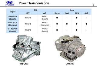
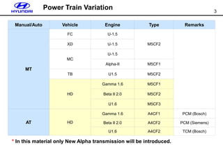
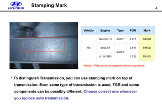
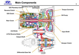
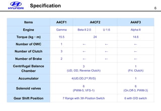
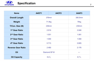
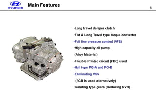
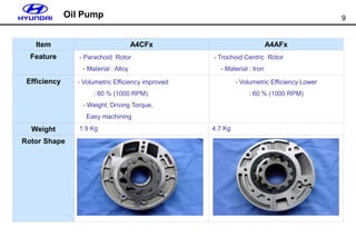
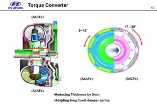
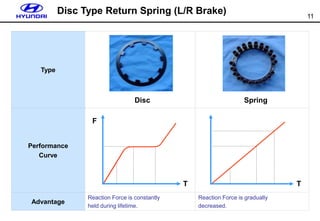
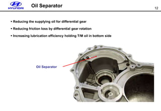
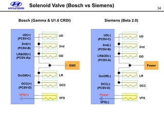
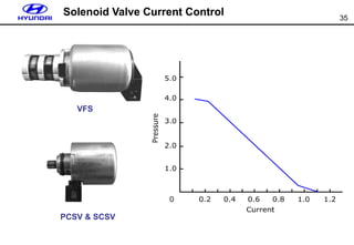
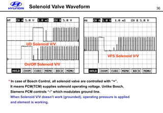
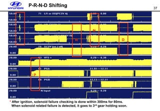
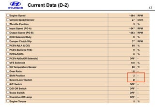
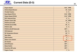
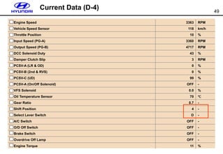
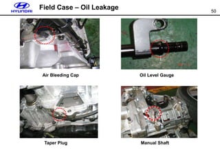
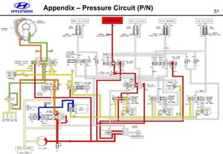
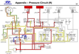
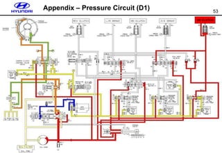
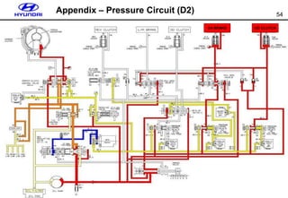
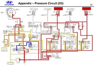
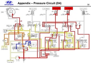
A4CFx – New Alpha
2
Power Train Variation
Engine
T/M Area
M/T A/T Korea NAS GEN AUS
Gamma-1.6
(Bosch)
M5CF1
A4CF1
(Bosch)
● - ● -
Beta II-2.0
(Siemens)
M5CF2
A4CF2
(Siemens)
● ● ● ●
U-1.6(CRDI)
(Bosch)
M5CF3
A4CF2
(Bosch)
● - ● -
(A4CFx)
(M5CFx)
3
Manual/Auto Vehicle Engine Type Remarks
MT
FC U-1.5
M5CF2
XD U-1.5
MC
U-1.5
Alpha-II M5CF1
TB U1.5 M5CF2
HD
Gamma 1.6 M5CF1
Beta II 2.0 M5CF2
U1.6 M5CF3
AT HD
Gamma 1.6 A4CF1 PCM (Bosch)
Beta II 2.0 A4CF2 PCM (Siemens)
U1.6 A4CF2 TCM (Bosch)
* In this material only New Alpha transmission will be introduced.
Power Train Variation
4
Vehicle Engine Type FGR Mark
HD
Gamma 1.6 A4CF1 4.375 A43AD
Beta 2.0
A4CF2
3.849 B48CD
U 1.6 CRDI 3.532 D45JD
* To distinguish Transmission, you can use stamping mark on top of
transmission. Even same type of transmission is used, FGR and some
components can be possibly different. Choose correct one whenever
you replace auto transmission.
Notice : FGR can be changeable without any notice.
Stamping Mark
5
Main Components
Reverse Clutch
O/D Clutch
Rear Cover
2nd Brake
L/R & Reverse Brake
Output Shaft
Differential Gear Set
Damper Clutch
Input Shaft
Oil Pump
Torque Converter
U/D Clutch
Planetary Carrier Gear Set
O/D Planetary Carrier
6
Items A4CF1 A4CF2 A4AF3
Engine Gamma Beta II 2.0 U 1.6 Alpha II
Torque (kgㆍm) 15.5 24 14.6
Number of OWC 1 ← ← ←
Number of Clutch 3 ← ← ←
Number of Brake 2 ← ← ←
Centrifugal Balance
Chamber
3
(UD, OD, Reverse Clutch)
1
(Frt. Clutch)
Accumulator 4(UD,OD,2nd,RVS) 1
Solenoid valves
6
(PWM-5, VFS-1)
6
(On,Off-3, PWM-3)
Gear Shift Position 7 Range with 3th Position Switch 6 with O/D switch
Comparison
Specification
7
Items A4CF1 A4CF2 A4AF3
Overall Length 379mm 390.5mm
Weight 71.9kg 76kg
T/Con. Size (Φ) 236mm 230mm
1st Gear Ratio 2.919 2.846
2nd Gear Ratio 1.551 1.581
3rd Gear Ratio 1.000 1.000
4th Gear Ratio 0.713 0.685
Reverse Gear Ratio 2.480 2.176
Oil Diamond SP III ←
Oil Capacity 6.2 L 6.7 L
Comparison
Specification
8
Main Features
•Long travel damper clutch
•Flat & Long Travel type torque converter
•Full line pressure control (VFS)
•High capacity oil pump
(Alloy Material)
•Flexible Printed circuit (FBC) used
•Hall type PG-A and PG-B
•Eliminating VSS
(PGB is used alternatively)
•Grinding type gears (Reducing NVH)
9
Oil Pump
Item A4CFx A4AFx
Feature - Parachoid Rotor
- Material : Alloy
- Trochoid Centric Rotor
- Material : Iron
Efficiency - Volumetric Efficiency improved
: 80 % (1000 RPM)
- Weight, Driving Torque,
Easy machining
- Volumetric Efficiency Lower
: 60 % (1000 RPM)
Weight 1.9 Kg 4.7 Kg
Rotor Shape
10
Torque Converter
(A4AFx) (A4CFx)
9∼12˚
17 ∼20˚
•Reducing Thickness by 5mm
•Adapting long travel damper spring
(A4CFx)
(A4AFx)
11
Disc Type Return Spring (L/R Brake)
Type
Performance
Curve
Advantage
Reaction Force is constantly
held during lifetime.
Reaction Force is gradually
decreased.
Disc Spring
T
F
T
12
 Reducing the supplying oil for differential gear
 Reducing friction loss by differential gear rotation
 Increasing lubrication efficiency holding T/M oil in bottom side
Oil Separator
Oil Separator
13
Valve Body
•Valve body and spool valve are
from Alloy
• Full line pressure control
• Individual Clutch to Clutch Control
A B
A
C
E
D
A
A
* To remove the valve body,
- A type (6x30mm) : 17EA
- B type (6x35mm) : 1EA
- C type (6x40mm) : 1EA
- D type (6x55mm) : 1EA
- E type (6x60mm) : 1EA
14
PCSV - A : O/D or LR Solenoid
PCSV - B : 2/4 or REV Solenoid
PCSV - C : UD Solenoid
PCSV - D : Damper Clutch Solenoid
On/Off Sol V/V : Switching PCSV – A from LR to O/D
(Switch on – LR engaged, off- O/D engaged)
VFS Solenoid
Solenoid Valve
* Each solenoid can be interchangeable except VFS (Variable Force Solenoid)
15
Accumulator
•Each Spring can be
interchangeable
except white one
ⓑ
ⓒ
ⓓ
ⓐ UD (two springs with white color)
ⓑ OD (one spring with
yellow color)
ⓐ
ⓒ 2nd (two springs with
yellow color)
ⓓ L/R (one spring with
yellow color)
16
Hydraulic Pressure Checking Port
* Totally 8 checking ports are used.
- UD : UD Clutch - RED : Reducing Pressure
- L/R : L/R Brake - O/D : O/D Clutch
- DA : Damper Clutch - 2nd : 2nd Brake
- LUB : Lubrication Pressure - REV : Reverse Clutch
DA
UD L/R
LUB RED O/D 2ND
REV
17
Pressure Circuit (P/N)
L/R BRAKE
18
* Advantage : To improve fuel consumption reducing unnecessary
high pressure so as to decrease fuel consumption rate.
VFS (Variable Force Solenoid)
Comparison Purpose
10.5
4.5
TPS
Gear
1 2 3 4
8.9
6.4
Line pressure (bar)
Pump
Line
pressure Solenoid valve
Pump
Controlled
pressure
Line
pressure
Line pressure (bar)
Regulator valve
Regulator valve
Optimum line
pressure
Improved
efficiency
Lower fuel
consumption
Unnecessary high pressure Optimum pressure
19
VSS (Vehicle Speed Sensor)
•VSS is eliminated in A4CFx. Instead of this, output speed sensor (PGB) is used for
TCM. After filtering from output speed sensor, TCM send its speed information to
cluster visa designated terminal.
In case of engine management, frt. wheel speed sensor is used for vehicle speed
acquisition like MC.
20
Shift Lever & 3rd Gear Position Switch
(A4CFx in HD) (A4AFx in MC)
•In case of MC, it has O/D on or off switch in shift lever. Unlike this, HD has 3 position
sensor instead. When you push shift lever from “D” position to right side “3” position,
shift down to 3rd gear happens from over driving
(4th gear) and turn “3”position lamp in cluster.
21
Shift Lever & 3rd Gear Position Switch
* To disassemble shift lever, first pushing chrome cover down with twisting,
then release the screw.
* “3” gear position switch in installed just bottom side of the shift lever assembly.
It has 3 terminals. One is for D input to TCM, another is for “3” input and the last is
for cluster.
22
Inhibitor Switch
23
FPC (Flexible Printed Circuit) Harness
10P CONN INLINE CONN VFS
PCSV CONN
OTS
10P CONN
INLINE CONN
VFS
PCSV CONN
OTS
* To increase manufacturing efficiency and save
space in solenoid valve, flexible printed circuit
type harness is used.
(Reducing weight by 30%)
(OTS)
(F4CFx) (F4AFx)
24
Items Solenoid Valve(0%:On, 100%:Off)
Range Operation
PCSV-A
(OD&LR)
PCSV-B
(2ND&RVS)
PCSV-C
(UD)
PCSV-D
(DCCSV)
ON/OFF
SOL.
P, N LR OFF ON ON OFF ON
D-1 UD ON ON OFF OFF OFF
D-2 UD, 2ND ON OFF OFF ON OFF
D-3 UD, OD OFF ON OFF ON OFF
D-4 OD, 2ND OFF OFF ON ON OFF
REV LR, RVS OFF OFF ON OFF ON
2 UD, 2ND ON OFF OFF ON OFF
LOW UD, LR OFF ON OFF OFF ON
Operation Chart
25
Input & Output
Input PCM
( TCM )
Battery Power
GND
PG-A & PG-B
OTS
Inhibitor Switch
3rd Gear Position Switch
O/D off Request (Cruise)
Can Communication
VFS
PCSV – A(LR&OD)
PCSV – B(2nd&REV)
PCSV – C(UD)
PCSV – D(DCC)
SCSV – A (On/Off)
2nd & L Input (Cruise)
Cluster Vehicle Speed
Output
26
PCM(TCM) Installation
* Gamma & Beta engine’s case, PCM type TCU controller is used and installed in
engine room compartment.
U1.6 CRDI’s case, ECM and TCM are separated. Unlike ECM which is installed in
engine compartment, TCM is position in passenger
compartment near to in-panel junction box.
Gamma & Beta U 1.6 CRDI
27
Pin Connection with Gamma Engine
Pin Description Pin Description
1 GND (PCM) 68 Inhibitor L input
3 GND (Solenoid) 70 GND (VFS)
4 Voltage Supply for TCM 71 PCSV-A(LR & O/D)
5 Voltage Supply for TCM 72 PCSV-B (2nd & RVS)
26 On/Off Solenoid 80 GND (OTS)
27 PCSV-D (DCC) 82 GND (PG-B)
47 2 & L Position to Cruise 83 GND (PG-A)
48 Gear Information (Duty) to Cluster 86 Input Brake Switch (TCM)
49 Output Vehicle Speed to Cluster 88 Inhibitor R Input
57 OTS (Oil Temperature Sensor) 89 Inhibitor 2nd Input
60 Output Speed Sensor (PGB) 90 Inhibitor 3rd Input
61 Input Speed Sensor (PGA) 91 Inhibitor N Input
65 O/D off Request form Cruise 92 GND (TCM)
66 Inhibitor D input 93 VFS Control
67 Inhibitor P input 94 PCSV-C (UD)
28
Pin Connection with Beta Engine
Pin Description Pin Description
1 Power Supply (TCM) 20 GND (TCM)
2 Power Supply (TCM) 34 GND (TCM)
4 Power Supply (VFS) 35 GND (TCM)
6 Inhibitor P Input 38 Brake Switch
7 Inhibitor R Input 39 O/D Off Request from Cruise
8 Inhibitor N Input 46 PCSV-A (LR & O/D “-” Control)
9 Inhibitor D Input 48 PCSV-C (UD “-” Control)
10 Inhibitor 3 Input 49 Power Supply (Solenoid)
11 Inhibitor 2 Input 50 Power Supply (Solenoid)
12 Inhibitor L input 52 2 or L Gear Information to Cruise
14 Auto Cruise On/Off Input 53 Vehicle Speed Output to Cluster
15 GND (PG-A) 54 OTS (Oil Temperature Sensor)
16 On/Off Solenoid (“-” Control) 55 GND (OTS)
17 PCSV-B(2nd & RVS “–” Control) 56 Output Speed Sensor (PG-B)
18 PCSV-D(DCC “–” Control) 57 GND (PGB)
19 VFS ( “-” Control) 58 Input Speed Sensor (PG-A)
29
Pin Connection with U 1.6 CRDI
Pin Description Pin Description
1 Power Supply (TCM) 23 Inhibitor R Input
2 Power Supply (TCM) 24 Inhibitor P input
3 GND (TCM) 35 Shield for CAN
4 GND (TCM) 36 CAN High
5 GND (Solenoid Valve) 37 CAN Low
6 PCSV-A (LR & O/D) 38 K Line
7 PCSV-B (2nd & RVS) 42 O/D Off Request from Cruise
8 PCSV-C (UD) 44 GND (VFS)
9 PCSV-D (DCC) 51 2 or L Gear Information to Cruise
10 On/Off Solenoid Valve 53 Vehicle Speed Out to Cluster
12 Power Supply (TCM) 58 OTS (Oil Temperature Sensor)
14 VFS Control (+) 59 GND (PG-B)
17 Brake Switch Input (TCM) 61 Output Speed Sensor (PG-B)
18 Inhibitor L Input 62 Input Speed Sensor (PG-A)
19 Inhibitor 2 Input 74 GND (OTS)
20 Inhibitor 3 Input 78 GND (PG-A)
21 Inhibitor D Input 80 Shield for PG-B
22 Inhibitor N input 81 Shield for PG-A
30
Input (PG-A) and Output Speed Sensor (PG-B)
Input speed sensor is signaled from
O/D clutch retainer. This is alternatively
used for VSS information when output
speed sensor has any failure.
Output speed sensor is captured from
transfer driven gear. Both input and
output speed sensor are from hall IC
type which signals with digital wave.
When both sensors have failures, cluster
speedometer doesn’t work since main
input for this is from these sensors (Main is output
speed sensor)
31
PG-A & PG-B Waveform
PG-A
PG-B
•PB-A & PG-B are from hall IC type. Checking methods are the same with Hivec’s.
You can check with current data or measure the waveform from the sensors.
After receiving signal information, TCM sends VSS to cluster.
VSS (From PCM to Cluster)
32
PG-A & PG-B Failure
* When PG-A or PG-B failure is detected, electrically gear shifting is held
in 3rd range but possibly 3rd to 2nd shifting is allowed.
A to B : 1.08s
Failure Detected
33
OTS (Oil Temperature Sensor)
* When OTS failure is detected, OTS current data sets to 80℃.
34
GND
Solenoid Valve (Bosch vs Siemens)
UD
2nd
OD
LR
DCC
VFS
UD(-)
(PCSV-C)
2nd(-)
(PCSV-B)
LR&OD(-)
(PCSV-A)
On/Off(-)
DCC(-)
(PCSV-D)
Power
Siemens (Beta 2.0)
VFS(-)
Bosch (Gamma & U1.6 CRDI)
UD
2nd
OD
LR
DCC
VFS
UD(+)
(PCSV-C)
2nd(+)
(PCSV-B)
LR&OD(+)
(PCSV-A)z
On/Off(+)
DCC(+)
(PCSV-D)
VFS(+)
Power
35
Solenoid Valve Current Control
VFS
PCSV & SCSV
36
UD Solenoid V/V
On/Off Solenoid V/V
VFS Solenoid V/V
Solenoid Valve Waveform
* In case of Bosch Control, all solenoid valve are controlled with “+”.
It means PCM(TCM) supplies solenoid operating voltage. Unlike Bosch,
Siemens PCM controls “-” which modulates ground line.
When Solenoid V/V doesn’t work (grounded), operating pressure is applied
and element is working.
37
P-R-N-D Shifting
P
R
N
D
* After ignition, solenoid failure checking is done within 300ms for 80ms.
When solenoid related failure is detected, it goes to 3rd gear holding soon.
38
Solenoid Valve Fail (3rd Gear Fixed)
A to B : 1.8s
* SCSV solenoid valve shorts to ground during driving under 3rd gear
resulting in mechanical 3rd gear fixed condition.
39
3rd Position Input (O/D Off)
* In stead of O/D off switch in MC (A4AFx), HD utilizes 3rd position. When
this signal inputs to PCM(TCM), shift down is down from 4th to 3rd.
Driving with 4th
3rd Input
Shift Down to 3rd
40
Stall Test
L 2 3 R
41
Resetting Auto T/A Values
42
TCM
CAN Bus CAN_Low
CAN_High
CAN_L
CAN_H
Resistance
In J/Box
(120 Ω)
ECM
(120 Ω)
Can Communication
* Between ECM and TCM especially in U 1.6 liter outside CAN communication
is used. (Gamma and Beta II : Internal CAN)
When CAN system error happens, following values go to fail safe like
- Engine rpm : 3000
- Engine Torque : 63%
- A/Con. S/W : Off
- Throttle Position : 50%
43
CAN Data in Failure
44
Engine Speed 651 RPM
Vehicle Speed Sensor O km/h
Throttle Position 0 %
Input Speed (PG-A) 627 RPM
Output Speed (PG-B) 0 RPM
DCC Solenoid Duty 0 %
Damper Clutch Slip 24 RPM
PCSV-A (LR & OD) 0 %
PCSV-B (2nd & RVS) 99 %
PCSV-C (UD) 99 %
PCSV-A (On/Off Solenoid) ON -
VFS Solenoid 0.0 %
Oil Temperature Sensor 73 ℃
Gear Ratio 0.0 -
Shift Position R,N,R -
Select Lever Switch P,N -
A/C Switch OFF -
O/D Off Switch OFF -
Brake Switch OFF -
Overdrive Off Lamp OFF -
Engine Torque 0 %
Current Data (P&N)
45
Engine Speed 706 RPM
Vehicle Speed Sensor 2 km/h
Throttle Position 0 %
Input Speed (PG-A) 620 RPM
Output Speed (PG-B) 249 RPM
DCC Solenoid Duty 0 %
Damper Clutch Slip 86 RPM
PCSV-A(LR & OD) 0 %
PCSV-B(2nd & RVS) 0 %
PCSV-C (UD) 99 %
PCSV-A (On/Off Solenoid) ON -
VFS Solenoid 0.0 %
Oil Temperature Sensor 70 ℃
Gear Ratio 2.5 -
Shift Position R,N,R -
Select Lever Switch R -
A/C Switch OFF -
O/D Off Switch OFF -
Brake Switch OFF -
Overdrive Off Lamp OFF -
Engine Torque 2 %
Current Data (R)
46
Engine Speed 718 RPM
Vehicle Speed Sensor 5 km/h
Throttle Position 0 %
Input Speed (PG-A) 654 RPM
Output Speed (PG-B) 241 RPM
DCC Solenoid Duty 0 %
Damper Clutch Slip 64 RPM
PCSV-A (LR & OD) 99 %
PCSV-B (2nd & RVS) 99 %
PCSV-C (UD) 0 %
PCSV-A (On/Off Solenoid) OFF -
VFS Solenoid 0.0 %
Oil Temperature Sensor 70 ℃
Gear Ratio 2.9 -
Shift Position 1 -
Select Lever Switch D -
A/C Switch OFF -
O/D Off Switch OFF -
Brake Switch OFF -
Overdrive Off Lamp OFF -
Engine Torque 1 %
Current Data (D-1)
47
Engine Speed 1684 RPM
Vehicle Speed Sensor 27 km/h
Throttle Position 3 %
Input Speed (PG-A) 1647 RPM
Output Speed (PG-B) 1063 RPM
DCC Solenoid Duty 0 %
Damper Clutch Slip 37 RPM
PCSV-A(LR & OD) 99 %
PCSV-B(2nd & RVS) 0 %
PCSV-C(UD) 0 %
PCSV-A(On/Off Solenoid) OFF -
VFS Solenoid 0.0 %
Oil Temperature Sensor 80 ℃
Gear Ratio 1.6 -
Shift Position 2 -
Select Lever Switch D -
A/C Switch OFF -
O/D Off Switch OFF -
Brake Switch OFF -
Overdrive Off Lamp OFF -
Engine Torque 5 %
Current Data (D-2)
48
Engine Speed 1343 RPM
Vehicle Speed Sensor 30 km/h
Throttle Position 3 %
Input Speed (PG-A) 1319 RPM
Output Speed (PG-B) 1319 RPM
DCC Solenoid Duty 0 %
Damper Clutch Slip 24 RPM
PCSV-A (LR & OD) 0 %
PCSV-B (2nd & RVS) 99 %
PCSV-C (UD) 0 %
PCSV-A (On/Off Solenoid) OFF -
VFS Solenoid 0.0 %
Oil Temperature Sensor 80 ℃
Gear Ratio 1.0 -
Shift Position 3 -
Select Lever Switch D -
A/C Switch OFF -
O/D Off Switch OFF -
Brake Switch OFF -
Overdrive Off Lamp OFF -
Engine Torque 7 %
Current Data (D-3)
49
Engine Speed 3363 RPM
Vehicle Speed Sensor 118 km/h
Throttle Position 10 %
Input Speed (PG-A) 3360 RPM
Output Speed (PG-B) 4717 RPM
DCC Solenoid Duty 43 %
Damper Clutch Slip 3 RPM
PCSV-A (LR & OD) 0 %
PCSV-B (2nd & RVS) 0 %
PCSV-C (UD) 99 %
PCSV-A (On/Off Solenoid) OFF -
VFS Solenoid 0.0 %
Oil Temperature Sensor 70 ℃
Gear Ratio 0.7 -
Shift Position 4 -
Select Lever Switch D -
A/C Switch OFF -
O/D Off Switch OFF -
Brake Switch OFF -
Overdrive Off Lamp OFF -
Engine Torque 11 %
Current Data (D-4)
50
Field Case – Oil Leakage
Air Bleeding Cap Oil Level Gauge
Taper Plug Manual Shaft
51
Appendix – Pressure Circuit (P/N)
L/R BRAKE
52
Appendix – Pressure Circuit (R)
L/R BRAKE
REV CLUTCH
53
Appendix – Pressure Circuit (D1)
UD CLUTCH
54
Appendix – Pressure Circuit (D2)
UD CLUTCH
2/4 BRAKE
55
Appendix – Pressure Circuit (D3)
UD CLUTCH
OD CLUTCH
56
Appendix – Pressure Circuit (D4)
OD CLUTCH 2/4 BRAKE

Transaxle system hyundai training new alpha

  • 1.
  • 2.
    2 Power Train Variation Engine T/MArea M/T A/T Korea NAS GEN AUS Gamma-1.6 (Bosch) M5CF1 A4CF1 (Bosch) ● - ● - Beta II-2.0 (Siemens) M5CF2 A4CF2 (Siemens) ● ● ● ● U-1.6(CRDI) (Bosch) M5CF3 A4CF2 (Bosch) ● - ● - (A4CFx) (M5CFx)
  • 3.
    3 Manual/Auto Vehicle EngineType Remarks MT FC U-1.5 M5CF2 XD U-1.5 MC U-1.5 Alpha-II M5CF1 TB U1.5 M5CF2 HD Gamma 1.6 M5CF1 Beta II 2.0 M5CF2 U1.6 M5CF3 AT HD Gamma 1.6 A4CF1 PCM (Bosch) Beta II 2.0 A4CF2 PCM (Siemens) U1.6 A4CF2 TCM (Bosch) * In this material only New Alpha transmission will be introduced. Power Train Variation
  • 4.
    4 Vehicle Engine TypeFGR Mark HD Gamma 1.6 A4CF1 4.375 A43AD Beta 2.0 A4CF2 3.849 B48CD U 1.6 CRDI 3.532 D45JD * To distinguish Transmission, you can use stamping mark on top of transmission. Even same type of transmission is used, FGR and some components can be possibly different. Choose correct one whenever you replace auto transmission. Notice : FGR can be changeable without any notice. Stamping Mark
  • 5.
    5 Main Components Reverse Clutch O/DClutch Rear Cover 2nd Brake L/R & Reverse Brake Output Shaft Differential Gear Set Damper Clutch Input Shaft Oil Pump Torque Converter U/D Clutch Planetary Carrier Gear Set O/D Planetary Carrier
  • 6.
    6 Items A4CF1 A4CF2A4AF3 Engine Gamma Beta II 2.0 U 1.6 Alpha II Torque (kgㆍm) 15.5 24 14.6 Number of OWC 1 ← ← ← Number of Clutch 3 ← ← ← Number of Brake 2 ← ← ← Centrifugal Balance Chamber 3 (UD, OD, Reverse Clutch) 1 (Frt. Clutch) Accumulator 4(UD,OD,2nd,RVS) 1 Solenoid valves 6 (PWM-5, VFS-1) 6 (On,Off-3, PWM-3) Gear Shift Position 7 Range with 3th Position Switch 6 with O/D switch Comparison Specification
  • 7.
    7 Items A4CF1 A4CF2A4AF3 Overall Length 379mm 390.5mm Weight 71.9kg 76kg T/Con. Size (Φ) 236mm 230mm 1st Gear Ratio 2.919 2.846 2nd Gear Ratio 1.551 1.581 3rd Gear Ratio 1.000 1.000 4th Gear Ratio 0.713 0.685 Reverse Gear Ratio 2.480 2.176 Oil Diamond SP III ← Oil Capacity 6.2 L 6.7 L Comparison Specification
  • 8.
    8 Main Features •Long traveldamper clutch •Flat & Long Travel type torque converter •Full line pressure control (VFS) •High capacity oil pump (Alloy Material) •Flexible Printed circuit (FBC) used •Hall type PG-A and PG-B •Eliminating VSS (PGB is used alternatively) •Grinding type gears (Reducing NVH)
  • 9.
    9 Oil Pump Item A4CFxA4AFx Feature - Parachoid Rotor - Material : Alloy - Trochoid Centric Rotor - Material : Iron Efficiency - Volumetric Efficiency improved : 80 % (1000 RPM) - Weight, Driving Torque, Easy machining - Volumetric Efficiency Lower : 60 % (1000 RPM) Weight 1.9 Kg 4.7 Kg Rotor Shape
  • 10.
    10 Torque Converter (A4AFx) (A4CFx) 9∼12˚ 17∼20˚ •Reducing Thickness by 5mm •Adapting long travel damper spring (A4CFx) (A4AFx)
  • 11.
    11 Disc Type ReturnSpring (L/R Brake) Type Performance Curve Advantage Reaction Force is constantly held during lifetime. Reaction Force is gradually decreased. Disc Spring T F T
  • 12.
    12  Reducing thesupplying oil for differential gear  Reducing friction loss by differential gear rotation  Increasing lubrication efficiency holding T/M oil in bottom side Oil Separator Oil Separator
  • 13.
    13 Valve Body •Valve bodyand spool valve are from Alloy • Full line pressure control • Individual Clutch to Clutch Control A B A C E D A A * To remove the valve body, - A type (6x30mm) : 17EA - B type (6x35mm) : 1EA - C type (6x40mm) : 1EA - D type (6x55mm) : 1EA - E type (6x60mm) : 1EA
  • 14.
    14 PCSV - A: O/D or LR Solenoid PCSV - B : 2/4 or REV Solenoid PCSV - C : UD Solenoid PCSV - D : Damper Clutch Solenoid On/Off Sol V/V : Switching PCSV – A from LR to O/D (Switch on – LR engaged, off- O/D engaged) VFS Solenoid Solenoid Valve * Each solenoid can be interchangeable except VFS (Variable Force Solenoid)
  • 15.
    15 Accumulator •Each Spring canbe interchangeable except white one ⓑ ⓒ ⓓ ⓐ UD (two springs with white color) ⓑ OD (one spring with yellow color) ⓐ ⓒ 2nd (two springs with yellow color) ⓓ L/R (one spring with yellow color)
  • 16.
    16 Hydraulic Pressure CheckingPort * Totally 8 checking ports are used. - UD : UD Clutch - RED : Reducing Pressure - L/R : L/R Brake - O/D : O/D Clutch - DA : Damper Clutch - 2nd : 2nd Brake - LUB : Lubrication Pressure - REV : Reverse Clutch DA UD L/R LUB RED O/D 2ND REV
  • 17.
  • 18.
    18 * Advantage :To improve fuel consumption reducing unnecessary high pressure so as to decrease fuel consumption rate. VFS (Variable Force Solenoid) Comparison Purpose 10.5 4.5 TPS Gear 1 2 3 4 8.9 6.4 Line pressure (bar) Pump Line pressure Solenoid valve Pump Controlled pressure Line pressure Line pressure (bar) Regulator valve Regulator valve Optimum line pressure Improved efficiency Lower fuel consumption Unnecessary high pressure Optimum pressure
  • 19.
    19 VSS (Vehicle SpeedSensor) •VSS is eliminated in A4CFx. Instead of this, output speed sensor (PGB) is used for TCM. After filtering from output speed sensor, TCM send its speed information to cluster visa designated terminal. In case of engine management, frt. wheel speed sensor is used for vehicle speed acquisition like MC.
  • 20.
    20 Shift Lever &3rd Gear Position Switch (A4CFx in HD) (A4AFx in MC) •In case of MC, it has O/D on or off switch in shift lever. Unlike this, HD has 3 position sensor instead. When you push shift lever from “D” position to right side “3” position, shift down to 3rd gear happens from over driving (4th gear) and turn “3”position lamp in cluster.
  • 21.
    21 Shift Lever &3rd Gear Position Switch * To disassemble shift lever, first pushing chrome cover down with twisting, then release the screw. * “3” gear position switch in installed just bottom side of the shift lever assembly. It has 3 terminals. One is for D input to TCM, another is for “3” input and the last is for cluster.
  • 22.
  • 23.
    23 FPC (Flexible PrintedCircuit) Harness 10P CONN INLINE CONN VFS PCSV CONN OTS 10P CONN INLINE CONN VFS PCSV CONN OTS * To increase manufacturing efficiency and save space in solenoid valve, flexible printed circuit type harness is used. (Reducing weight by 30%) (OTS) (F4CFx) (F4AFx)
  • 24.
    24 Items Solenoid Valve(0%:On,100%:Off) Range Operation PCSV-A (OD&LR) PCSV-B (2ND&RVS) PCSV-C (UD) PCSV-D (DCCSV) ON/OFF SOL. P, N LR OFF ON ON OFF ON D-1 UD ON ON OFF OFF OFF D-2 UD, 2ND ON OFF OFF ON OFF D-3 UD, OD OFF ON OFF ON OFF D-4 OD, 2ND OFF OFF ON ON OFF REV LR, RVS OFF OFF ON OFF ON 2 UD, 2ND ON OFF OFF ON OFF LOW UD, LR OFF ON OFF OFF ON Operation Chart
  • 25.
    25 Input & Output InputPCM ( TCM ) Battery Power GND PG-A & PG-B OTS Inhibitor Switch 3rd Gear Position Switch O/D off Request (Cruise) Can Communication VFS PCSV – A(LR&OD) PCSV – B(2nd&REV) PCSV – C(UD) PCSV – D(DCC) SCSV – A (On/Off) 2nd & L Input (Cruise) Cluster Vehicle Speed Output
  • 26.
    26 PCM(TCM) Installation * Gamma& Beta engine’s case, PCM type TCU controller is used and installed in engine room compartment. U1.6 CRDI’s case, ECM and TCM are separated. Unlike ECM which is installed in engine compartment, TCM is position in passenger compartment near to in-panel junction box. Gamma & Beta U 1.6 CRDI
  • 27.
    27 Pin Connection withGamma Engine Pin Description Pin Description 1 GND (PCM) 68 Inhibitor L input 3 GND (Solenoid) 70 GND (VFS) 4 Voltage Supply for TCM 71 PCSV-A(LR & O/D) 5 Voltage Supply for TCM 72 PCSV-B (2nd & RVS) 26 On/Off Solenoid 80 GND (OTS) 27 PCSV-D (DCC) 82 GND (PG-B) 47 2 & L Position to Cruise 83 GND (PG-A) 48 Gear Information (Duty) to Cluster 86 Input Brake Switch (TCM) 49 Output Vehicle Speed to Cluster 88 Inhibitor R Input 57 OTS (Oil Temperature Sensor) 89 Inhibitor 2nd Input 60 Output Speed Sensor (PGB) 90 Inhibitor 3rd Input 61 Input Speed Sensor (PGA) 91 Inhibitor N Input 65 O/D off Request form Cruise 92 GND (TCM) 66 Inhibitor D input 93 VFS Control 67 Inhibitor P input 94 PCSV-C (UD)
  • 28.
    28 Pin Connection withBeta Engine Pin Description Pin Description 1 Power Supply (TCM) 20 GND (TCM) 2 Power Supply (TCM) 34 GND (TCM) 4 Power Supply (VFS) 35 GND (TCM) 6 Inhibitor P Input 38 Brake Switch 7 Inhibitor R Input 39 O/D Off Request from Cruise 8 Inhibitor N Input 46 PCSV-A (LR & O/D “-” Control) 9 Inhibitor D Input 48 PCSV-C (UD “-” Control) 10 Inhibitor 3 Input 49 Power Supply (Solenoid) 11 Inhibitor 2 Input 50 Power Supply (Solenoid) 12 Inhibitor L input 52 2 or L Gear Information to Cruise 14 Auto Cruise On/Off Input 53 Vehicle Speed Output to Cluster 15 GND (PG-A) 54 OTS (Oil Temperature Sensor) 16 On/Off Solenoid (“-” Control) 55 GND (OTS) 17 PCSV-B(2nd & RVS “–” Control) 56 Output Speed Sensor (PG-B) 18 PCSV-D(DCC “–” Control) 57 GND (PGB) 19 VFS ( “-” Control) 58 Input Speed Sensor (PG-A)
  • 29.
    29 Pin Connection withU 1.6 CRDI Pin Description Pin Description 1 Power Supply (TCM) 23 Inhibitor R Input 2 Power Supply (TCM) 24 Inhibitor P input 3 GND (TCM) 35 Shield for CAN 4 GND (TCM) 36 CAN High 5 GND (Solenoid Valve) 37 CAN Low 6 PCSV-A (LR & O/D) 38 K Line 7 PCSV-B (2nd & RVS) 42 O/D Off Request from Cruise 8 PCSV-C (UD) 44 GND (VFS) 9 PCSV-D (DCC) 51 2 or L Gear Information to Cruise 10 On/Off Solenoid Valve 53 Vehicle Speed Out to Cluster 12 Power Supply (TCM) 58 OTS (Oil Temperature Sensor) 14 VFS Control (+) 59 GND (PG-B) 17 Brake Switch Input (TCM) 61 Output Speed Sensor (PG-B) 18 Inhibitor L Input 62 Input Speed Sensor (PG-A) 19 Inhibitor 2 Input 74 GND (OTS) 20 Inhibitor 3 Input 78 GND (PG-A) 21 Inhibitor D Input 80 Shield for PG-B 22 Inhibitor N input 81 Shield for PG-A
  • 30.
    30 Input (PG-A) andOutput Speed Sensor (PG-B) Input speed sensor is signaled from O/D clutch retainer. This is alternatively used for VSS information when output speed sensor has any failure. Output speed sensor is captured from transfer driven gear. Both input and output speed sensor are from hall IC type which signals with digital wave. When both sensors have failures, cluster speedometer doesn’t work since main input for this is from these sensors (Main is output speed sensor)
  • 31.
    31 PG-A & PG-BWaveform PG-A PG-B •PB-A & PG-B are from hall IC type. Checking methods are the same with Hivec’s. You can check with current data or measure the waveform from the sensors. After receiving signal information, TCM sends VSS to cluster. VSS (From PCM to Cluster)
  • 32.
    32 PG-A & PG-BFailure * When PG-A or PG-B failure is detected, electrically gear shifting is held in 3rd range but possibly 3rd to 2nd shifting is allowed. A to B : 1.08s Failure Detected
  • 33.
    33 OTS (Oil TemperatureSensor) * When OTS failure is detected, OTS current data sets to 80℃.
  • 34.
    34 GND Solenoid Valve (Boschvs Siemens) UD 2nd OD LR DCC VFS UD(-) (PCSV-C) 2nd(-) (PCSV-B) LR&OD(-) (PCSV-A) On/Off(-) DCC(-) (PCSV-D) Power Siemens (Beta 2.0) VFS(-) Bosch (Gamma & U1.6 CRDI) UD 2nd OD LR DCC VFS UD(+) (PCSV-C) 2nd(+) (PCSV-B) LR&OD(+) (PCSV-A)z On/Off(+) DCC(+) (PCSV-D) VFS(+) Power
  • 35.
    35 Solenoid Valve CurrentControl VFS PCSV & SCSV
  • 36.
    36 UD Solenoid V/V On/OffSolenoid V/V VFS Solenoid V/V Solenoid Valve Waveform * In case of Bosch Control, all solenoid valve are controlled with “+”. It means PCM(TCM) supplies solenoid operating voltage. Unlike Bosch, Siemens PCM controls “-” which modulates ground line. When Solenoid V/V doesn’t work (grounded), operating pressure is applied and element is working.
  • 37.
    37 P-R-N-D Shifting P R N D * Afterignition, solenoid failure checking is done within 300ms for 80ms. When solenoid related failure is detected, it goes to 3rd gear holding soon.
  • 38.
    38 Solenoid Valve Fail(3rd Gear Fixed) A to B : 1.8s * SCSV solenoid valve shorts to ground during driving under 3rd gear resulting in mechanical 3rd gear fixed condition.
  • 39.
    39 3rd Position Input(O/D Off) * In stead of O/D off switch in MC (A4AFx), HD utilizes 3rd position. When this signal inputs to PCM(TCM), shift down is down from 4th to 3rd. Driving with 4th 3rd Input Shift Down to 3rd
  • 40.
  • 41.
  • 42.
    42 TCM CAN Bus CAN_Low CAN_High CAN_L CAN_H Resistance InJ/Box (120 Ω) ECM (120 Ω) Can Communication * Between ECM and TCM especially in U 1.6 liter outside CAN communication is used. (Gamma and Beta II : Internal CAN) When CAN system error happens, following values go to fail safe like - Engine rpm : 3000 - Engine Torque : 63% - A/Con. S/W : Off - Throttle Position : 50%
  • 43.
  • 44.
    44 Engine Speed 651RPM Vehicle Speed Sensor O km/h Throttle Position 0 % Input Speed (PG-A) 627 RPM Output Speed (PG-B) 0 RPM DCC Solenoid Duty 0 % Damper Clutch Slip 24 RPM PCSV-A (LR & OD) 0 % PCSV-B (2nd & RVS) 99 % PCSV-C (UD) 99 % PCSV-A (On/Off Solenoid) ON - VFS Solenoid 0.0 % Oil Temperature Sensor 73 ℃ Gear Ratio 0.0 - Shift Position R,N,R - Select Lever Switch P,N - A/C Switch OFF - O/D Off Switch OFF - Brake Switch OFF - Overdrive Off Lamp OFF - Engine Torque 0 % Current Data (P&N)
  • 45.
    45 Engine Speed 706RPM Vehicle Speed Sensor 2 km/h Throttle Position 0 % Input Speed (PG-A) 620 RPM Output Speed (PG-B) 249 RPM DCC Solenoid Duty 0 % Damper Clutch Slip 86 RPM PCSV-A(LR & OD) 0 % PCSV-B(2nd & RVS) 0 % PCSV-C (UD) 99 % PCSV-A (On/Off Solenoid) ON - VFS Solenoid 0.0 % Oil Temperature Sensor 70 ℃ Gear Ratio 2.5 - Shift Position R,N,R - Select Lever Switch R - A/C Switch OFF - O/D Off Switch OFF - Brake Switch OFF - Overdrive Off Lamp OFF - Engine Torque 2 % Current Data (R)
  • 46.
    46 Engine Speed 718RPM Vehicle Speed Sensor 5 km/h Throttle Position 0 % Input Speed (PG-A) 654 RPM Output Speed (PG-B) 241 RPM DCC Solenoid Duty 0 % Damper Clutch Slip 64 RPM PCSV-A (LR & OD) 99 % PCSV-B (2nd & RVS) 99 % PCSV-C (UD) 0 % PCSV-A (On/Off Solenoid) OFF - VFS Solenoid 0.0 % Oil Temperature Sensor 70 ℃ Gear Ratio 2.9 - Shift Position 1 - Select Lever Switch D - A/C Switch OFF - O/D Off Switch OFF - Brake Switch OFF - Overdrive Off Lamp OFF - Engine Torque 1 % Current Data (D-1)
  • 47.
    47 Engine Speed 1684RPM Vehicle Speed Sensor 27 km/h Throttle Position 3 % Input Speed (PG-A) 1647 RPM Output Speed (PG-B) 1063 RPM DCC Solenoid Duty 0 % Damper Clutch Slip 37 RPM PCSV-A(LR & OD) 99 % PCSV-B(2nd & RVS) 0 % PCSV-C(UD) 0 % PCSV-A(On/Off Solenoid) OFF - VFS Solenoid 0.0 % Oil Temperature Sensor 80 ℃ Gear Ratio 1.6 - Shift Position 2 - Select Lever Switch D - A/C Switch OFF - O/D Off Switch OFF - Brake Switch OFF - Overdrive Off Lamp OFF - Engine Torque 5 % Current Data (D-2)
  • 48.
    48 Engine Speed 1343RPM Vehicle Speed Sensor 30 km/h Throttle Position 3 % Input Speed (PG-A) 1319 RPM Output Speed (PG-B) 1319 RPM DCC Solenoid Duty 0 % Damper Clutch Slip 24 RPM PCSV-A (LR & OD) 0 % PCSV-B (2nd & RVS) 99 % PCSV-C (UD) 0 % PCSV-A (On/Off Solenoid) OFF - VFS Solenoid 0.0 % Oil Temperature Sensor 80 ℃ Gear Ratio 1.0 - Shift Position 3 - Select Lever Switch D - A/C Switch OFF - O/D Off Switch OFF - Brake Switch OFF - Overdrive Off Lamp OFF - Engine Torque 7 % Current Data (D-3)
  • 49.
    49 Engine Speed 3363RPM Vehicle Speed Sensor 118 km/h Throttle Position 10 % Input Speed (PG-A) 3360 RPM Output Speed (PG-B) 4717 RPM DCC Solenoid Duty 43 % Damper Clutch Slip 3 RPM PCSV-A (LR & OD) 0 % PCSV-B (2nd & RVS) 0 % PCSV-C (UD) 99 % PCSV-A (On/Off Solenoid) OFF - VFS Solenoid 0.0 % Oil Temperature Sensor 70 ℃ Gear Ratio 0.7 - Shift Position 4 - Select Lever Switch D - A/C Switch OFF - O/D Off Switch OFF - Brake Switch OFF - Overdrive Off Lamp OFF - Engine Torque 11 % Current Data (D-4)
  • 50.
    50 Field Case –Oil Leakage Air Bleeding Cap Oil Level Gauge Taper Plug Manual Shaft
  • 51.
    51 Appendix – PressureCircuit (P/N) L/R BRAKE
  • 52.
    52 Appendix – PressureCircuit (R) L/R BRAKE REV CLUTCH
  • 53.
    53 Appendix – PressureCircuit (D1) UD CLUTCH
  • 54.
    54 Appendix – PressureCircuit (D2) UD CLUTCH 2/4 BRAKE
  • 55.
    55 Appendix – PressureCircuit (D3) UD CLUTCH OD CLUTCH
  • 56.
    56 Appendix – PressureCircuit (D4) OD CLUTCH 2/4 BRAKE