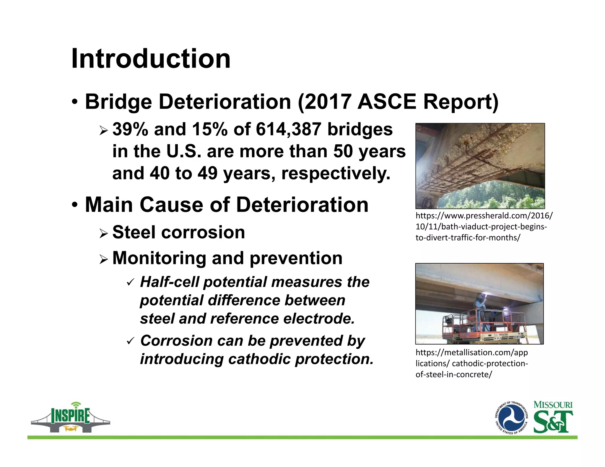
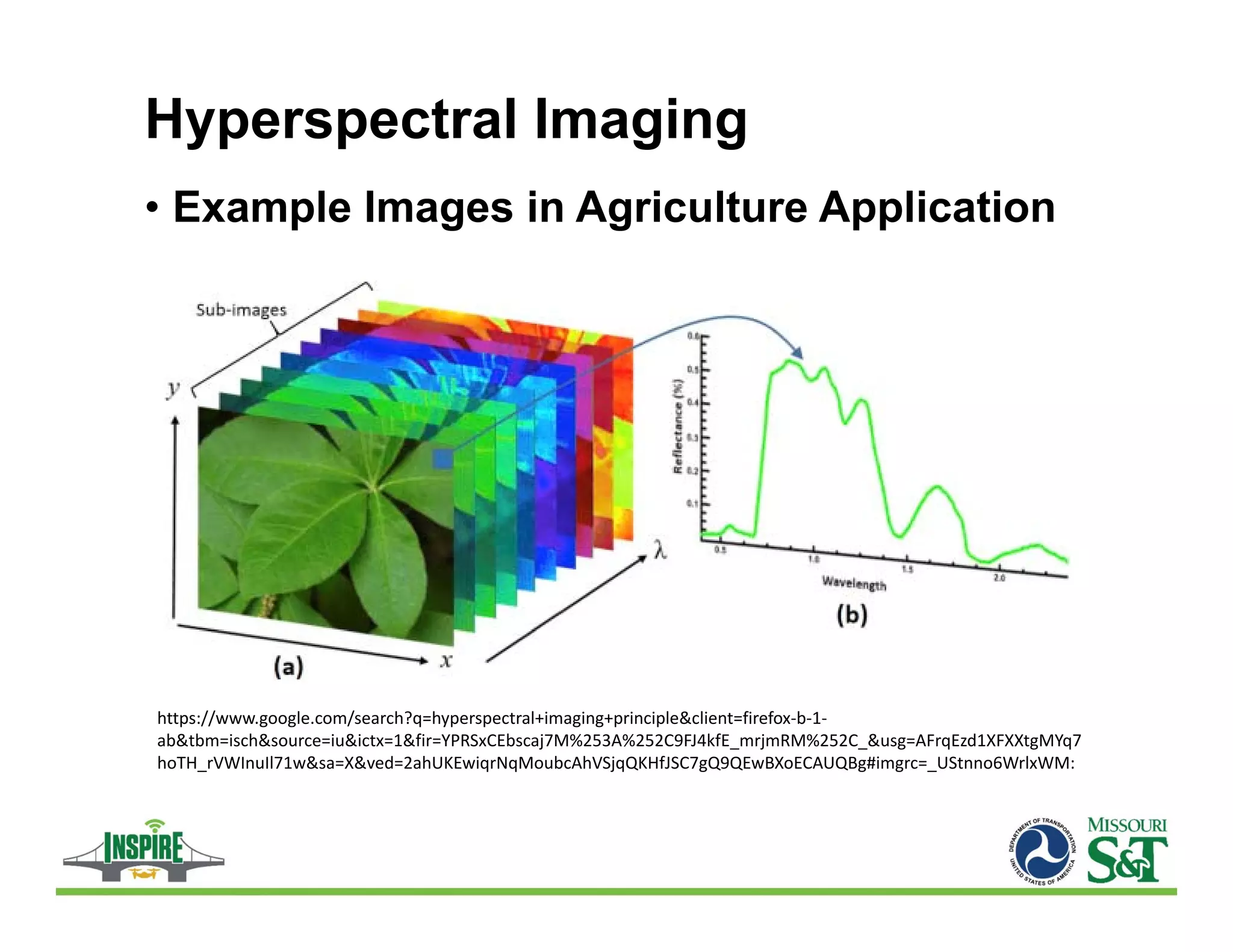
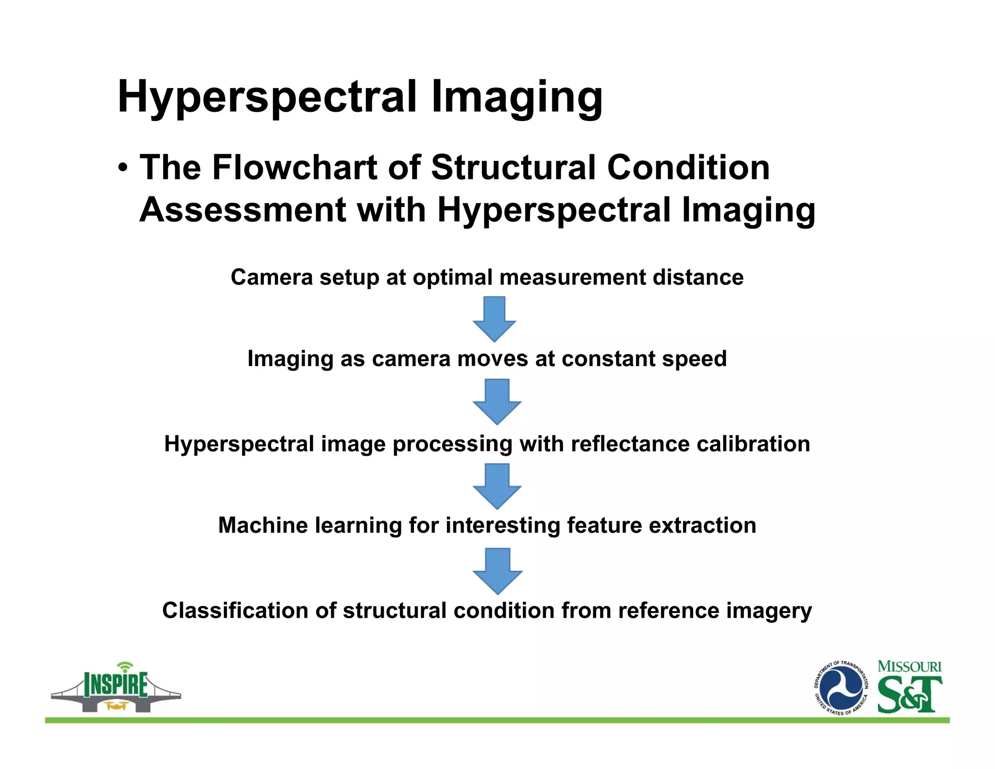
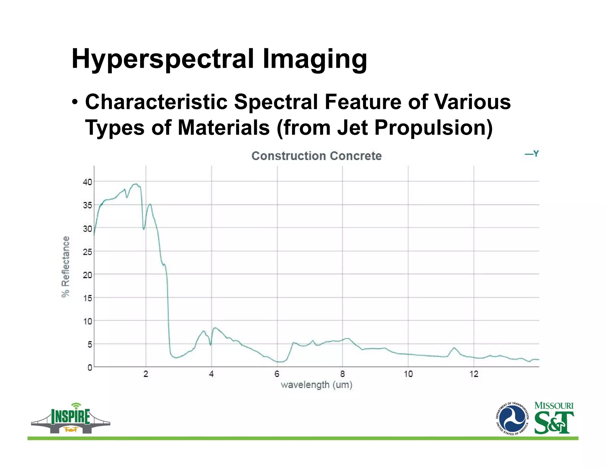
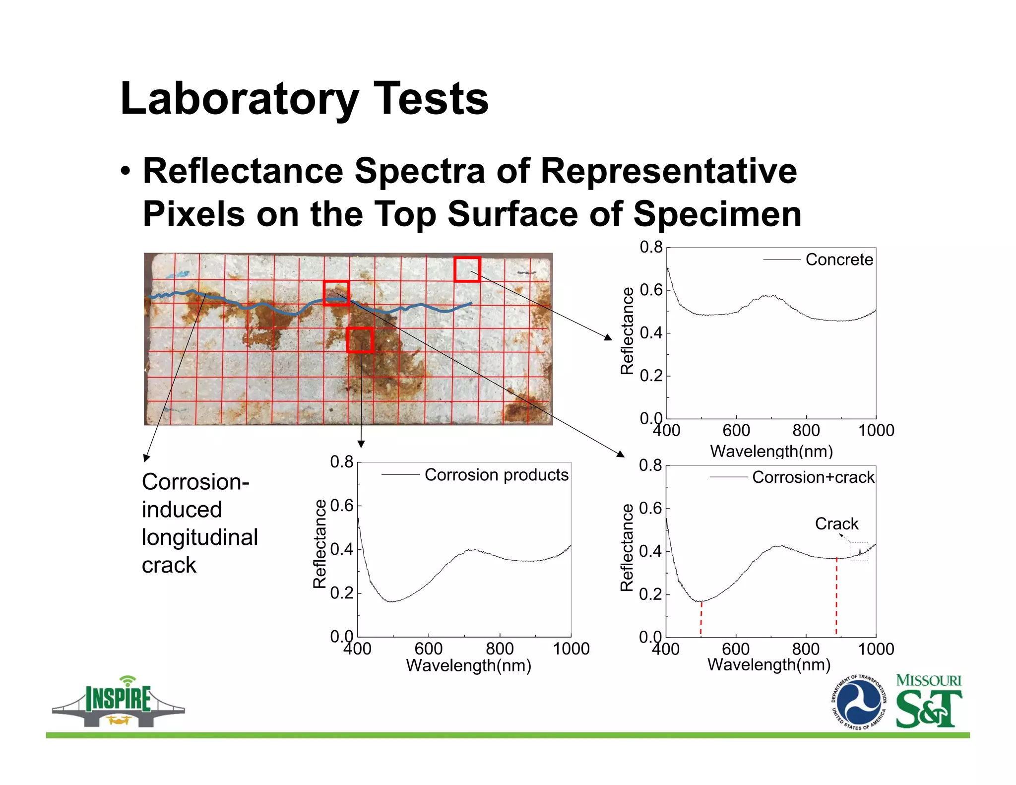
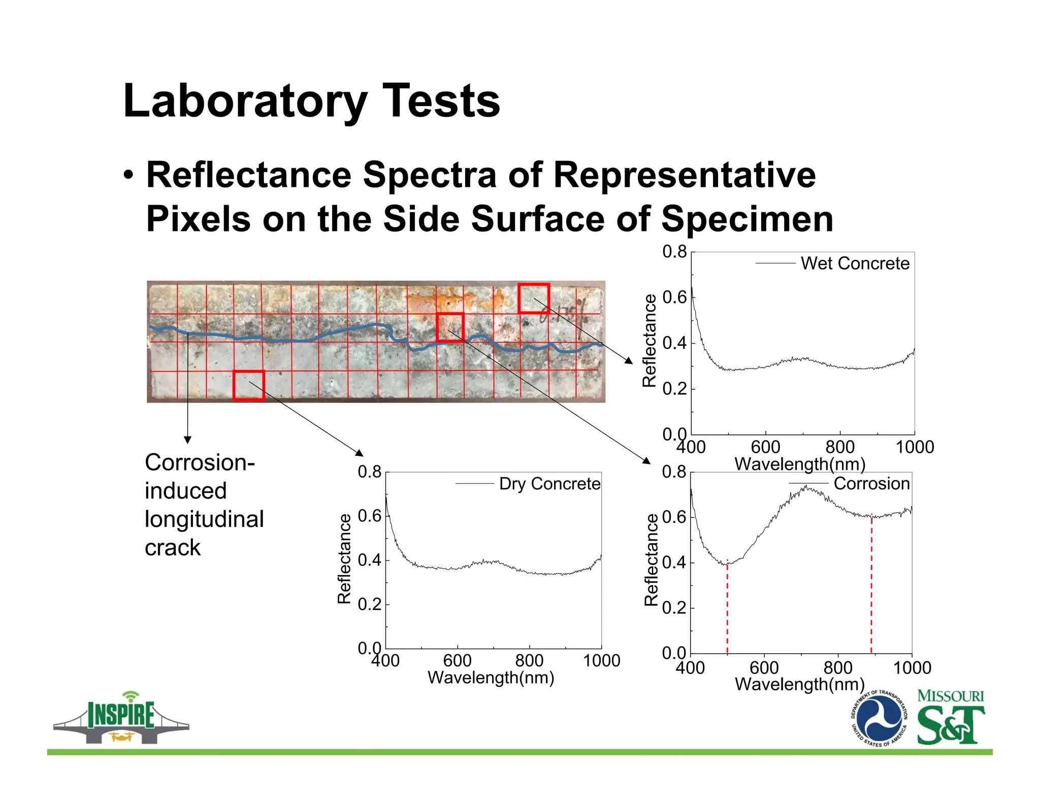
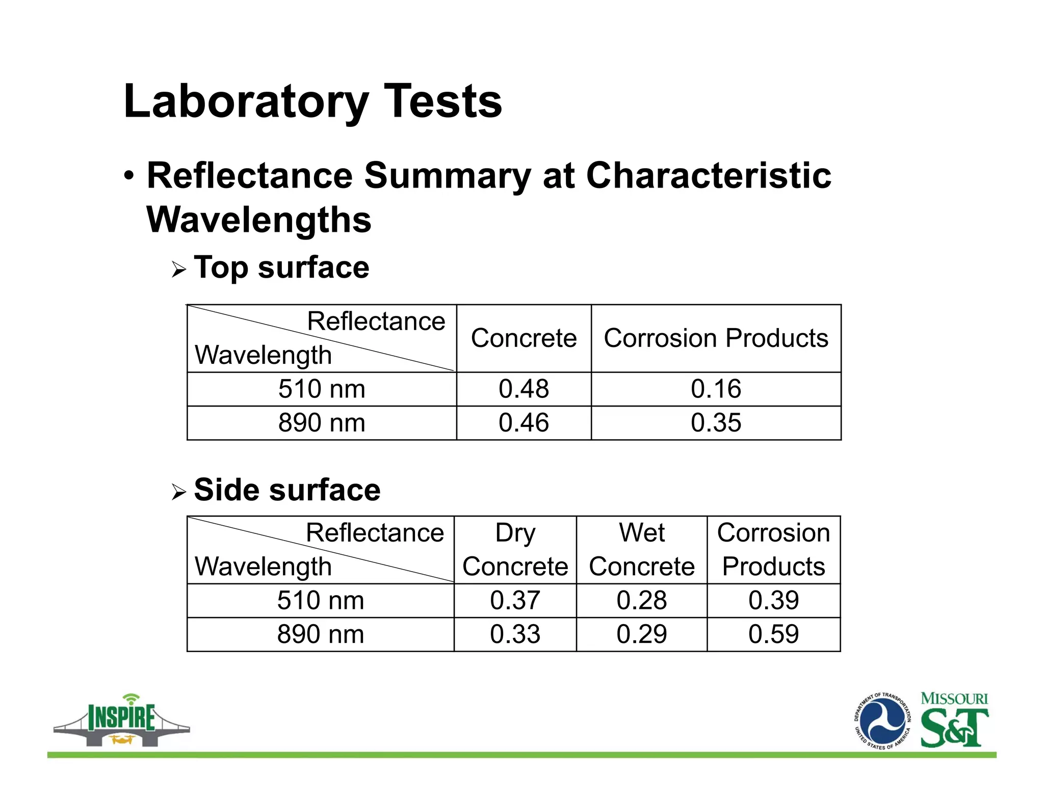
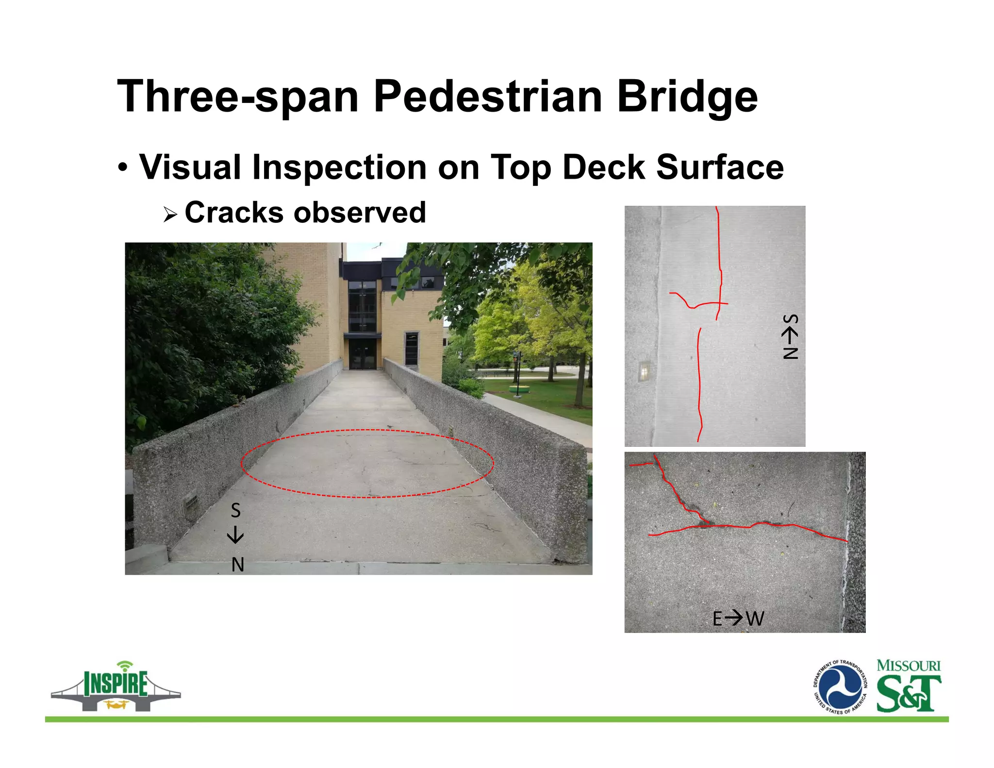
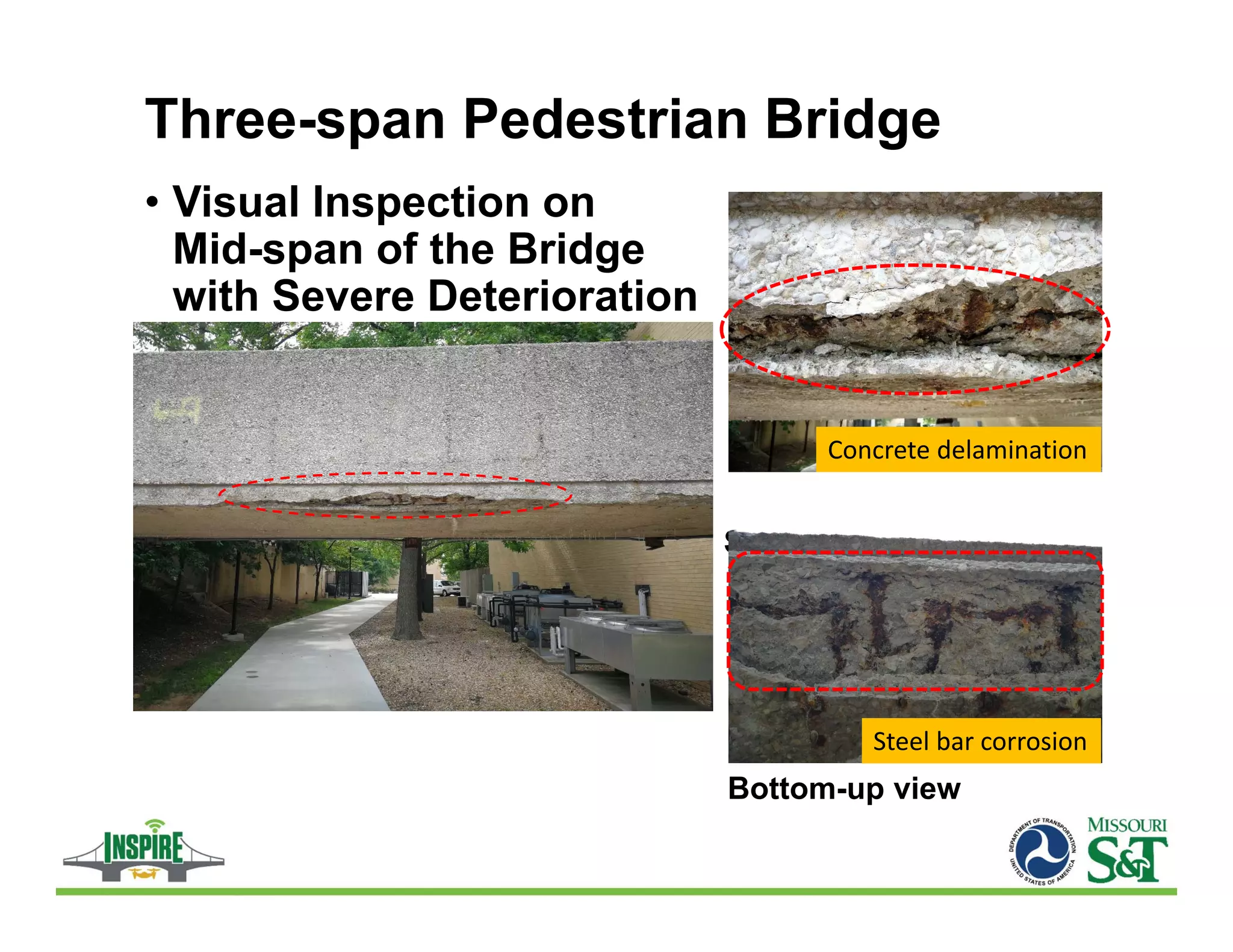
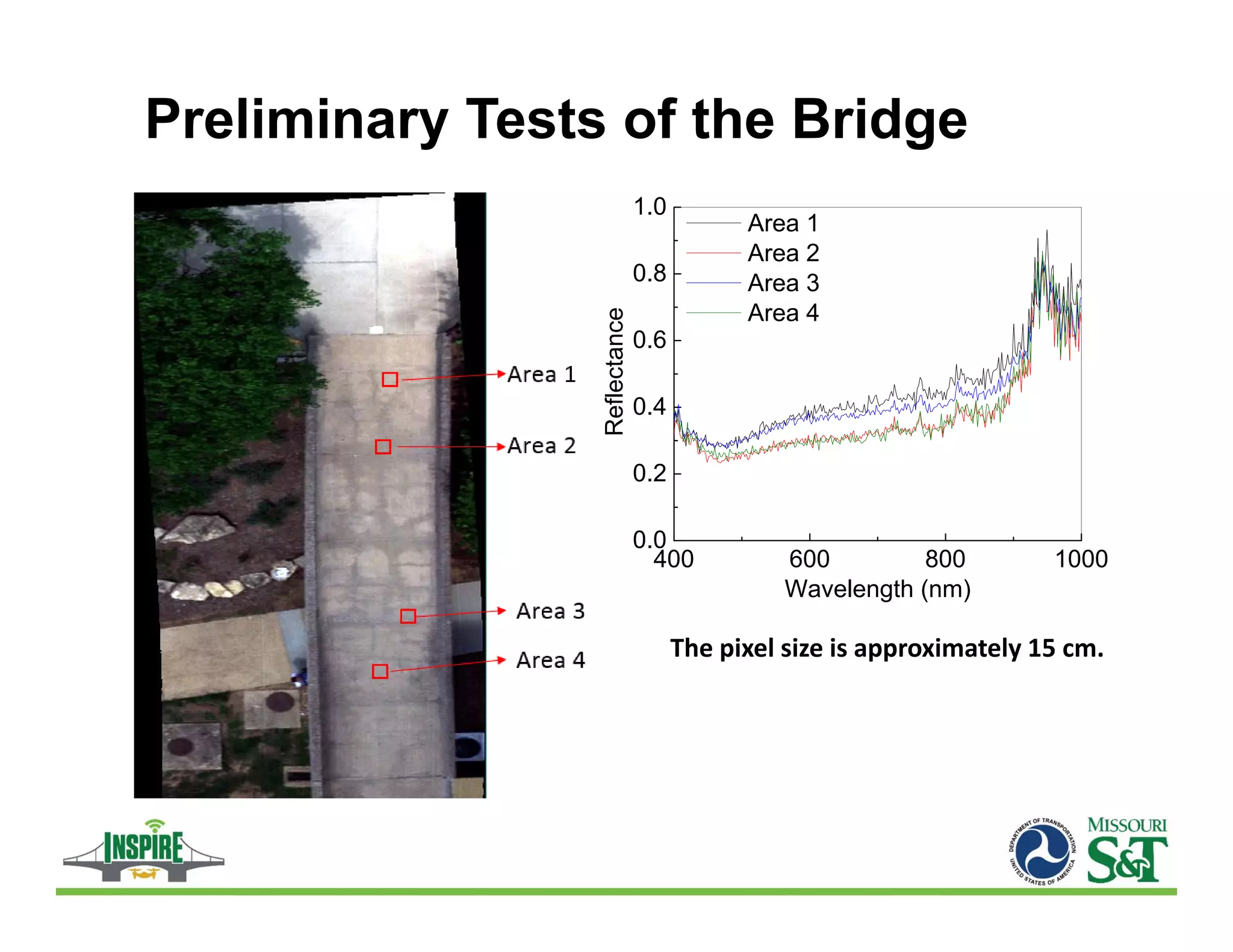
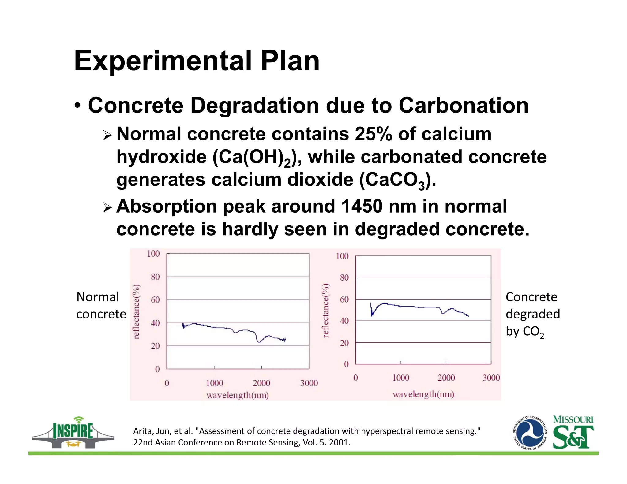
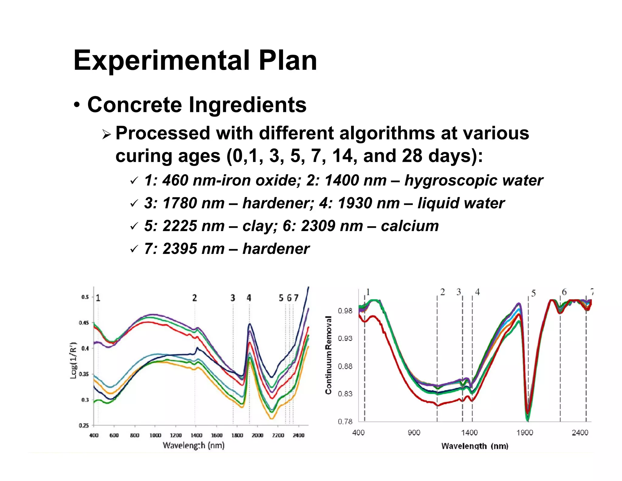
INSPECTING AND PRESERVING
INFRASTRUCTURE THROUGH
ROBOTIC EXPLORATION
Hyperspectral Image Analysis for
Mechanical and Chemical Properties
of Concrete and Steel Surfaces
Genda Chen*, Ph.D., P.E., and Hongyan Ma, Ph.D.
Liang Fan, Paul Manley, Huaishuai Shang, and Abadullah Alhaj
* Professor and INSPIRE UTC Director, Missouri S&T
August 14, 2018
Outline of This Presentation
• Introduction
• Hyperspectral Imaging
• Dual VNIR-SWIR Camera
• Laboratory Tests
• Preliminary Tests of Three-span Bridge
• Experimental Plan for Future Tests
• Concluding Remarks
Introduction
• Bridge Deterioration (2017 ASCE Report)
 39% and 15% of 614,387 bridges
in the U.S. are more than 50 years
and 40 to 49 years, respectively.
• Main Cause of Deterioration
 Steel corrosion
 Monitoring and prevention
 Half-cell potential measures the
potential difference between
steel and reference electrode.
 Corrosion can be prevented by
introducing cathodic protection.
https://metallisation.com/app
lications/ cathodic‐protection‐
of‐steel‐in‐concrete/
https://www.pressherald.com/2016/
10/11/bath‐viaduct‐project‐begins‐
to‐divert‐traffic‐for‐months/
Introduction
• The current practice of visual inspection
is time-consuming, traffic disruptive, and
subjective, leading to inconsistent
reporting.
• A hyperspectral camera can potentially
supplement visual inspection with
quantifiable and reliable imagery.
It can be used to characterize physical
and chemical features (e.g., concrete
crack and steel corrosion).
Introduction
• Applications of hyperspectral imaging in
construction materials and structures are
limited.
• Most researches focused on recycled
concrete aggregate control, concrete
drilling core, concrete compressive
strength.
• Corrosion and carbonation induced
concrete degradation has never been
systematically studied before.
INTRODUCTION
• This project aims to
 Develop an open-source catalogue of concrete
and steel surfaces and their spectral/spatial
features through hyperspectral imaging.
 Develop/train a multi-class classification or
regression classifier through machine learning.
 Validate the classifier as a decision-making tool
for the assessment of concrete crack and
degradation processes, in-situ concrete
properties, and corrosion process in steel
bridge.
Hyperspectral Imaging
• The Method
 Hyperspectral imaging is based on light
reflectance from an exposed surface (long and
narrow like a ‘line’) of concrete or steel
members. As a hyperspectral camera moves in
a direction perpendicular to the ‘line’, the entire
surface of a structural member can be scanned.
For each pixel in the scanned area, spectral
analysis is made to determine spectral
signatures of the scanned surface, such as
characteristic wavelength at absorption peaks.
These features, uniquely associated with certain
materials/chemical bonds, can be used to
identify the chemicals generated during
corrosion process.
Hyperspectral Imaging
• Example Images in Agriculture Application
https://www.google.com/search?q=hyperspectral+imaging+principle&client=firefox‐b‐1‐
ab&tbm=isch&source=iu&ictx=1&fir=YPRSxCEbscaj7M%253A%252C9FJ4kfE_mrjmRM%252C_&usg=AFrqEzd1XFXXtgMYq7
hoTH_rVWInuIl71w&sa=X&ved=2ahUKEwiqrNqMoubcAhVSjqQKHfJSC7gQ9QEwBXoECAUQBg#imgrc=_UStnno6WrlxWM:
Camera setup at optimal measurement distance
Imaging as camera moves at constant speed
Hyperspectral image processing with reflectance calibration
Machine learning for interesting feature extraction
Classification of structural condition from reference imagery
Hyperspectral Imaging
• The Flowchart of Structural Condition
Assessment with Hyperspectral Imaging
Hyperspectral Imaging
• Characteristic Spectral Feature of Various
Types of Materials (from Jet Propulsion)
Co-aligned Dual VNIR-SWIR Camera
• Specifications
 The airborne sensor package measures
approximately 10.7” x 8.2” x 6.5” in size and
weighs approximately 6.25 lb.
 Spectral range
 400-1000 nm (VNIR)
 900-2500 nm (SWIR)
 Max frame rate
 330 Hz (VNIR)
 >100 Hz (SWIR)
Co-aligned Dual VNIR-SWIR Camera
• Focus Distance Selection
 Focus of imagers set at 4 ft. NOTE: airborne
lenses are designed for infinity focus.
 Hyperspectral scans of high contrast targets
taken at 4 ft, 5 ft and 6 ft
 Images zoomed in to show the quality of focus
at vertical edges
 Metric: best focus = 1 transition pixel from white
to dark
 VNIR images show “good” focus for 4 ft, 5 ft
and a little worse for 6 ft
 SWIR images show a quicker loss of focus than
VNIR. For sharp SWIR imagery, it is recommend
to remain within 6” of optimal focus distance.
• VNIR Lens Focused at ~4 Ft
Target distance = 4ft
~ 1 transition pixel
Target distance = 5ft
~1+ transition pixel
Target distance = 6ft
~2 transition pixels
Co-aligned Dual VNIR-SWIR Camera
• SWIR Lens Focused at ~4 Ft
Target distance = 4ft
~1 transition pixel
Target distance = 5ft
~2+ transition pixels
Target distance = 6ft
~3 transition pixels
Co-aligned Dual VNIR-SWIR Camera
Laboratory Tests
• Corrosion Test Setup
 The bottom ¼ height of each 36 cm × 18 cm × 9
cm specimen was immersed in salt solution.
 Accelerated corrosion test was carried out by
applying a constant current to steel bars with a
current density of 500 µA/cm2 until the mass
loss of the steel bars reached 2%.
 Steel bars with impressed current were
corroded, resulting in concrete cracking and
appearance of corrosion
dust due to increasing
volume of corrosion
products.
Laboratory Tests
• Hyperspectral Imaging Setup with a VNIR
Camera
 The camera was set up 2 m above the concrete
specimens.
 The camera scanned at a constant speed of
0.127 m/s.
 For the VNIR camera,
both the exposure time
and the frame period
are 0.167 s.
Pixel size ≈ 2.25 cm
Laboratory Tests
• Reflectance Spectra of Representative
Pixels on the Top Surface of Specimen
400 600 800 1000
0.0
0.2
0.4
0.6
0.8
Reflectance
Wavelength(nm)
Concrete
400 600 800 1000
0.0
0.2
0.4
0.6
0.8
Wavelength(nm)
Reflectance
Corrosion products
400 600 800 1000
0.0
0.2
0.4
0.6
0.8
Wavelength(nm)
Reflectance
Corrosion+crack
Crack
Corrosion-
induced
longitudinal
crack
Laboratory Tests
• Reflectance Spectra of Representative
Pixels on the Side Surface of Specimen
400 600 800 1000
0.0
0.2
0.4
0.6
0.8
Wavelength(nm)
Reflectance
Dry Concrete
400 600 800 1000
0.0
0.2
0.4
0.6
0.8
Wavelength(nm)
Reflectance
Wet Concrete
400 600 800 1000
0.0
0.2
0.4
0.6
0.8
Wavelength(nm)
Reflectance
Corrosion
Corrosion-
induced
longitudinal
crack
Laboratory Tests
• Reflectance Summary at Characteristic
Wavelengths
 Top surface
 Side surface
Reflectance
Wavelength
Concrete Corrosion Products
510 nm 0.48 0.16
890 nm 0.46 0.35
Reflectance
Wavelength
Dry
Concrete
Wet
Concrete
Corrosion
Products
510 nm 0.37 0.28 0.39
890 nm 0.33 0.29 0.59
Three-span Pedestrian Bridge
• Visual Inspection on Top Deck Surface
 Cracks observed
NS
EW
S
N

Three-span Pedestrian Bridge
• Visual Inspection on
Mid-span of the Bridge
with Severe Deterioration
 Side view

Concrete delamination
Steel bar corrosion
Bottom-up view
Three-span Pedestrian Bridge
• Bridge Deck Markup for Nondestructive Tests
Preliminary Tests of the Bridge
400 600 800 1000
0.0
0.2
0.4
0.6
0.8
1.0
Reflectance
Wavelength (nm)
Area 1
Area 2
Area 3
Area 4
The pixel size is approximately 15 cm. 
Experimental Plan
• Influence of Key Operation Parameters
 Determine the pixel sizes corresponding to
various measurement distances and the optimal
exposure time and frame rate.
 Evaluate the detection precision and sensitivity
using standard samples with known material
composition and grain sizes.
 Compare reflectance spectra from various
samples to understand the influence of the
parameters under investigation.
Experimental Plan
• 1st Set of Tests
 Small plain concrete slabs with various water-
to-cement ratios of 0.4, 0.5, and 0.6 will be cast
and cured for 28 days, and subjected to
carbonation for various exposure periods (thus
carbonation depths).
 Hyperspectral image will be taken, and the
depth of carbonation will be determined by
phenolphthalein.
 The surface reflectance spectra at each pixel of
an image will be related to the extent of
carbonation.
Experimental Plan
• Concrete Degradation due to Carbonation
 Normal concrete contains 25% of calcium
hydroxide (Ca(OH)2), while carbonated concrete
generates calcium dioxide (CaCO3).
 Absorption peak around 1450 nm in normal
concrete is hardly seen in degraded concrete.
Concrete
degraded 
by CO2
Normal 
concrete
Arita, Jun, et al. "Assessment of concrete degradation with hyperspectral remote sensing." 
22nd Asian Conference on Remote Sensing, Vol. 5. 2001.
Experimental Plan
• Concrete Ingredients
 Processed with different algorithms at various
curing ages (0,1, 3, 5, 7, 14, and 28 days):
 1: 460 nm-iron oxide; 2: 1400 nm – hygroscopic water
 3: 1780 nm – hardener; 4: 1930 nm – liquid water
 5: 2225 nm – clay; 6: 2309 nm – calcium
 7: 2395 nm – hardener
Experimental Plan
• 2nd Set of Tests
 Steel reinforcing bars embedded in slab
specimens will be impressed with electrical
current to attain various levels of corrosion.
 The reflectance spectra will be obtained during
the whole accelerated corrosion tests.
 The reflectance spectra obtained on the surface
of the slabs will be related to the degree of steel
corrosion (chemical change on the surface of
the specimens).
Experimental Plan
• Main spatial and spectral features will be
extracted from the obtained images. The
imagery will be divided into a large training
set and a small validation set.
• Hyperspectral imaging classification
models will be built based on the training
set and verified by the validation set.
Concluding Remarks
• Hyperspectral imaging obtains a reflectance
spectrum of each pixel to characterize physical
defects or chemical features of structural
degradation.
• Preliminary tests indicated different
characteristic wavelengths at location of
wet/dry concrete, corrosion rust, and crack.
• The characteristic features can be mapped
over the entire area of an image to understand
the degradation extent of specimens.
• Classification models can be built to predict
the degree of concrete degradation.
Acknowledgement
• Financial support for this INSPIRE UTC project is
provided by the U.S. Department of Transportation,
Office of the Assistant Secretary for Research and
Technology (USDOT/OST-R) under Grant No.
69A3551747126 through INSPIRE University
Transportation Center (http://inspire-utc.mst.edu)
at Missouri University of Science and Technology.
The views, opinions, findings and conclusions
reflected in this publication are solely those of the
authors and do not represent the official policy or
position of the USDOT/OST-R, or any State or other
entity.

Hyperspectral Image Analysis for Mechanical and Chemical Properti.pdf

  • 1.
    INSPECTING AND PRESERVING INFRASTRUCTURETHROUGH ROBOTIC EXPLORATION Hyperspectral Image Analysis for Mechanical and Chemical Properties of Concrete and Steel Surfaces Genda Chen*, Ph.D., P.E., and Hongyan Ma, Ph.D. Liang Fan, Paul Manley, Huaishuai Shang, and Abadullah Alhaj * Professor and INSPIRE UTC Director, Missouri S&T August 14, 2018
  • 2.
    Outline of ThisPresentation • Introduction • Hyperspectral Imaging • Dual VNIR-SWIR Camera • Laboratory Tests • Preliminary Tests of Three-span Bridge • Experimental Plan for Future Tests • Concluding Remarks
  • 3.
    Introduction • Bridge Deterioration(2017 ASCE Report)  39% and 15% of 614,387 bridges in the U.S. are more than 50 years and 40 to 49 years, respectively. • Main Cause of Deterioration  Steel corrosion  Monitoring and prevention  Half-cell potential measures the potential difference between steel and reference electrode.  Corrosion can be prevented by introducing cathodic protection. https://metallisation.com/app lications/ cathodic‐protection‐ of‐steel‐in‐concrete/ https://www.pressherald.com/2016/ 10/11/bath‐viaduct‐project‐begins‐ to‐divert‐traffic‐for‐months/
  • 4.
    Introduction • The currentpractice of visual inspection is time-consuming, traffic disruptive, and subjective, leading to inconsistent reporting. • A hyperspectral camera can potentially supplement visual inspection with quantifiable and reliable imagery. It can be used to characterize physical and chemical features (e.g., concrete crack and steel corrosion).
  • 5.
    Introduction • Applications ofhyperspectral imaging in construction materials and structures are limited. • Most researches focused on recycled concrete aggregate control, concrete drilling core, concrete compressive strength. • Corrosion and carbonation induced concrete degradation has never been systematically studied before.
  • 6.
    INTRODUCTION • This projectaims to  Develop an open-source catalogue of concrete and steel surfaces and their spectral/spatial features through hyperspectral imaging.  Develop/train a multi-class classification or regression classifier through machine learning.  Validate the classifier as a decision-making tool for the assessment of concrete crack and degradation processes, in-situ concrete properties, and corrosion process in steel bridge.
  • 7.
    Hyperspectral Imaging • TheMethod  Hyperspectral imaging is based on light reflectance from an exposed surface (long and narrow like a ‘line’) of concrete or steel members. As a hyperspectral camera moves in a direction perpendicular to the ‘line’, the entire surface of a structural member can be scanned. For each pixel in the scanned area, spectral analysis is made to determine spectral signatures of the scanned surface, such as characteristic wavelength at absorption peaks. These features, uniquely associated with certain materials/chemical bonds, can be used to identify the chemicals generated during corrosion process.
  • 8.
    Hyperspectral Imaging • ExampleImages in Agriculture Application https://www.google.com/search?q=hyperspectral+imaging+principle&client=firefox‐b‐1‐ ab&tbm=isch&source=iu&ictx=1&fir=YPRSxCEbscaj7M%253A%252C9FJ4kfE_mrjmRM%252C_&usg=AFrqEzd1XFXXtgMYq7 hoTH_rVWInuIl71w&sa=X&ved=2ahUKEwiqrNqMoubcAhVSjqQKHfJSC7gQ9QEwBXoECAUQBg#imgrc=_UStnno6WrlxWM:
  • 9.
    Camera setup atoptimal measurement distance Imaging as camera moves at constant speed Hyperspectral image processing with reflectance calibration Machine learning for interesting feature extraction Classification of structural condition from reference imagery Hyperspectral Imaging • The Flowchart of Structural Condition Assessment with Hyperspectral Imaging
  • 10.
    Hyperspectral Imaging • CharacteristicSpectral Feature of Various Types of Materials (from Jet Propulsion)
  • 11.
    Co-aligned Dual VNIR-SWIRCamera • Specifications  The airborne sensor package measures approximately 10.7” x 8.2” x 6.5” in size and weighs approximately 6.25 lb.  Spectral range  400-1000 nm (VNIR)  900-2500 nm (SWIR)  Max frame rate  330 Hz (VNIR)  >100 Hz (SWIR)
  • 12.
    Co-aligned Dual VNIR-SWIRCamera • Focus Distance Selection  Focus of imagers set at 4 ft. NOTE: airborne lenses are designed for infinity focus.  Hyperspectral scans of high contrast targets taken at 4 ft, 5 ft and 6 ft  Images zoomed in to show the quality of focus at vertical edges  Metric: best focus = 1 transition pixel from white to dark  VNIR images show “good” focus for 4 ft, 5 ft and a little worse for 6 ft  SWIR images show a quicker loss of focus than VNIR. For sharp SWIR imagery, it is recommend to remain within 6” of optimal focus distance.
  • 13.
    • VNIR LensFocused at ~4 Ft Target distance = 4ft ~ 1 transition pixel Target distance = 5ft ~1+ transition pixel Target distance = 6ft ~2 transition pixels Co-aligned Dual VNIR-SWIR Camera
  • 14.
    • SWIR LensFocused at ~4 Ft Target distance = 4ft ~1 transition pixel Target distance = 5ft ~2+ transition pixels Target distance = 6ft ~3 transition pixels Co-aligned Dual VNIR-SWIR Camera
  • 15.
    Laboratory Tests • CorrosionTest Setup  The bottom ¼ height of each 36 cm × 18 cm × 9 cm specimen was immersed in salt solution.  Accelerated corrosion test was carried out by applying a constant current to steel bars with a current density of 500 µA/cm2 until the mass loss of the steel bars reached 2%.  Steel bars with impressed current were corroded, resulting in concrete cracking and appearance of corrosion dust due to increasing volume of corrosion products.
  • 16.
    Laboratory Tests • HyperspectralImaging Setup with a VNIR Camera  The camera was set up 2 m above the concrete specimens.  The camera scanned at a constant speed of 0.127 m/s.  For the VNIR camera, both the exposure time and the frame period are 0.167 s. Pixel size ≈ 2.25 cm
  • 17.
    Laboratory Tests • ReflectanceSpectra of Representative Pixels on the Top Surface of Specimen 400 600 800 1000 0.0 0.2 0.4 0.6 0.8 Reflectance Wavelength(nm) Concrete 400 600 800 1000 0.0 0.2 0.4 0.6 0.8 Wavelength(nm) Reflectance Corrosion products 400 600 800 1000 0.0 0.2 0.4 0.6 0.8 Wavelength(nm) Reflectance Corrosion+crack Crack Corrosion- induced longitudinal crack
  • 18.
    Laboratory Tests • ReflectanceSpectra of Representative Pixels on the Side Surface of Specimen 400 600 800 1000 0.0 0.2 0.4 0.6 0.8 Wavelength(nm) Reflectance Dry Concrete 400 600 800 1000 0.0 0.2 0.4 0.6 0.8 Wavelength(nm) Reflectance Wet Concrete 400 600 800 1000 0.0 0.2 0.4 0.6 0.8 Wavelength(nm) Reflectance Corrosion Corrosion- induced longitudinal crack
  • 19.
    Laboratory Tests • ReflectanceSummary at Characteristic Wavelengths  Top surface  Side surface Reflectance Wavelength Concrete Corrosion Products 510 nm 0.48 0.16 890 nm 0.46 0.35 Reflectance Wavelength Dry Concrete Wet Concrete Corrosion Products 510 nm 0.37 0.28 0.39 890 nm 0.33 0.29 0.59
  • 20.
    Three-span Pedestrian Bridge •Visual Inspection on Top Deck Surface  Cracks observed NS EW S N 
  • 21.
    Three-span Pedestrian Bridge •Visual Inspection on Mid-span of the Bridge with Severe Deterioration  Side view  Concrete delamination Steel bar corrosion Bottom-up view
  • 22.
    Three-span Pedestrian Bridge •Bridge Deck Markup for Nondestructive Tests
  • 23.
    Preliminary Tests ofthe Bridge 400 600 800 1000 0.0 0.2 0.4 0.6 0.8 1.0 Reflectance Wavelength (nm) Area 1 Area 2 Area 3 Area 4 The pixel size is approximately 15 cm. 
  • 24.
    Experimental Plan • Influenceof Key Operation Parameters  Determine the pixel sizes corresponding to various measurement distances and the optimal exposure time and frame rate.  Evaluate the detection precision and sensitivity using standard samples with known material composition and grain sizes.  Compare reflectance spectra from various samples to understand the influence of the parameters under investigation.
  • 25.
    Experimental Plan • 1stSet of Tests  Small plain concrete slabs with various water- to-cement ratios of 0.4, 0.5, and 0.6 will be cast and cured for 28 days, and subjected to carbonation for various exposure periods (thus carbonation depths).  Hyperspectral image will be taken, and the depth of carbonation will be determined by phenolphthalein.  The surface reflectance spectra at each pixel of an image will be related to the extent of carbonation.
  • 26.
    Experimental Plan • ConcreteDegradation due to Carbonation  Normal concrete contains 25% of calcium hydroxide (Ca(OH)2), while carbonated concrete generates calcium dioxide (CaCO3).  Absorption peak around 1450 nm in normal concrete is hardly seen in degraded concrete. Concrete degraded  by CO2 Normal  concrete Arita, Jun, et al. "Assessment of concrete degradation with hyperspectral remote sensing."  22nd Asian Conference on Remote Sensing, Vol. 5. 2001.
  • 27.
    Experimental Plan • ConcreteIngredients  Processed with different algorithms at various curing ages (0,1, 3, 5, 7, 14, and 28 days):  1: 460 nm-iron oxide; 2: 1400 nm – hygroscopic water  3: 1780 nm – hardener; 4: 1930 nm – liquid water  5: 2225 nm – clay; 6: 2309 nm – calcium  7: 2395 nm – hardener
  • 28.
    Experimental Plan • 2ndSet of Tests  Steel reinforcing bars embedded in slab specimens will be impressed with electrical current to attain various levels of corrosion.  The reflectance spectra will be obtained during the whole accelerated corrosion tests.  The reflectance spectra obtained on the surface of the slabs will be related to the degree of steel corrosion (chemical change on the surface of the specimens).
  • 29.
    Experimental Plan • Mainspatial and spectral features will be extracted from the obtained images. The imagery will be divided into a large training set and a small validation set. • Hyperspectral imaging classification models will be built based on the training set and verified by the validation set.
  • 30.
    Concluding Remarks • Hyperspectralimaging obtains a reflectance spectrum of each pixel to characterize physical defects or chemical features of structural degradation. • Preliminary tests indicated different characteristic wavelengths at location of wet/dry concrete, corrosion rust, and crack. • The characteristic features can be mapped over the entire area of an image to understand the degradation extent of specimens. • Classification models can be built to predict the degree of concrete degradation.
  • 31.
    Acknowledgement • Financial supportfor this INSPIRE UTC project is provided by the U.S. Department of Transportation, Office of the Assistant Secretary for Research and Technology (USDOT/OST-R) under Grant No. 69A3551747126 through INSPIRE University Transportation Center (http://inspire-utc.mst.edu) at Missouri University of Science and Technology. The views, opinions, findings and conclusions reflected in this publication are solely those of the authors and do not represent the official policy or position of the USDOT/OST-R, or any State or other entity.