Downloaded 80 times

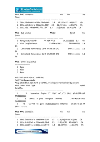

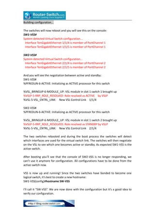
![the switch vrtual link command to tell the switch that the etherchannel is a VSL
interface. Let’s verify that our etherchannel is working between the two switches:
SW1-VSS#show etherchannel summary | incl Po1
1
Po1(RU)
Te1/4(P)
Te1/5(P)
SW2-VSS#show etherchannel summary | incl Po2
2
Po2(RU)
Te1/4(P)
Te1/5(P)
We are now ready to convert the 6500s to VSS.
Execute Conversion
The final step in configuring VSS is to execute the conversion. Once we do this the
switches will reload and 3 things will happen:
The configurations of both switches will be merged into a single
configuration.
The
interface numbers will be renumbered from slot/port to
switch-number/slot/port.
Negotiation to determine which switch is active or standby.
This is how we execute the conversion:
SW1-VSS#switch convert mode virtual
This command will convert all interface names
to naming convention "interface-type switch-number/slot/port",
save the running config to startup-config and
reload the switch.
NOTE: Make sure to configure one or more dual-active detection methods
once the conversion is complete and the switches have come up in VSS mode.
Do you want to proceed? [yes/no]: yes
Converting interface names
Building configuration...
SW2-VSS#switch convert mode virtual
This command will convert all interface names
to naming convention "interface-type switch-number/slot/port",
save the running config to startup-config and
reload the switch.
NOTE: Make sure to configure one or more dual-active detection methods
once the conversion is complete and the switches have come up in VSS mode.
Do you want to proceed? [yes/no]: yes
Converting interface names](https://image.slidesharecdn.com/howtoconfigurecisco6500vss-140224030803-phpapp01/85/How-to-configure-cisco-6500-vss-5-320.jpg)
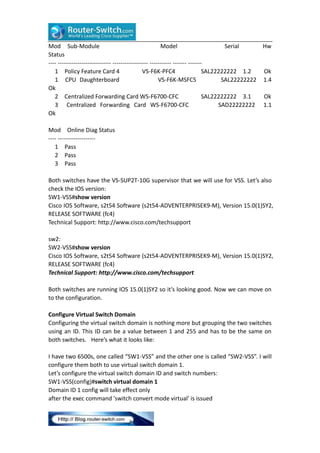
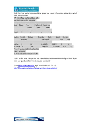
![Verification
The active switch is used to control both switches so some commands have been
changed. For example “show run” can now be used to check the running
configuration from both switches:
SW-VSS#show run switch 1
Building configuration...
Current configuration : 4283 bytes
!
[output omitted]
SW-VSS#show run switch 2
Building configuration...
Current configuration : 4223 bytes
!
[output omitted]
By adding “switch <id>” you can check the running configuration from switch 1 or 2.
There’s also some special VSS commands that we can use:
SW-VSS#show switch virtual
Switch mode
: Virtual Switch
Virtual switch domain number : 1
Local switch number
:1
Local switch operational role: Virtual Switch Active
Peer switch number
:2
Peer switch operational role : Virtual Switch Standby
The show switch virtual command tells us that this switch is active and the other one
is standby. We can also take a closer look at the VSL:
SW-VSS#show switch virtual link
VSL Status : UP
VSL Uptime : 28 minutes
VSL SCP Ping : Pass
VSL ICC Ping : Pass
VSL Control Link : Te1/1/4
VSL Encryption : Configured Mode - Off, Operational Mode - Off
This is how you can check the VSL etherchannel:
SW-VSS#show interfaces vsl
VSL Port-channel: Po1
Port: Te1/1/4
Port: Te1/1/5](https://image.slidesharecdn.com/howtoconfigurecisco6500vss-140224030803-phpapp01/85/How-to-configure-cisco-6500-vss-7-320.jpg)

The document describes how to configure Cisco Catalyst 6500 switches in Virtual Switching System (VSS) mode. Key steps include: 1. Configuring the virtual switch domain ID and assigning switch numbers on each switch to group them. 2. Configuring the virtual switch link interface between the switches, which is used to exchange state information. 3. Executing the "switch convert mode virtual" command on each switch to convert them to VSS mode and reboot the system. This merges the switch configurations, renumbers interfaces, and designates one switch as active and the other as standby.