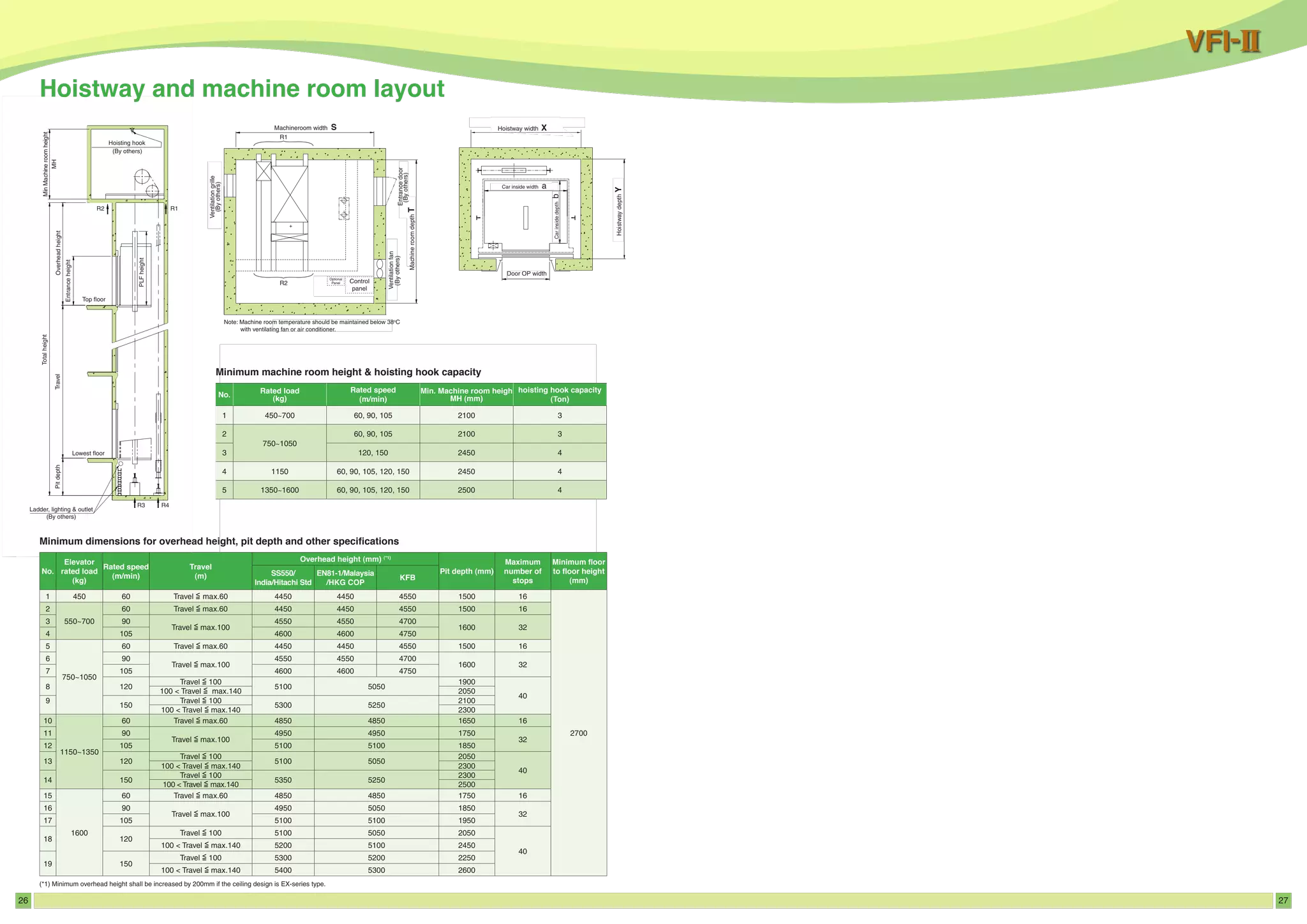
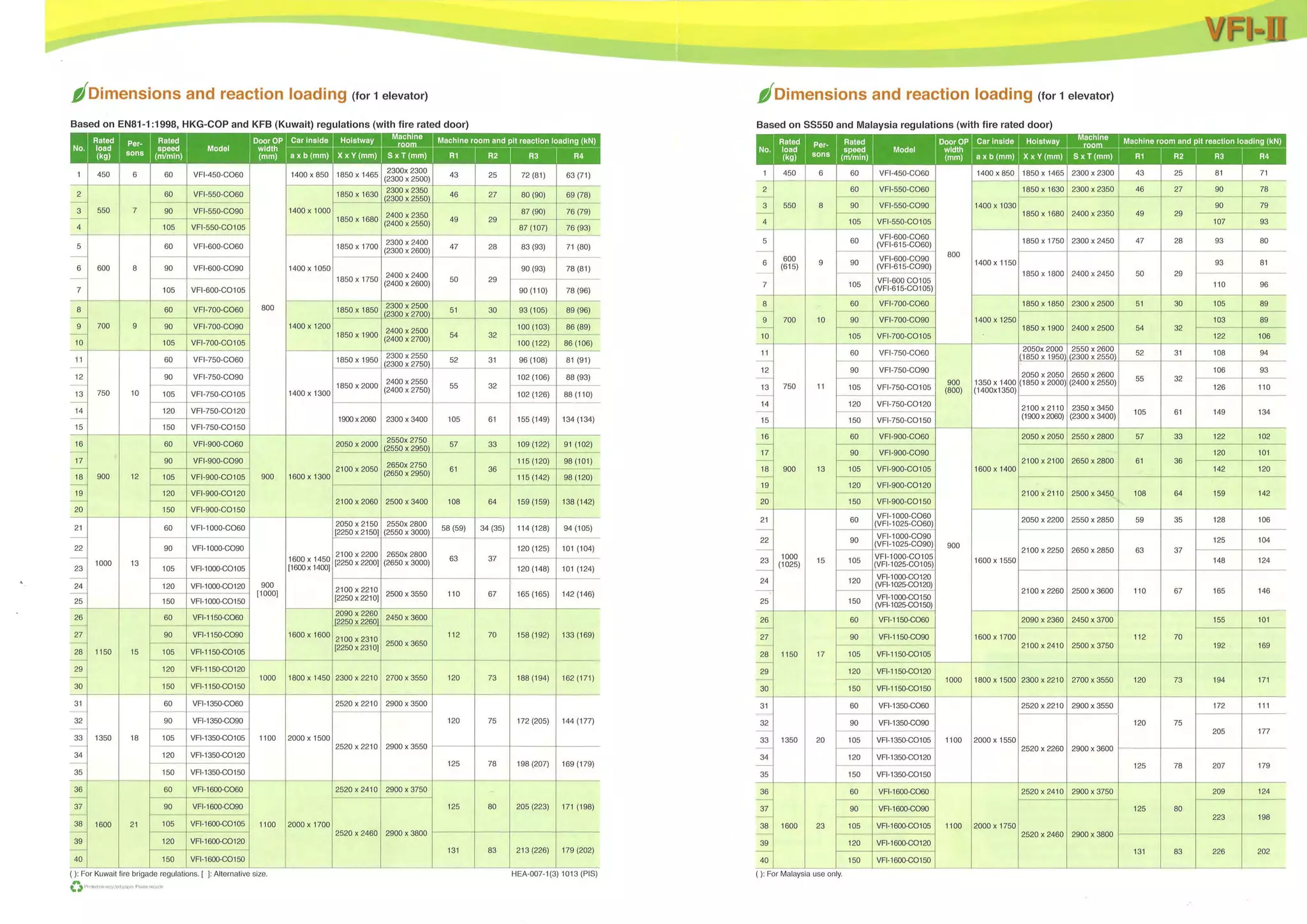
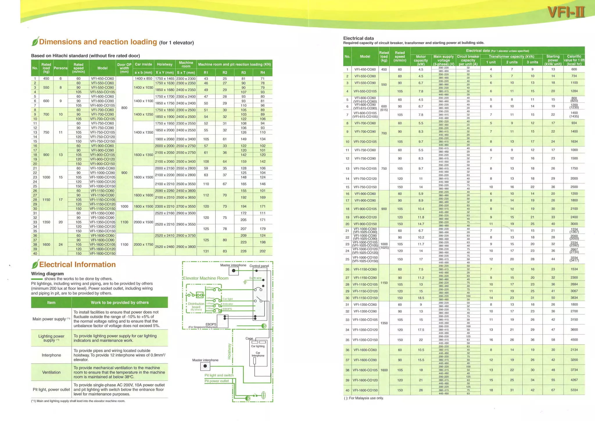
This document provides details on the Hitachi Elevator VFI-II model, including:
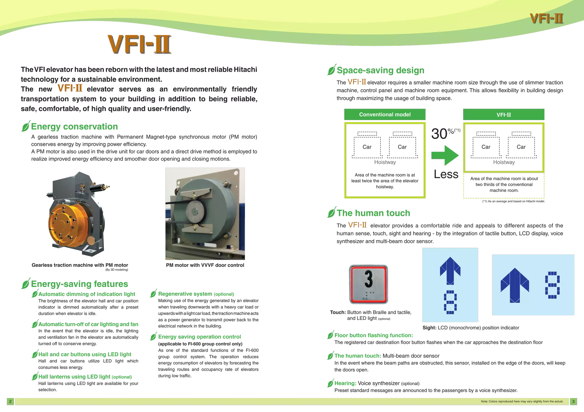
1. It describes several energy saving features such as automatic dimming of lights, turning off lights and fans when idle, and use of LED lights.
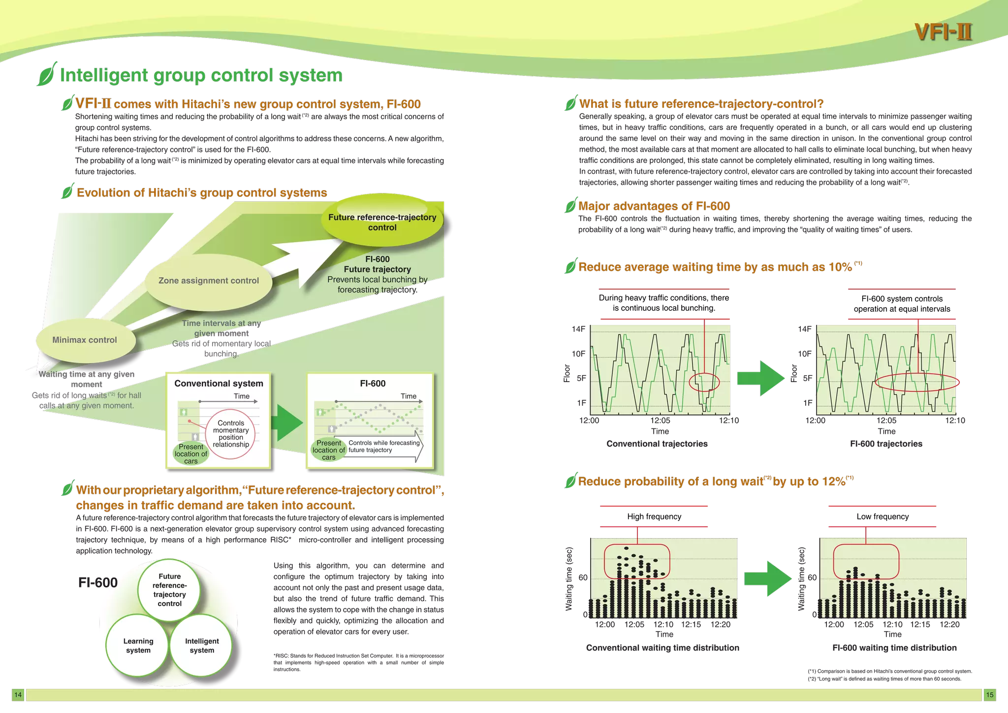
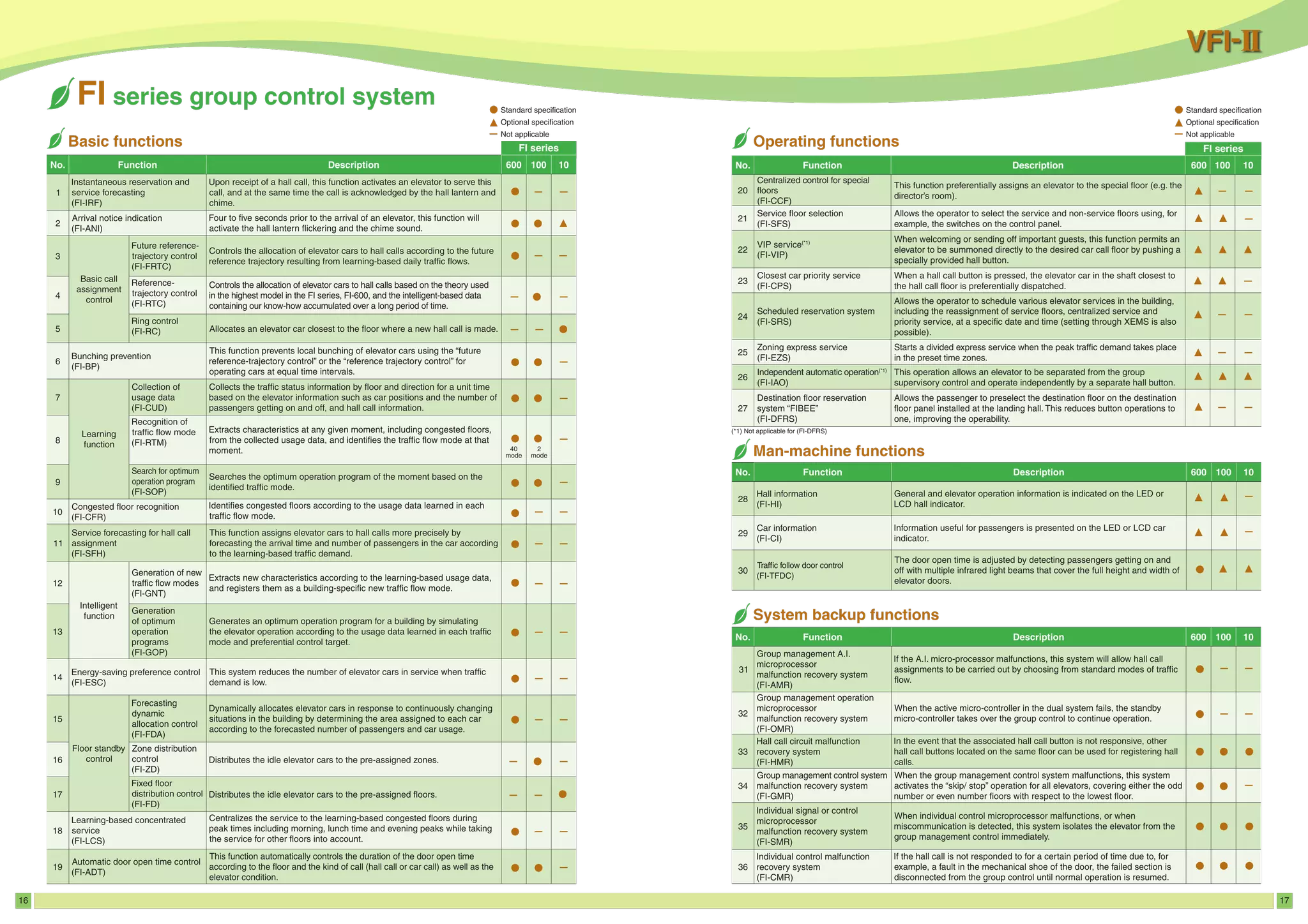
2. It lists optional features like a regenerative system and energy saving operation control for the FI-600 group control.
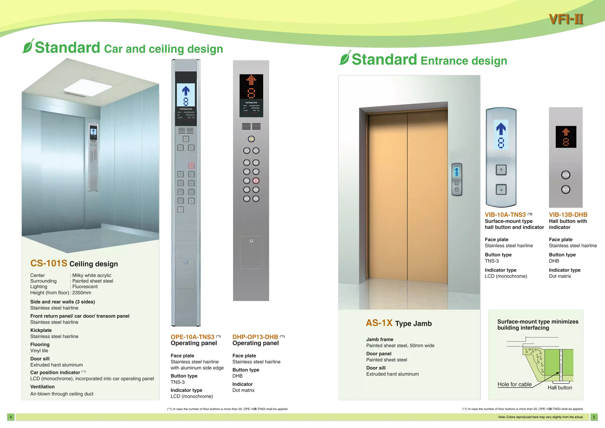
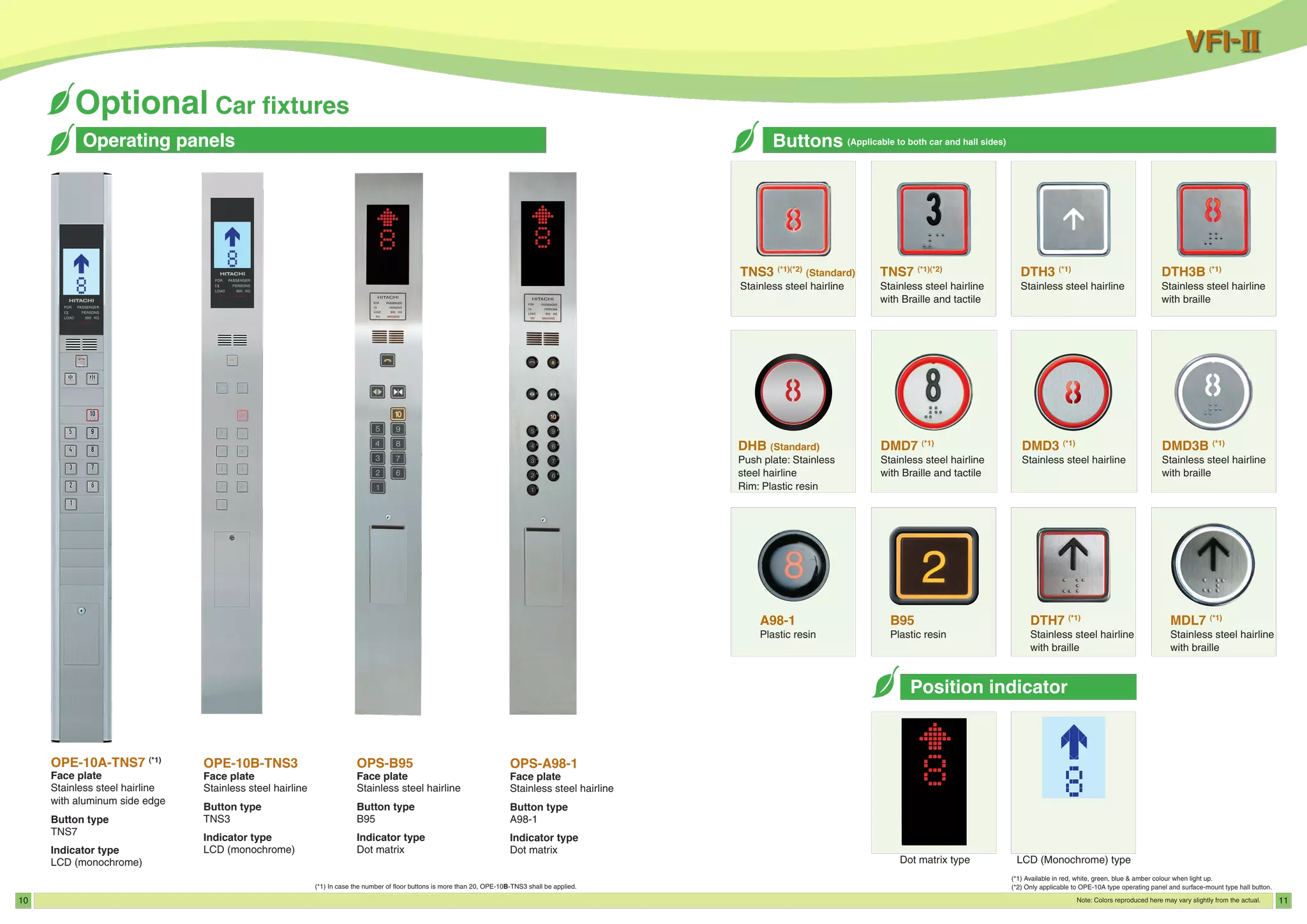
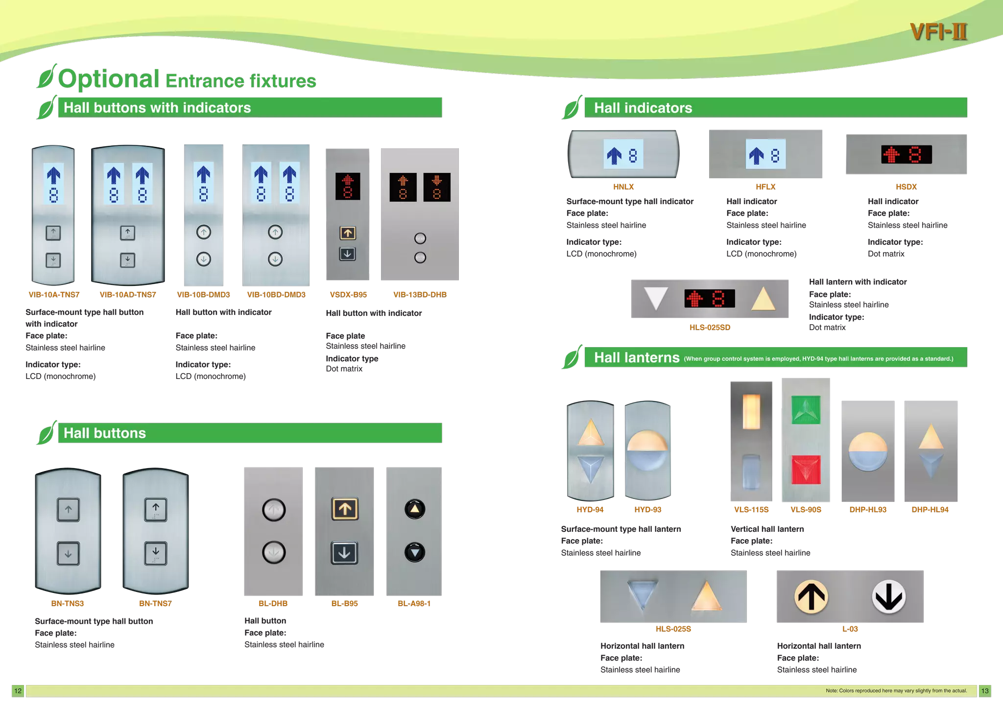
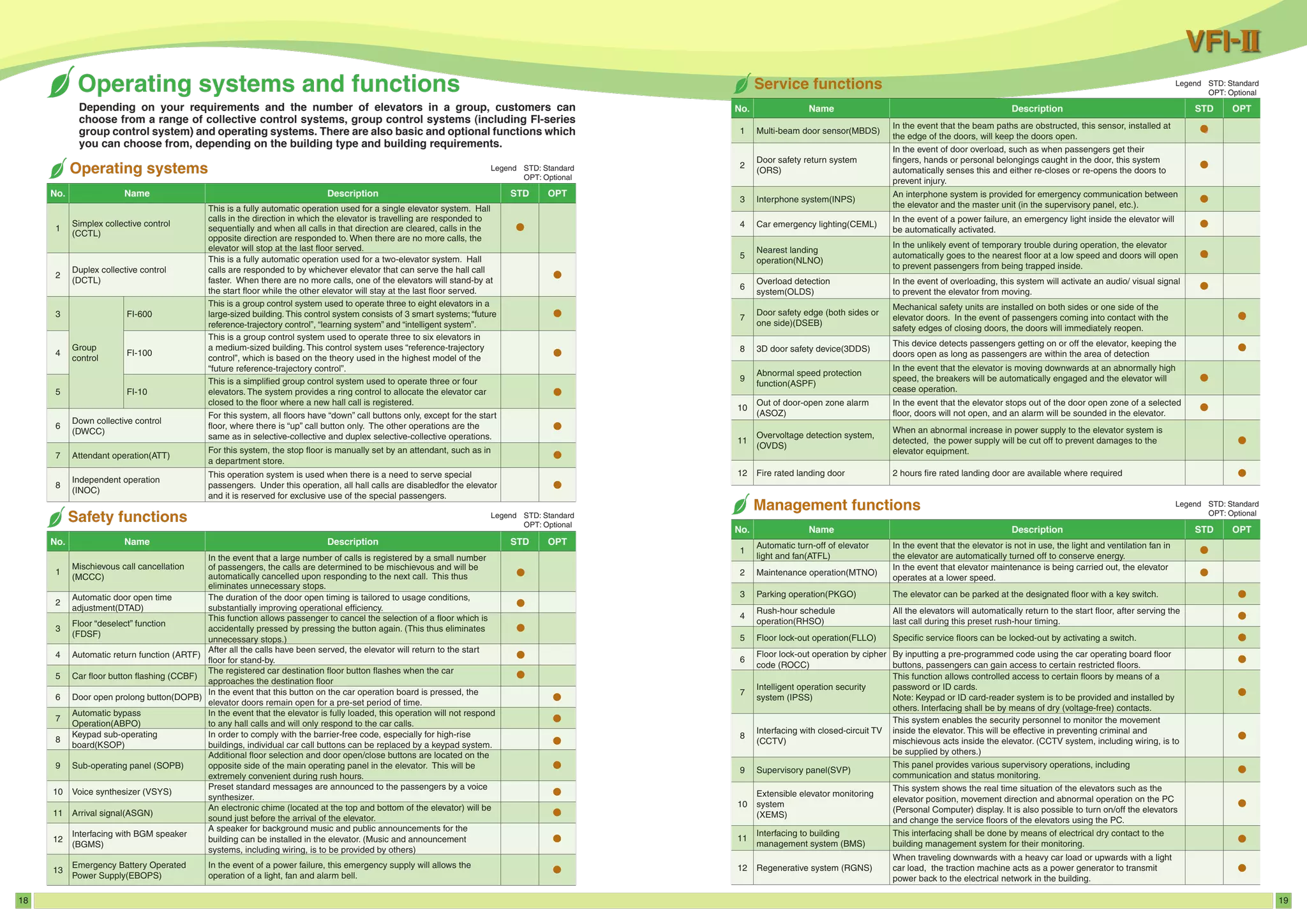
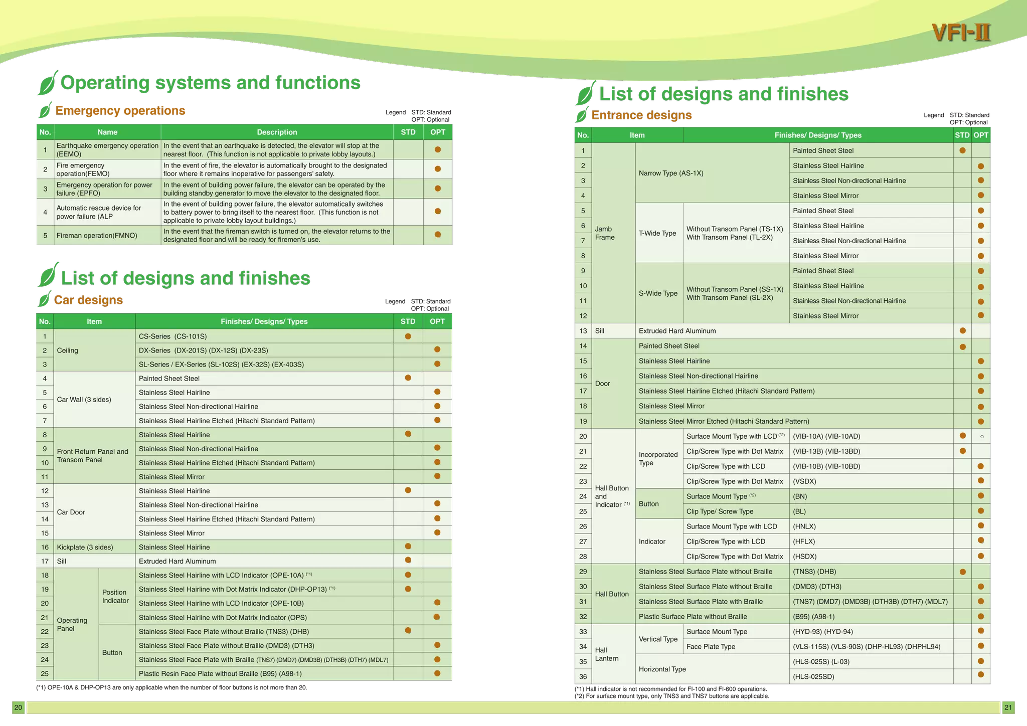
3. It provides an overview of components like cars and ceilings, operating panels, hall buttons, and hall lanterns.


![[BROCHURE] Italy Tour Project | @SlideON](https://cdn.slidesharecdn.com/ss_thumbnails/brochure8-251215152319-2805af68-thumbnail.jpg?width=640&height=640&fit=bounds)


