01/24/2026 3
INTRODUCTION
AC hasbeen the preferred transmission system for the past hundred years, yet
there are some technical limitations when it comes to HVAC transmission for
bulk power transfer over very long distances and connection of asynchronous
grids.
On other hand, High Voltage Direct Current (HVDC) is a technology that
transmits power in forms of DC, to increase the efficiency of bulk power
transmission over long distances.
They allow electricity to flow in both directions so demand and supply are
matched more effectively.
HVDC can interconnect asynchronous systems as well as systems with
different frequencies.
4.
01/24/2026 4
Contd…
The world’sfirst commercial HVDC link situated between the Swedish
mainland and the island Gotland was delivered by ABB in the year of
1954 with the capacity of 20MW, 100 kV.
The longest HVDC link in the world is currently Belo Monte-Rio de
Janeiro transmission line, Brazil – 2,543km
The 2,543km-long Belo Monte-Rio de Janeiro transmission line in
Brazil is an 800kV ultra-high-voltage direct current (UHVDC) line that
transmits electricity from the 11.2GW Belo Monte hydroelectric power
plant located in Para to Rio de Janeiro, Brazil
5.
01/24/2026 5
Need ofHVDC:
As the load demand increases as the time progresses, there
should be two possibilities:
Either to increase the generation
To minimize the losses
The losses are occurred at various levels which are at are
Generating level, transmission level and distribution level
So the losses at transmission level can be greatly reduced by
HVDC transmission.
Long distance transmission
5times more energy transmits than AC(same lines)
Less losses (no inductance, capacitance).
Cost of transmission is low.
Maintenance & operation cost is low.
Initial cost is high but overall cost is lower than ac
Contd…
01/24/2026 7
8.
01/24/2026 8
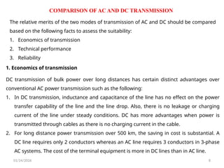
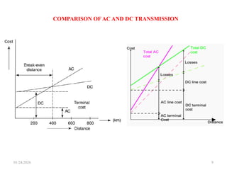
COMPARISON OFAC AND DC TRANSMISSION
The relative merits of the two modes of transmission of AC and DC should be compared
based on the following facts to assess the suitability:
1. Economics of transmission
2. Technical performance
3. Reliability
DC transmission of bulk power over long distances has certain distinct advantages over
conventional AC power transmission such as the following:
1. In DC transmission, inductance and capacitance of the line has no effect on the power
transfer capability of the line and the line drop. Also, there is no leakage or charging
current of the line under steady conditions. DC has more advantages when power is
transmitted through cables as there is no charging current in the cable.
2. For long distance power transmission over 500 km, the saving in cost is substantial. A
DC line requires only 2 conductors whereas an AC line requires 3 conductors in 3-phase
AC systems. The cost of the terminal equipment is more in DC lines than in AC line.
1. Economics of transmission
01/24/2026 10
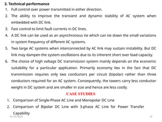
2. Technicalperformance
1. Full control over power transmitted in either direction.
2. The ability to improve the transient and dynamic stability of AC system when
embedded with DC link.
3. Fast control to limit fault currents in DC lines.
4. A DC link can be used as an asynchronous tie which can tie down the small variations
in system frequency of different AC systems.
5. Two large AC systems when interconnected by AC link may sustain instability. But DC
link may dampen the system oscillations due to its inherent short over load capacity.
6. The choice of high voltage DC transmission system mainly depends on the economic
suitability for a particular application. Primarily economy lies in the fact that DC
transmission requires only two conductors per circuit (bipolar) rather than three
conductors required for an AC system. Consequently, the towers carry less conductor
weight in DC system and are smaller in size and hence are less costly.
1. Comparison of Single-Phase AC Line and Monopolar DC Line
2. Comparison of Bipolar DC Line with 3-phase AC Line for Power Transfer
Capability
CASE STUDIES
01/24/2026 13
3. Reliability
Astudy on the existing HVDC links in the world indicates that the reliability of DC
transmission system is quite good and comparable to that of AC systems. The
performance of thyristor valves is much more reliable than mercury arc valves. Further,
developments like direct light triggered thyristor (LTT) and new techniques of control
and protection have improved reliability levels.
14.
ADVANTAGES OF HVDCTRANSMISSION
01/24/2026 14
1. Interconnection of systems using long length of cables in particular while crossing sea
water.
2. Interconnection of systems operating at different frequencies (as asynchronous tie).
3. Reduced transmission losses.
4. Rigid control over the magnitude and direction of power flow with easy reversibility of
power flow.
5. Limiting the transfer of fault current.
6. Damping out oscillations and improving the stability margins when embedded in weak
AC systems of low short circuit ratio (SCR). The strength of AC systems connected to the
terminals of DC links is measured in terms of short circuit ratio (SCR). [SCR is defined as
the AC power transfer under short circuit at the converter bus or rated DC power. If SCR
is less than 3, then AC system is said to be weak.]
7. HVDC transmission is most useful in areas requiring crossing of long waterways like
crossing a sea to feed an island through submarine cables. The first major DC
transmission line was established in 1960 in USSR for transmitting power of 750 MW at
±400 kV, over a distance of 500 km. In USA, a DC line of 1360 km length operating at
±400 kV for transmission of bulk power of l440 MW was established in 1970.
15.
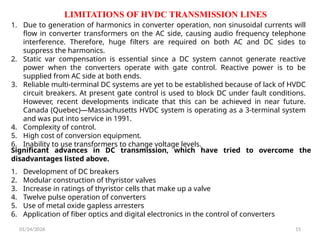
LIMITATIONS OF HVDCTRANSMISSION LINES
01/24/2026 15
1. Due to generation of harmonics in converter operation, non sinusoidal currents will
flow in converter transformers on the AC side, causing audio frequency telephone
interference. Therefore, huge filters are required on both AC and DC sides to
suppress the harmonics.
2. Static var compensation is essential since a DC system cannot generate reactive
power when the converters operate with gate control. Reactive power is to be
supplied from AC side at both ends.
3. Reliable multi-terminal DC systems are yet to be established because of lack of HVDC
circuit breakers. At present gate control is used to block DC under fault conditions.
However, recent developments indicate that this can be achieved in near future.
Canada (Quebec)—Massachusetts HVDC system is operating as a 3-terminal system
and was put into service in 1991.
4. Complexity of control.
5. High cost of conversion equipment.
6. Inability to use transformers to change voltage levels.
Significant advances in DC transmission, which have tried to overcome the
disadvantages listed above.
1. Development of DC breakers
2. Modular construction of thyristor valves
3. Increase in ratings of thyristor cells that make up a valve
4. Twelve pulse operation of converters
5. Use of metal oxide gapless arresters
6. Application of fiber optics and digital electronics in the control of converters
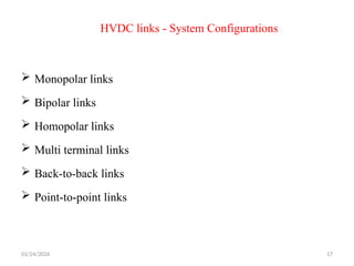
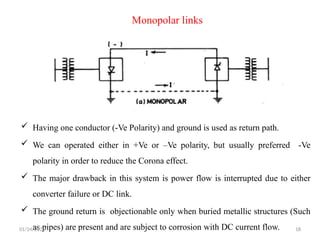
Monopolar links
Havingone conductor (-Ve Polarity) and ground is used as return path.
We can operated either in +Ve or –Ve polarity, but usually preferred -Ve
polarity in order to reduce the Corona effect.
The major drawback in this system is power flow is interrupted due to either
converter failure or DC link.
The ground return is objectionable only when buried metallic structures (Such
as pipes) are present and are subject to corrosion with DC current flow.
01/24/2026 18
19.
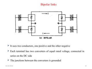
Bipolar links
Ituses two conductors, one positive and the other negative
Each terminal has two converters of equal rated voltage, connected in
series on the DC side
The junctions between the converters is grounded
01/24/2026 19
20.
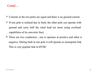
Currents inthe two poles are equal and there is no ground current
If one pole is isolated due to fault, the other pole can operate with
ground and carry half the rated load (or more using overload
capabilities of its converter line)
There are two conductors , one is operates at positive and other is
negative. During fault in one pole it will operate as monopolar link.
This is very popular link in HVDC
01/24/2026 20
Contd…
21.
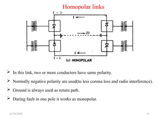
Homopolar links
Inthis link, two or more conductors have same polarity.
Normally negative polarity are used(to less corona loss and radio interference).
Ground is always used as return path.
During fault in one pole it works as monopolar.
01/24/2026 21
22.
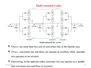
Multi terminal Links
01/24/202622
There are more than two sets of converters like in the bipolar case.
Thus, converters one and three can operate as rectifiers while converter
two operates as an inverter.
Operating in the opposite order, converter two can operate as a rectifier
and converters one and three as inverters
Contd…
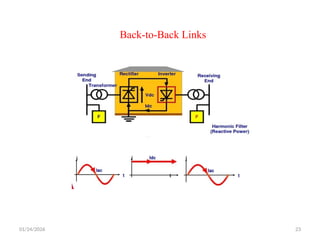
In thiscase the two converter stations are located at
the same site and no transmission line or cable is
required between the converter bridges.
The connection may be monopolar or bipolar.
The dc-link voltage is r egulated by controlling the
power flow to the ac grid.
This system having fast control of the power flow.
01/24/2026 24
25.
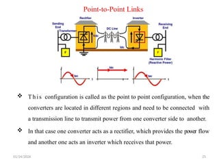
Point-to-Point Links
Thisconfiguration is called as the point to point configuration, when the
converters are located in different regions and need to be connected with
a transmission line to transmit power from one converter side to another.
In that case one converter acts as a rectifier, which provides the power flow
and another one acts an inverter which receives that power.
01/24/2026 25
Contd..
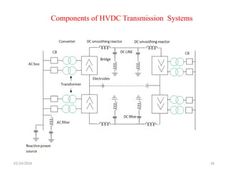
Converters
Smoothingreactors
Harmonic filters
Reactive power supplies
Electrodes
DC lines
AC circuit breakers
01/24/2026 27
28.
Converters:
They performAC/DC and DC/AC conversion
They consist of valve bridges and transformers
Valve bridge consists of high voltage valves connected in a 6-pulse or 12-
pulse arrangement
The transformers are ungrounded such that the DC system will be able to
establish its own reference to ground
01/24/2026 28
They are high reactors with inductance as high as 1 H in series with each
pole They serve the following:
They decrease harmonics in voltages and currents in DC lines
They prevent commutation failures in inverters
Prevent current from being discontinuous for light loads
Smoothing reactors:
29.
Harmonic filters:
Convertersgenerate harmonics in voltages and currents. These harmonics
may cause overheating of capacitors and nearby generators and
interference with telecommunication systems.
Harmonic filters are used to mitigate these harmonics
Reactive power supplies:
Under steady state condition conditions, the reactive power consumed by
the converter is about 50% of the active power transferred
Under transient conditions it could be much higher Reactive power is,
therefore, provided near the converters
For a strong AC power system, this reactive power is provided by a shunt
capacitor
01/24/2026 29
30.
Electrodes:
Electrodes areconductors that provide connection to the earth for neutral.
They have large surface to minimize current densities and surface voltage
gradients
DC lines:
AC circuit breakers
They may be overhead lines or cables
DC lines are very similar to AC lines
They used to clear faults in the transformer and for taking the DC link out
of service
They are not used for clearing DC faults
DC faults are cleared by converter control more rapidly
01/24/2026 30
31.
01/24/2026 31
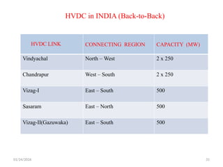
HVDC inINDIA (Back-to-Back)
HVDC LINK CONNECTING REGION CAPACITY (MW)
Vindyachal North – West 2 x 250
Chandrapur West – South 2 x 250
Vizag-I East – South 500
Sasaram East – North 500
Vizag-II(Gazuwaka) East – South 500
32.
01/24/2026 32
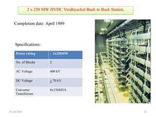
2 x250 MW HVDC Vindhyachal Back to Back Station.
Power rating : 2x250MW
No. of Blocks 2
AC Voltage 400 kV
DC Voltage + 70 kV
Converter
Transformer
8x156MVA
Completion date: April 1989
Specifications:
33.
01/24/2026 33
System Salient
Features:
It connects Vindhyachal Super Thermal
Power Stations (Western Region) to
Singrauli Super Thermal Power Stations
(Northern Region) in Indian Grid.
Each Block power carrying capacity is 250
MW.
Bidirectional power flow capability is
available.
The project achieve load diversity of Northern and
Western region in Indian Grid by meeting high
demand from surplus power available in either
regions
First commercial Back to Back HVDC Station in
India
34.
01/24/2026 34
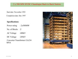
2 x500 MW HVDC Chandrapur Back to Back Station.
Start date: November 1993
Completion date: Dec 1997
Specifications:
Power rating : 2x500MW
No. of Blocks :2
AC Voltage :400kV
DC Voltage :205kV
Converter Transformer:12x234
MVA
35.
01/24/2026 35
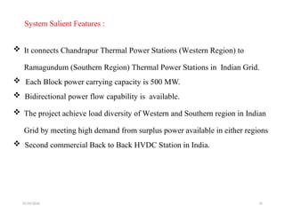
System SalientFeatures :
It connects Chandrapur Thermal Power Stations (Western Region) to
Ramagundum (Southern Region) Thermal Power Stations in Indian Grid.
Each Block power carrying capacity is 500 MW.
Bidirectional power flow capability is available.
The project achieve load diversity of Western and Southern region in Indian
Grid by meeting high demand from surplus power available in either regions
Second commercial Back to Back HVDC Station in India.
36.
01/24/2026 36
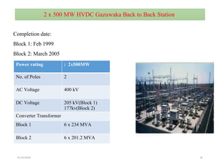
2 x500 MW HVDC Gazuwaka Back to Back Station.
Power rating : 2x500MW
No. of Poles 2
AC Voltage 400 kV
DC Voltage 205 kV(Block 1)
177kv(Block 2)
Converter Transformer
Block 1 6 x 234 MVA
Block 2 6 x 201.2 MVA
Completion date:
Block 1: Feb 1999
Block 2: March 2005
37.
01/24/2026 37
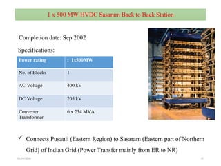
1 x500 MW HVDC Sasaram Back to Back Station
Power rating : 1x500MW
No. of Blocks 1
AC Voltage 400 kV
DC Voltage 205 kV
Converter
Transformer
6 x 234 MVA
Connects Pusauli (Eastern Region) to Sasaram (Eastern part of Northern
Grid) of Indian Grid (Power Transfer mainly from ER to NR)
Completion date: Sep 2002
Specifications:
01/24/2026 39
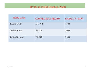
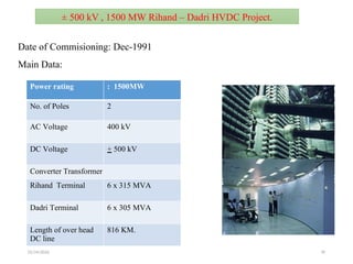
± 500kV , 1500 MW Rihand – Dadri HVDC Project.
Date of Commisioning: Dec-1991
Main Data:
Power rating : 1500MW
No. of Poles 2
AC Voltage 400 kV
DC Voltage + 500 kV
Converter Transformer
Rihand Terminal 6 x 315 MVA
Dadri Terminal 6 x 305 MVA
Length of over head
DC line
816 KM.
40.
01/24/2026 40
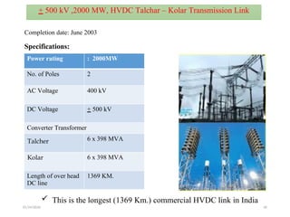
Power rating: 2000MW
No. of Poles 2
AC Voltage 400 kV
DC Voltage + 500 kV
Converter Transformer
Talcher 6 x 398 MVA
Kolar 6 x 398 MVA
Length of over head
DC line
1369 KM.
Completion date: June 2003
This is the longest (1369 Km.) commercial HVDC link in India
+ 500 kV ,2000 MW, HVDC Talchar – Kolar Transmission Link
Specifications:
41.
01/24/2026 41
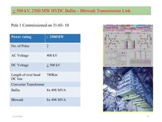
+ 500kV, 2500 MW HVDC Ballia – Bhiwadi Transmission Link
Power rating : 2500MW
No. of Poles 2
AC Voltage 400 kV
DC Voltage + 500 kV
Length of over head
DC line
780Km
Converter Transformer
Ballia 8x 498 MVA
Bhiwadi 8x 498 MVA
Pole 1 Commissioned on 31-03- 10
01/24/2026 45
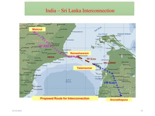
Proposed Routefor Interconnection Anuradhapura
185 Kms
Rameshwaram
90 Kms
Talaimannar
150 Kms
Madurai
India – Sri Lanka Interconnection
46.
01/24/2026 46
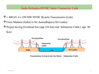
Indo-Srilanka HVDCInter Connecter Link
± 400 kV, 4 x 250 MW HVDC Bi-pole Transmission (Link)
From Madurai (India) to Sri Anuradhapura (Sri Lanka)
Project having Overhead line (app 334 km) and Submarine Cable ( app 90
Km)
India Sri Lanka
Sea
Submarine
Cable
Overhead line Overhead line
Transmission System in the Sea Route : Submarine Cable
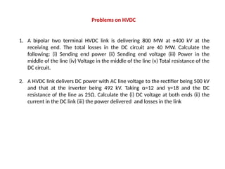
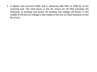
1. A bipolartwo terminal HVDC link is delivering 800 MW at ±400 kV at the
receiving end. The total losses in the DC circuit are 40 MW. Calculate the
following: (i) Sending end power (ii) Sending end voltage (iii) Power in the
middle of the line (iv) Voltage in the middle of the line (v) Total resistance of the
DC circuit.
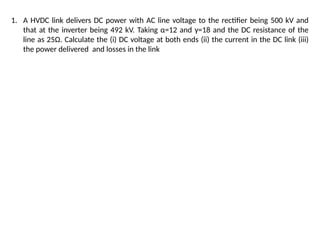
2. A HVDC link delivers DC power with AC line voltage to the rectifier being 500 kV
and that at the inverter being 492 kV. Taking α=12 and γ=18 and the DC
resistance of the line as 25Ω. Calculate the (i) DC voltage at both ends (ii) the
current in the DC link (iii) the power delivered and losses in the link
Problems on HVDC
55.
1. A bipolartwo terminal HVDC link is delivering 800 MW at ±400 kV at the
receiving end. The total losses in the DC circuit are 40 MW. Calculate the
following: (i) Sending end power (ii) Sending end voltage (iii) Power in the
middle of the line (iv) Voltage in the middle of the line (v) Total resistance of the
DC circuit.
56.
1. A HVDClink delivers DC power with AC line voltage to the rectifier being 500 kV and
that at the inverter being 492 kV. Taking α=12 and γ=18 and the DC resistance of the
line as 25Ω. Calculate the (i) DC voltage at both ends (ii) the current in the DC link (iii)
the power delivered and losses in the link

![ADVANTAGES OF HVDC TRANSMISSION
01/24/2026 14
1. Interconnection of systems using long length of cables in particular while crossing sea
water.
2. Interconnection of systems operating at different frequencies (as asynchronous tie).
3. Reduced transmission losses.
4. Rigid control over the magnitude and direction of power flow with easy reversibility of
power flow.
5. Limiting the transfer of fault current.
6. Damping out oscillations and improving the stability margins when embedded in weak
AC systems of low short circuit ratio (SCR). The strength of AC systems connected to the
terminals of DC links is measured in terms of short circuit ratio (SCR). [SCR is defined as
the AC power transfer under short circuit at the converter bus or rated DC power. If SCR
is less than 3, then AC system is said to be weak.]
7. HVDC transmission is most useful in areas requiring crossing of long waterways like
crossing a sea to feed an island through submarine cables. The first major DC
transmission line was established in 1960 in USSR for transmitting power of 750 MW at
±400 kV, over a distance of 500 km. In USA, a DC line of 1360 km length operating at
±400 kV for transmission of bulk power of l440 MW was established in 1970.](https://image.slidesharecdn.com/module67-hvdcsystem-260124083557-4df09882/85/High-Voltage-DC-Engineering-Module-6-7-HVDC-system-14-320.jpg)