Herramientas de ensamble Ingersoll Rand
•
1 like•345 views

The document is a catalog for assembly tools from Ingersoll Rand that includes electric screwdrivers and fastening tools. It provides specifications for various models of electric screwdrivers including torque range, speed, weight and dimensions. It also lists accessories such as balancers and bits that can be used with the screwdrivers. The catalog describes features of the screwdriver models such as adjustable torque control, ergonomic designs, and ESD protection for electronics assembly. It indicates that Ingersoll Rand tools provide precise torque and speed control for assembly applications.

Recommended
Recommended
More Related Content
What's hot
What's hot (20)
Similar to Herramientas de ensamble Ingersoll Rand
Similar to Herramientas de ensamble Ingersoll Rand (20)
More from Almacenes JJ S.A.
More from Almacenes JJ S.A. (20)
Recently uploaded
Recently uploaded (20)
Herramientas de ensamble Ingersoll Rand
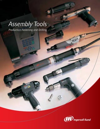
- 1. Assembly Tools Production Fastening and Drilling 1-5.indd 11-5.indd 1 7/2/08 12:52:55 PM7/2/08 12:52:55 PM
- 2. 2 Contents Electric Fastening Tools 6 Electric Screwdrivers 18 DC Electric Nutrunners 30 DC Electric Fixtured Spindles 36 Fixtured Fastening Systems 42 ICS Software 39 DC Electric Controllers 49 Calibration Equipment Air Fastening Tools 55 Pistol Grip Screwdrivers 78 Inline Screwdrivers 94 Angle Air Nutrunners 115 Inline Air Nutrunners 125 Pulse Tools Air Production Drills 140 Pistol Grip Drills 154 Inline Drills 161 Angle Drills 169 Modular Drills Accessories 177 Spring Balancers 180 Torque Reaction Arms & Holders 182 Workstations 183 Spindle Accessories 186 Other Accessories Other Air Tools 172 Air Tappers 174 Air Riveters 175 Electrode Dressers Model Identification Guide ... 187 Reference Guides ................... 191 Index ....................................... 195 1-5.indd 21-5.indd 2 7/2/08 12:52:57 PM7/2/08 12:52:57 PM
- 3. Footer 3 (800) 376-8665 • irtools.com 3 Technical Symbols Fixtured fastening systems Voltage Spindle accessories Drilling Tapping Riveting Spring balancers Pistol grip fastening tools Pistol grip drills Straight fastening tools Torque range with light clutch spring Max. air consumption Piston stroke Bit holder or Square drive Square drive or bit holder Floating spindle stroke Spindle thread Square drive or bit holder Torque range with medium clutch spring Torque range with heavy clutch spring Max. free speed Bolt capacity Stall torque Max chuck/ collet capacity or bit holder Blows per minute Rivet set shank diameter Tool weight Straight drills Angle fastening tools Angle drills Fixtured fastening tools Torque control system Reversible models Non-reversible models Torque range For ease of use, specification tables frequently use symbols in column headings. Please reference the chart below for exact descriptions. Tool length Tool length Tool length Tool length Tool length 1-5.indd 31-5.indd 3 7/2/08 12:53:08 PM7/2/08 12:53:08 PM
- 4. 4 Technical Symbols (Cont.) Side-to- center distance Operation and maintenance manual Side-to- center distance Side-to- center distance Side-to- center distance Calibration equipment Electrode dressers Working stations Side-to- center distance Angle head height Angle head height Nominal load capacity Standard height of lift 1/4” hex quick change 1/4” hex bit holder 1/4” hex insert bit holder 1/4” hex bit holder (requires bit guide or finder) Square drive Sound level Tool air inlet connection Hose min. internal diameter Rated power Size Spindle length Bore Spindle length Number of tools controlled Side-to- center distance Tool length Parts manual ICS software Tool length Maintenance information manual Tool length Product information manual Ø SWL Other accessories Torque reaction arms & holders 1-5.indd 41-5.indd 4 7/2/08 12:53:24 PM7/2/08 12:53:24 PM
- 5. Footer 5 (800) 376-8665 • irtools.com 5 Electric Fastening Tools Ingersoll Rand’s full line of Electric Fastening Tools delivers the ultimate combination of accuracy, durability, and ergonomics to maximize your assembly line’s productivity. The World-Class QE & QM Series of handheld and fixtured DC electric tools, coupled with ICD & M Controllers and Software, offer state of the art closed-loop transducerized control for your most critical applications. For other applications, our high quality family of mechanical clutch electric screwdrivers offers an economical alternative to closed-loop control. Regardless of the complexity of your requirements, you can trust Ingersoll Rand to deliver the right solution to meet your needs. 6Electric Screwdrivers 18DC Electric Nutrunners 30DC Electric Fixtured Spindles 36Fixtured Fastening Systems 42ICS Software 39DC Electric Controllers 49Calibration Equipment 1-5.indd 51-5.indd 5 7/2/08 12:53:35 PM7/2/08 12:53:35 PM
- 6. 6 Electric Screwdriver Torque Selection Guide 0 0.25 Nm 0.50 Nm 0.75 Nm 1.00 Nm 1.25 Nm 1.50 Nm Referral Model ▼ ▼ ▼ ▼ ▼ ▼ ▼ page ELM0110N 7 EL0109B 9 ELM0107N 7 ELM0306N 7 EL0410BC-SS-ESD 8 EL0510BC-SS-ESD 8 EL0410B 9 ES45T 10 EL0807BC-SS-ESD 8 ES50T 10 EL1007BC-ESD 8 EL1007B 9 DC Screwdrivers 0 0.5 Nm 1.0 Nm 1.5 Nm 2.0 Nm 2.5 Nm 3.0 Nm 3.5 Nm 4.0 Nm 4.5 Nm Referral Model ▼ ▼ ▼ ▼ ▼ ▼ ▼ ▼ ▼ ▼ page EP1520N 12 EP1510N 12 ES90P 13 ES60P 13 ES80P 13 EP2612N 12 EP2607N 12 EP2603N 12 ES70P 13 EPB2612N 11 EPB2620N 11 ET4007N 12 ES100T 13 AC Screwdrivers 0 1.0 Nm 2.0 Nm 3.0 Nm 4.0 Nm 5.0 Nm 6.0 Nm 7.0 Nm Referral Model ▼ ▼ ▼ ▼ ▼ ▼ ▼ ▼ page ES90T1S5 15 EL1510N1S5 14 ES90T2S3 15 EL1510N2S3 14 ES60T2S3 15 EL2612N1S5 14 ES70T1S5 15 ES70T2S3 15 EL2612N2S3 14 ES100T2S3 15 ET4007N2S3 14 Angle Head Screwdrivers 6-19.indd 66-19.indd 6 7/2/08 12:54:05 PM7/2/08 12:54:05 PM
- 7. Footer 7 (800) 376-8665 • irtools.com 7 ELM0107N ECM24N Electric Screwdrivers Inline Service and Accessories Accessories: Balancer, see page 177 Shaker box, see page 16 Bits, see page 17 Micro Electric Screwdrivers ESD protection in an ergonomic space-saving package. Features • Torque Range: 0.18 – 3.5 in-lbs (0.02 – 0.40 Nm) • Speeds: 600 – 1,000 rpm • 24 V DC from controller (ECM24N) • Electro-static discharge (ESD) models offer added protection for sensitive electronic assembly applications • Extremely lightweight and compact ergonomic design • Variable speed and soft-start features built into controller • Detachable 1.5 m cable, hanger bail, and two bits included • Recommended for low-torque applications requiring additional ESD protection along with precise torque and speed control Manuals: 45549169 45549144 45549177 Controller Manuals: 45549193 45549185 45549201 Adjustable Shut-Off Clutch Soft Speed ESD Start Adjust Control Model Input Voltage Output Voltage lb (kg) in (mm) CONTROLLER ECM24N 115 V AC 24 V DC 1.98 (0.90) 5.9” x 3.6” x 2.1” (150 x 91 x 52) YES YES YES Controller Required Model V in-lbs (Nm) in-lbs (Nm) rpm lb (kg) in (mm) in (mm) INLINE LEVER START ELM0107N 24 V DC 0.18 – 0.62 (0.02 – 0.07) 0.35 – 1.77 (0.04 – 0.20) 750 0.51 (0.23) 6.52” (165.5) 0.16” (4.0) ECM24N ELM0110N 24 V DC 0.18 – 0.62 (0.02 – 0.07) 0.35 – 1.77 (0.04 – 0.20) 1,000 0.51 (0.23) 6.52” (165.5) 0.16” (4.0) ECM24N ELM0306N 24 V DC 1.33 – 3.54 (0.15 – 0.40) – 600 0.51 (0.23) 6.52” (165.5) 0.16” (4.0) ECM24N 6-19.indd 76-19.indd 7 7/2/08 12:54:09 PM7/2/08 12:54:09 PM
- 8. 8 Service and Accessories Accessories: Balancer, see page 177 Shaker box, see page 16 Bits, see page 17 Low-Torque Versatec ESD ESD protection in an award-winning ergonomic package. Features • Torque Range: 1.7 – 10.4 in-lbs (0.19 – 1.2 Nm) • Speeds: 500 – 1,000 rpm • 24 V DC from ESD controller (EC24N-ESD) • Electro-static discharge (ESD) models offer added protection for sensitive electronic assembly applications • Variable speed and soft-start features built into controller • Lightweight, compact design • Clean room-rated • Vacuum pickup ready • Soft stop models minimize failures to sensitive equipment by limiting the motor inertia as the clutch begins to shut off • Recommended for low-torque applications requiring additional ESD protection along with precise torque and speed control Manuals: 16574683 16578692 16575367 Controller Manuals: 45532066 45532041 45532058 Controller Required Model V in-lbs (Nm) rpm lb (kg) in (mm) in (mm) LEVER START ESD ONLY MODEL EL1007BC-ESD 24 V DC 1.7 – 10.4 (0.19 - 1.2) 500 – 700 0.77 (0.35) 10.5” (267) 1/4” EC24N-ESD LEVER START SOFT STOP ESD MODELS EL0410BC-SS-ESD 24 V DC 1.7 – 3.5 (0.2 – 0.4) 700 – 1000 0.88 (0.4) 10.5” (267) 0.16” (4.0) EC24N-ESD EL0510BC-SS-ESD 24 V DC 2.2 – 4.8 (0.2 – 0.5) 700 – 1000 0.88 (0.4) 10.5” (267) 0.16” (4.0) EC24N-ESD EL0807BC-SS-ESD 24 V DC 3.9 – 8.2 (0.4 – 0.9) 500 – 700 0.88 (0.4) 10.5” (267) 0.16” (4.0) EC24N-ESD EL1007BC-SS-ESD 24 V DC 4.8 – 10.4 (0.5 – 1.2) 700 – 1000 0.88 (0.4) 10.5” (267) 0.16” (4.0) EC24N-ESD EL1007B Adjustable Shut-Off Clutch Soft Speed ESD Start Adjust Control Model Input Voltage Output Voltage lb (kg) in (mm) CONTROLLER EC24N-ESD 115 V AC 24 V DC 5.1 (2.31) 10.5” x 3.3” x 4.1” (267 x 83 x 104) YES YES YES Electric Screwdrivers Inline 6-19.indd 86-19.indd 8 7/2/08 12:54:14 PM7/2/08 12:54:14 PM
- 9. Footer 9 (800) 376-8665 • irtools.com 9 Controller Required Model V in-lbs (Nm) rpm lb (kg) in (mm) in (mm) INLINE LEVER START EL0109B 24 V DC 0.26 – 1.30 (0.03 – 0.15) 650 – 950 0.7 (0.32) 9.25” (235) 0.16” (4.06) EC24N EL0410B 24 V DC 0.44 – 4.79 (0.05 – 0.54) 750 – 1000 0.8 (0.32) 9.25” (235) 0.25” (6.35) EC24N EL1007B* 24 V DC 0.5 – 10.44 (0.06 – 1.2) 500 – 700 0.8 (0.32) 9.25” (235) 0.25” (6.35) EC24N INLINE LEVER START CLEAN ROOM EL0410BC 24 V DC 0.44 – 4.79 (0.05 – 0.54) 750 – 1000 0.8 (0.32) 9.25” (235) 0.25” (6.35) EC24N EL1007BC* 24 V DC 0.5 – 10.44 (0.06 – 1.2) 500 – 700 0.8 (0.32) 9.25” (235) 0.25” (6.35) EC24N Service and Accessories Accessories: Balancer, see page 177 Shaker box, see page 16 Bits, see page 17 Low-Torque Versatec Sets the standards for ergonomics and operator convenience. Features • Torque Range: 0.26 – 10.4 in-lbs (0.03 – 1.2 Nm) • Speeds: 500 – 1,000 rpm • 24 V DC from controller (EC24N) • Ergonomic package features contoured soft-touch grip, two-finger lever actuation, and easy forward reverse control providing the ultimate in operator comfort and productivity • Variable speed and soft-start features built into controller • Lightweight, compact design • Externally adjustable torque control • Clean room models available without soft-touch grip • Two bits, 1.5 m cable, and hanger bail included • Recommended for low-torque applications requiring precise torque and speed control Manuals: 45530128 45527595 45530136 Controller Manuals: 45532066 45532041 45532058 Adjustable Shut-Off Clutch *Two clutch springs are furnished to cover torque range. Tool is shipped with heavier clutch spring installed. Soft Speed ESD Start Adjust Control Model Input Voltage Output Voltage lb (kg) in (mm) CONTROLLER EC24N 115 V AC 24 V DC 5.1 (2.31) 10.5” x 3.3” x 4.1” (267 x 83 x 104) YES YES NO 6-19.indd 96-19.indd 9 7/2/08 12:54:18 PM7/2/08 12:54:18 PM
- 10. 10 Service and Accessories Accessories: Balancer, see page 177 Shaker box, see page 16 Bits, see page 17 Low-Torque ES Series Proven performance in an economical package. Features • Torque Range: 0.4 – 9.0 in-lbs (0.05 – 1.0 Nm) • Speeds: 500 – 900 rpm • 24 V DC from controller (ESCB50) • Precise torque control for more efficient and accurate production • Variable speed and soft-start features built into controller • Externally adjustable torque control • Clean room models available • Two bits, 1.5 m cable, and hanger bail included • Recommended for low-torque applications requiring precise torque and speed control Manuals: 45527777 45527702 45527801 Controller Manuals: 45532090 45532074 45532082 Controller Required Model V in-lbs (Nm) in-lbs (Nm) rpm lb (kg) in (mm) in (mm) INLINE LEVER START ES45T 24 V DC 0.5 – 4.7 (0.06 – 0.53) 1.7 – 6.0 (0.19 – 0.68) 600 – 900 0.75 (0.34) 8.87” (225) 0.25” (6.35) ESCB50 ES50T 24 V DC 0.4 – 4.7 (0.05 – 0.53) 2.0 – 9.0 (0.23 – 1.02) 500 – 650 0.75 (0.34) 8.88” (226) 0.25” (6.35) ESCB50 INLINE CLEAN ROOM LEVER START ES50TC 24 V DC 0.4 – 4.7 (0.05 – 0.53) 2.0 – 9.0 (0.23 – 1.02) 500 – 650 0.88 (0.40) 10.50” (267) 0.25” (6.35) ESCB50 ES50T & ESCB50 Adjustable Shut-Off Clutch Soft Speed Start Adjust Model Input Voltage Output Voltage lb (kg) in (mm) CONTROLLER ESCB50 115 V AC 24 V DC 4.4 (1.9) 6.8” x 5.8” x 4.3” (171 x 146 x 108) YES YES Electric Screwdrivers Inline 6-19.indd 106-19.indd 10 7/2/08 12:54:23 PM7/2/08 12:54:23 PM
- 11. Footer 11 (800) 376-8665 • irtools.com 11 Service and Accessories Accessories: Balancer, see page 177 Shaker box, see page 16 Bits, see page 17 Pistol grip handle: DLW2100TP High-Torque Brushless Brushless design provides accuracy and increased durability. Features • Torque Range: 3.5 – 26.5 in-lbs (0.4 – 3.0 Nm) • Speeds: 1,200 – 2,000 rpm • 115 V AC plug in with integral 3 m cable • Excellent accuracy and durability resulting from improved clutch and brushless motor design • Wide torque range allows expanded application coverage from a single tool • Ergonomic soft-touch grip improves operator comfort • RoHS-compliant • Bit, hanger bail, and low-torque spring included • Recommended for higher duty cycle applications where precise torque control is required Manuals: 45549128 45549110 45549136 Model V in-lbs (Nm) in-lbs (Nm) rpm lb (kg) in (mm) in (mm) INLINE PUSH-TO-START EPB2612N 115 V AC 3.54 – 14.16 (0.4 – 1.6) 10.62 – 26.55 (1.2 – 3.0) 1,200 1.54 (0.7) 10.9” (276) 0.25” (6.4) EPB2620N 115 V AC 3.54 – 14.16 (0.4 – 1.6) 10.62 – 26.55 (1.2 – 3.0) 2,000 1.54 (0.7) 10.9” (276) 0.25” (6.4) INLINE LEVER START ELB2612N 115 V AC 3.54 – 14.16 (0.4 – 1.6) 10.62 – 26.55 (1.2 – 3.0) 1,200 1.54 (0.7) 10.8” (274) 0.25” (6.4) ELB2620N 115 V AC 3.54 – 14.16 (0.4 – 1.6) 10.62 – 26.55 (1.2 – 3.0) 2,000 1.54 (0.7) 10.8” (274) 0.25” (6.4) ELB2612N ELB2620N Adjustable Shut-Off Clutch 6-19.indd 116-19.indd 11 7/2/08 12:54:27 PM7/2/08 12:54:27 PM
- 12. 12 Service and Accessories Accessories: Balancer, see page 177 Shaker box, see page 16 Bits, see page 17 Pistol grip handle; EP4007N-48 Torque adjusting wrench, see page 16 High-Torque Versatec Sets the standards for ergonomics and operator convenience. Features • Torque Range: 5.0 – 40.0 in-lbs (0.6 – 4.5 Nm) • Speeds: 300 – 2,000 rpm • 115 V AC plug in with detachable 8 foot cable • Ergonomic package features contoured soft-touch grip, two-finger lever actuation, and easy forward reverse control providing the ultimate in operator comfort and productivity • Removable contoured flange and torque adjustment cover protects torque setting while giving instant visible confirmation in readout window • Brush replacement light signals when maintenance is required • Dual position cord allows 90 degree connector rotation for optimal cable routing • Two bits, two brushes, and hanger bail included • Recommended for applications where precise torque control is required Manuals: 45530102 45527579 45530110 EP4007N Adjustable Shut-Off Clutch Model V in-lbs (Nm) rpm lb (kg) in (mm) in (mm) INLINE PUSH-TO-START EP1520N 115 V AC 5.0 – 15.0 (0.6 – 1.7) 2,000 1.6 (0.73) 11.25” (286) 0.25” (6.35) EP1510N 115 V AC 5.0 – 15.0 (0.6 – 1.7) 1,000 1.6 (0.73) 11.25” (286) 0.25” (6.35) EP2612N 115 V AC 11.0 – 26.0 (1.2 – 2.9) 1,200 1.6 (0.73) 11.25” (286) 0.25” (6.35) EP2607N 115 V AC 11.0 – 26.0 (1.2 – 2.9) 700 1.6 (0.73) 11.25” (286) 0.25” (6.35) EP2603N 115 V AC 11.0 – 26.0 (1.2 – 2.9) 300 1.6 (0.73) 11.25” (286) 0.25” (6.35) INLINE LEVER START EL1520N 115 V AC 5.0 – 15.0 (0.6 – 1.7) 2,000 1.63 (0.74) 11.25” (286) 0.25” (6.35) EL1510N 115 V AC 5.0 – 15.0 (0.6 – 1.7) 1,000 1.63 (0.74) 11.25” (286) 0.25” (6.35) EL2612N 115 V AC 11.0 – 26.0 (1.2 – 2.9) 1,200 1.63 (0.74) 11.25” (286) 0.25” (6.35) EL2607N 115 V AC 11.0 – 26.0 (1.2 – 2.9) 700 1.63 (0.74) 11.25” (286) 0.25” (6.35) EL2603N 115 V AC 11.0 – 26.0 (1.2 – 2.9) 300 1.63 (0.74) 11.25” (286) 0.25” (6.35) TRIGGER START WITH PISTOL ATTACHMENT ET4007N 115 V AC 18.0 – 40.0 (2.0 – 4.5) 700 1.83 (0.83) 11.25” (286) 0.25” (6.35) PUSH-TO-START WITH PISTOL ATTACHMENT EP4007N 115 V AC 18.0 – 40.0 (2.0 – 4.5) 700 1.83 (0.83) 11.25” (286) 0.25” (6.35) Electric Screwdrivers Inline / Pistol 6-19.indd 126-19.indd 12 7/2/08 12:54:32 PM7/2/08 12:54:32 PM
- 13. Footer 13 (800) 376-8665 • irtools.com 13 Service and Accessories Accessories: Balancer, see page 177 Shaker box, see page 16 Bits, see page 17 Pistol grip handle: DLW2100TP High-Torque ES Series Proven performance in an economical package. Features • Torque Range: 4.0 – 40.0 in-lbs (0.5 – 4.5 Nm) • Speeds: 400 – 2,000 rpm • 115 V AC plug in with integral 3 m cable • Precise torque control for more efficient and accurate production • Two bits, two brushes, and hanger bail included • Recommended for applications where precise torque control is required Manuals: 45527751 45527611 45527785 ES60T ES100T Adjustable Shut-Off Clutch Model V in-lbs (Nm) rpm lb (kg) in (mm) in (mm) INLINE PUSH-TO-START ES90P 115 V AC 4.4 – 16.0 (0.5 – 1.8) 2,000 1.50 (0.68) 10.00” (254) 0.25” (6.35) ES60P 115 V AC 4.4 – 17.0 (0.5 – 1.9) 1,000 1.50 (0.68) 10.00” (254) 0.25” (6.35) ES80P 115 V AC 12.0 – 24.0 (1.4 – 2.7) 1,200 1.50 (0.68) 10.00” (254) 0.25” (6.35) ES70P 115 V AC 10.0 – 26.0 (1.1 – 2.9) 700 1.50 (0.68) 10.00” (254) 0.25” (6.35) INLINE LEVER START ES90T 115 V AC 4.4 – 16.0 (0.5 – 1.8) 2,000 1.53 (0.69) 10.00” (254) 0.25” (6.35) ES60T 115 V AC 4.4 – 17.0 (0.5 – 1.9) 1,000 1.53 (0.69) 10.00” (254) 0.25” (6.35) ES70T 115 V AC 10.0 – 26.0 (1.1 – 2.9) 700 1.53 (0.69) 10.00” (254) 0.25” (6.35) TRIGGER START WITH PISTOL ATTACHMENT ES100T 115 V AC 15.0 – 40.0 (1.9 – 4.5) 400 1.68 (0.76) 10.00” (254) 0.25” (6.35) PUSH-TO-START WITH PISTOL ATTACHMENT ES100P 115 V AC 15.0 – 40.0 (1.9 – 4.5) 400 1.65 (0.75) 10.00” (254) 0.25” (6.35) 6-19.indd 136-19.indd 13 7/2/08 12:54:36 PM7/2/08 12:54:36 PM
- 14. 14 Electric Screwdrivers Angle Service and Accessories Accessories: Balancer, see page 177 Pistol grip handle: EP4007N-48 Sockets, see form # IR-0506-016 High-Torque Versatec Sets the standards for ergonomics and operator convenience. Features • Torque Range: 5.0 – 60.0 in-lbs (0.6 – 6.8 Nm) • Speeds: 450 – 1,850 rpm • 115 V AC plug in with detachable 8 foot cable • Ergonomic package features contoured soft-touch grip, two-finger lever actuation, and easy forward reverse control providing the ultimate in operator comfort and productivity • Removable contoured flange and torque adjustment cover protects torque setting while giving instant visible confirmation in readout window • Brush replacement light signals when maintenance is required • Dual-position cord allows optimal cable routing • Small angleheads designed for close quarter applications • Angleheads rotate 360 degrees • Two bits, two brushes, and hanger bail included • Recommended for applications where precise torque control is required Manuals: 45530102 45527579 45530110 Adjustable Shut-Off Clutch EL1510N2S5 Model V in-lbs (Nm) rpm lb (kg) in (mm) in (mm) in (mm) in LEVER START LARGE ANGLE HEAD EL1510N2S5 115 V AC 8 – 23 (0.9 – 2.6) 650 2.20 (1.00) 17.64” (448) 0.52” (13.21) 1.73” (43.94) 1/4” EL2612N2S5 115 V AC 17 – 40 (1.9 – 4.5) 800 2.20 (1.00) 17.64” (448) 0.52” (13.21) 1.73” (43.94) 1/4” ET4007N2S5 115 V AC 27 – 60 (3.0 – 6.8) 450 2.20 (1.00) 17.64” (448) 0.52” (13.21) 1.73” (43.94) 1/4” EL1510N2S3 115 V AC 8 – 23 (0.9 – 2.6) 650 2.20 (1.00) 17.64” (448) 0.52” (13.21) 1.73” (43.94) 1/4” EL2612N2S3 115 V AC 17 – 40 (1.9 – 4.5) 800 2.20 (1.00) 17.64” (448) 0.52” (13.21) 1.73” (43.94) 1/4” ET4007N2S3 115 V AC 27 – 60 (3.0 – 6.8) 450 2.20 (1.00) 17.64” (448) 0.52” (13.21) 1.73” (43.94) 1/4” LEVER START SMALL ANGLE HEAD EL1520N1S5* 115 V AC 5 – 15 (0.6 – 1.7) 1,850 2.00 (0.91) 17.45” (443) 0.33” (8.38) 1.47” (37.34) 1/4” EL1510N1S5* 115 V AC 5 – 15 (0.6 – 1.7) 950 2.00 (0.91) 17.45” (443) 0.33” (8.38) 1.47” (37.34) 1/4” EL2612N1S5* 115 V AC 11 – 26 (1.2 – 2.9) 1,100 2.00 (0.91) 17.45” (443) 0.33” (8.38) 1.47” (37.34) 1/4” *This head is designed for close-quarter applications. Not intended for extensive counterclockwise use. Angle heads can rotate 360 degrees for application adjustment. Torque output will vary with application. 6-19.indd 146-19.indd 14 7/2/08 12:54:40 PM7/2/08 12:54:40 PM
- 15. Footer 15 (800) 376-8665 • irtools.com 15 Service and Accessories Accessories: Balancer, see page 177 Pistol grip handle; EP4007N-48 Sockets, see form # IR-0506-016 High-Torque ES Series Proven performance in an economical package. Features • Torque Range: 4.0 – 56.0 in-lbs (0.45 – 6.3 Nm) • Speeds: 250 – 1,850 rpm • 115 V AC plug in with integral 3 m cable • Precise torque control for more efficient and accurate production • Small angleheads designed for close-quarter applications • Angleheads rotate 360 degrees • Two bits, two brushes, and hanger bail included • Recommended for applications where precise torque control is required Manuals: 45527769 45527678 ES70T2S3 Adjustable Shut-Off Clutch Model V in-lbs (Nm) rpm lb (kg) in (mm) in (mm) in (mm) in LEVER START LARGE ANGLE HEAD ES90T2S3 115 VAC 6 – 19 (0.68 – 2.2) 1,300 2.1 (0.95) 16.89” (429) 0.52” (13.21) 1.99” (50.55) 1/4” ES60T2S3 115 VAC 6 – 23 (0.68 – 2.6) 650 2.1 (0.95) 16.89” (429) 0.52” (13.21) 1.99” (50.55) 1/4” ES70T2S3 115 VAC 11 – 36 (1.2 – 4.1) 450 2.1 (0.95) 16.89” (429) 0.52” (13.21) 1.99” (50.55) 1/4” ES100T2S3 115 VAC 14 – 56 (1.6 – 6.3) 250 2.1 (0.95) 16.89” (429) 0.52” (13.21) 1.99” (50.55) 1/4” ES90T2S5 115 VAC 6 – 19 (0.68 – 2.2) 1,300 2.1 (0.95) 16.89” (429) 0.52” (13.21) 1.73” (43.94) 1/4” ES60T2S5 115 VAC 6 – 23 (0.68 – 2.6) 650 2.1 (0.95) 16.89” (429) 0.52” (13.21) 1.73” (43.94) 1/4” ES70T2S5 115 VAC 11 – 36 (1.2 – 4.1) 450 2.1 (0.95) 16.89” (429) 0.52” (13.21) 1.73” (43.94) 1/4” ES100T2S5 115 VAC 14 – 56 (1.6 – 6.3) 250 2.1 (0.95) 16.89” (429) 0.52” (13.21) 1.73” (43.94) 1/4” LEVER START SMALL ANGLE HEAD ES90T1S5 115 VAC 4 – 14 (0.45 – 1.6) 1,850 1.9 (0.86) 16.70” (424) 0.33” (8.38) 1.47” (37.34) 1/4” ES60T1S5 115 VAC 4 – 17 (0.45 – 1.9) 950 1.9 (0.86) 16.70” (424) 0.33” (8.38) 1.47” (37.34) 1/4” ES70T1S5 115 VAC 8 – 26 (0.90 – 2.9) 650 1.9 (0.86) 16.70” (424) 0.33” (8.38) 1.47” (37.34) 1/4” 6-19.indd 156-19.indd 15 7/2/08 12:54:44 PM7/2/08 12:54:44 PM
- 16. 16 Torque Adjustment Covers Suspension Bails Power and Extension Cords Other Accessories Angle Head Conversion Pistol Attachment Electric Screwdrivers Accessories Part Number Description For Use With ES60T-675 Torque Adjustment Cover ES60, ES70, ES80, ES90, ES100 EL0410BC-46 Torque Adjustment Cover Low-Torque VersaTec EL0410BC-46-ESD Torque Adjustment Cover Low-Torque VersaTec - ESD Part Number Description For Use With EP4007N-365 Vertical Suspension Bail High-Torque VersaTec EP4007N-366 Horizontal Suspension Bail High-Torque VersaTec EL0109B-365 Vertical Suspension Bail Low-Torque VersaTec DAA40-A366 Horizontal Hanger Electric angle screwdrivers Part Number Description For Use With EL0109B-239 Power Cord Assembly High-Torque VersaTec ES40T-249 Power Cord Assembly Low-Torque ES EP4007N-239-C6A 6’ Coiled Extension Cord High-Torque VersaTec EP4007N-239-8A 8’ Coiled Extension Cord High-Torque VersaTec EP4007N-239-12A 12’ Coiled Extension Cord High-Torque VersaTec EP4007N-239-25 25’ Coiled Extension Cord High-Torque VersaTec ES40T-249-2 6.5’ Extension Cord Low-Torque ES and VersaTec Component Part Number Description A 3RL23 1/4” Quick Change A 3RL25 1/4” Square Drive B EL4007N2S5-AHC Coupling Nut C ET4007N2S5-580 Clutch Cover Part Number Description For Use With EP4007N-48 Attachable Pistol High-Torque Grip handle VersaTec DLW2100TP Attachable Pistol ES60, ES70 ES80, Grip handle ES90, EPB, ELB Part Number Description Shape For Use With EP4007N-516 Torque Adjusting N/A VersaTec Models Wrench DLW3402 Plastic Screw 5-1/2” x 3-7/8” Screw sizes Shaker Box 0 – 2 mm (0.07” – 0.08”) DLW3602 Plastic Screw 5-1/2” x 3-7/8” Screw sizes Shaker Box 1 – 4 mm (0.08” – 0.11”) DLW3802 Plastic Screw 6-11/16” x 4-7/8” Screw sizes Shaker Box 3 – 8 mm (0.12” – 0.16”) 6-19.indd 166-19.indd 16 7/2/08 12:54:48 PM7/2/08 12:54:48 PM
- 17. Footer 17 (800) 376-8665 • irtools.com 17 Vacuum Pick-Up Sleeves Complementing “A” Inside “B” Outside Bit Part Diameter Diameter Part Number Number in (mm) in (mm) DLS2120 DLB2122-10 0.079” (2.0) 0.138” (3.5) DLS2122 DLB2122-10 0.098” (2.5) 0.138” (3.5) DLS2123 DLB2122-10 0.106” (2.7) 0.138” (3.5) DLS2124 DLB2122-10 0.122” (3.1) 0.138” (3.5) DLS2125 DLB2124-10 0.130” (3.3) 0.177” (4.5) DLS2126 DLB2124-10 0.138” (3.5) 0.177” (4.5) DLS2127 DLB2124-10 0.146” (3.7) 0.177” (4.5) DLS2128 DLB2126-10 0.158” (4.0) 0.177” (4.5) DLS2129 DLB2126-10 0.165” (4.2) 0.212” (5.5) DLS2130 DLB2126-10 0.177” (4.5) 0.212” (5.5) DLS2131 DLB2128-10, 0.185” (4.7) 0.212” (5.5) DLB2130-10, XP161, XRP161 DLS2132 DLB2128-10, 0.201” (5.1) 0.212” (5.5) DLB2130-10, XP161, XRP161 DLS2133 DLB2128-10, 0.209” (5.3) 0.256” (6.5) DLB2130-10, XP161, XRP161 DLS2134 DLB2128-10, 0.221” (5.6) 0.256” (6.5) DLB2130-10, XP161, XRP161 EL0410BC-53 DLB2128-10, 0.240” (6.1) 0.276” (7.0) DLB2130-10, XP161, XRP161 L Phillips Bits “A” “L” Screw Point Diameter Length Size Part Number Size in (mm) in Range Quantity DLB2120-10 0 0.071” (1.8) 1.7” 0 – 1 10 DLB2121-10 0 0.071” (1.8) 2.5” 0 – 1 10 DLB2122-10 0 0.079” (2.0) 1.7” 00 – 0 10 DLB2123-10 0 0.079” (2.0) 2.5” 00 – 0 10 DLB2124-10 0 0.098” (2.5) 1.7” 0 – 1 10 DLB2125-10 0 0.098” (2.5) 2.5” 0 – 1 10 DLB2126-10 1 0.118” (3.0) 1.7” 2 – 4 10 DLB2127-10 1 0.118” (3.0) 2.5” 2 – 4 10 DLB2128-10 1 0.157” (4.0) 1.7” 2 – 4 10 DLB2129-10 1 0.157” (4.0) 2.5” 2 – 4 10 DLB2130-10 2 0.157” (4.0) 1.7” 5 – 10 10 DLB2131-10 2 0.157” (4.0) 2.5” 5 – 10 10 DLB2132-10 3 0.236” (6.0) 1.7” 10 – 1/4 10 L Slot Bits “T” “A” “L” Screw Size Diameter Length Size Part Number in in (mm) in Range Quantity DLB2220-10 0.012 0.079” (2.0) 1.7” 00 – 0 10 DLB2221-10 0.012 0.098” (2.5) 1.7” 00 – 0 10 DLB2222-10 0.016 0.117” (3.0) 1.7” 0 – 2 10 DLB2223-10 0.02 0.157” (4.0) 1.7” 2 – 4 10 DLB2224-10 0.026 0.197” (5.0) 1.7” 3 – 5 10L Hexagon, Male and Female “A” “L” Screw Hex Size Length Use Part Number Size in (mm) in Diagram Quantity DLB2321-10 0.12 0.059” (1.5) 1.7” Male 10 DLB2322-10 0.16 0.079” (2.0) 1.7” Male 10 DLB2323-10 0.24 0.118” (3.0) 1.7” Male 10 DLB2324-10 0.31 0.157” (4.0) 1.7” Male 10 DLB2420-10 N/A 0.091” (2.3) 1.7” Female 10 DLB2421-10 N/A 0.098” (2.5) 1.7” Female 10 DLB2422-10 N/A 0.118” (3.0) 1.7” Female 10 DLB2423-10 0.08 0.157” (4.0) 1.7” Female 10 DLB2424-10 0.09 0.177” (4.5) 1.7” Female 10 DLB2425-10 0.1 0.197” (5.0) 1.7” Female 10 DLB2426-10 0.12 0.217” (5.5) 1.7” Female 10 L L Part Number Description For Use With DLW-4100 Slotted Bit Holder EL0109B / “Micro” / SS-ESD Insert Bit Holders 6-19.indd 17 7/10/08 8:02:28 AM
- 18. 18 DC Electric Nutrunners Torque Selection Guide Inline Push-to-Start Inline 0 Nm 20 Nm 40 Nm 60 Nm 80 Nm 100 Nm 150 Nm 200 Nm 250 Nm Referral Model ▼ ▼ ▼ ▼ ▼ ▼ ▼ ▼ ▼ page QE4ST010B… 22 QE4ST015B… 22 QE4ST020B… 23 QE6ST020F… 24 QE4ST025B… 23 QE6ST028F… 24 QE6ST033F… 24 QE6ST050F… 24 QE8ST055F… 25 QE8ST070F… 25 QE8ST090F… 25 QE8ST150F… 25 QE8ST230F… 25 Angle 0 Nm 20 Nm 40 Nm 60 Nm 80 Nm 100 Nm 200 Nm 300 Nm 400 Nm Referral Model ▼ ▼ ▼ ▼ ▼ ▼ ▼ ▼ ▼ page QE4AT013P… 28 QE4AT020P… 28 QE4AT027P… 28 QE6AT030P… 29 QE4AT034P… 28 QE6AT040P… 29 QE6AT055P… 29 QE8AT065P… 29 QE8AT070P… 29 QE6AT080P… 29 QE8AT090P… 29 QE8AT115P… 29 QE8AT150P… 29 QE8AT225P… 29 QE8AT400P… 29 0 Nm 5 Nm 10 Nm 15 Nm 20 Nm 25 Nm Referral Model ▼ ▼ ▼ ▼ ▼ ▼ page QE4TS010R11… 19 QE4TS015R11… 19 QE4TS020R11… 19 QE4TS025R11… 19 Pistol Grip 0 Nm 5 Nm 10 Nm 15 Nm 20 Nm 25 Nm Referral Model ▼ ▼ ▼ ▼ ▼ ▼ page QE4PT010P10… 20 QE4PT015P10… 20 QE4PT020P10… 20 QE4PT025P10… 20 0 50 Nm 100 Nm 150 Nm 200 Nm Referral Model ▼ ▼ ▼ ▼ ▼ page QE6ZC020… 26 QE6ZC028… 26 QE6ZC033… 26 QE6ZC050… 26 QE8ZC055… 27 QE8ZC070… 27 QE8ZC090… 27 QE8ZC150… 27 Inline Offset 6-19.indd 186-19.indd 18 7/2/08 12:54:54 PM7/2/08 12:54:54 PM
- 19. Footer 19 (800) 376-8665 • irtools.com 19 DC Electric Nutrunners Push-to-Start Service and Accessories Accessories: Reaction bar kit: GEPTS15-K48 Torque arms, see page 180 Cable, see page 47 ICD & M controllers, see page 39 QE4TS010R11Q04 QE4 Push-to-Start Inline Offering accurate, high-speed, one-handed operation, this tool is activated when the operator presses down on the fastener. This eliminates the need for a lever, saving time and effort. The tool’s unique clevis attachment allows for easy attachment to torque arms while offering the operator optimal hand positioning and workpiece visibility. Features • Torque Range: 0.75 – 18.3 ft-lbs (1 – 25 Nm) • Speeds: Adjustable to 1820 rpm • True closed-loop transducerized control provides exceptional accuracy • Advanced tightening strategies and data and process communications • Compact, high-speed, easily accessible controls • Non-contacting switches, heavy-duty gear train, and DC brushless motor provide exceptional durability • TactAlert provides positive feedback to the operator without distracting from the task • Preventive maintenance alerts • Comfortable ergonomic grip • High-temperature motor protection • Easy-to-use reverse ring • Bright LEDs provide visible status indicators Manuals: 16574451 19576951 16575151 Model ft-lbs (Nm) rpm lbs (kg) in (mm) in (mm) in INLINE PUSH-TO-START QE4TS010R11Q04 0.75 – 7.4 (1 – 10) 1,820 2.6 (1.2) 14.2” (363) 0.98” (25) 1/4” QE4TS010R11S04 0.75 – 7.4 (1 – 10) 1,820 2.6 (1.2) 13.4” (343) 0.98” (25) 1/4” QE4TS010R11S06 0.75 – 7.4 (1 – 10) 1,820 2.6 (1.2) 13.4” (343) 0.98” (25) 3/8” QE4TS015R11Q04 1.1 – 11.0 (1.5 – 15) 1,220 2.6 (1.2) 14.2” (363) 0.98” (25) 1/4” QE4TS015R11S04 1.1 – 11.0 (1.5 – 15) 1,220 2.6 (1.2) 13.4” (343) 0.98” (25) 1/4” QE4TS015R11S06 1.1 – 11.0 (1.5 – 15) 1,220 2.6 (1.2) 13.4” (343) 0.98” (25) 3/8” QE4TS020R11S06 1.5 – 14.7 (2 – 20) 900 2.6 (1.2) 13.4” (343) 0.98” (25) 3/8” QE4TS025R11S06 1.8 – 18.3 (2.5 – 25) 710 2.6 (1.2) 13.4” (343) 0.98” (25) 3/8” 6-19.indd 196-19.indd 19 7/2/08 12:54:56 PM7/2/08 12:54:56 PM
- 20. 20 Service and Accessories Accessories: Torque arms, page 180 Cables, page 47 ICD & M controller, page 39 QE4 Pistol Provides the utility of a pistol tool while delivering the accuracy of a closed-loop transducerized DC system. With three modes of activation, bright LED headlight, and a standard reaction bar, this tool meets all the requirements of the most demanding jobs when teamed with an IC controller. Features • Torque Range: 0.75 – 18.3 ft-lbs (1 – 25 Nm) • Speeds: Adjustable to 1820 rpm • True closed-loop transducerized control provides exceptional accuracy • Advanced tightening strategies and data and process communications • Non-contacting switches, heavy-duty gear train, and DC brushless motor provide exceptional durability • Bright LED headlight • Compact, high-speed, easily accessible controls • Comfortable ergonomic grip • Preventive maintenance alerts • High-temperature motor protection • Bright LEDs provide visible status indicators • TactAlert provides positive feedback to the operator without distracting from the task • Reaction bar standard Manuals: 80151632 80151590 80151624 DC Electric Nutrunners Pistol Grip Model ft-lbs (Nm) rpm lbs (kg) in (mm) in (mm) in TRIGGER + PUSH-TO-START QE4PP010P11Q04 0.75 – 7.4 (1 – 10) 1,820 2.9 (1.3) 9.5” (243) 0.8” (20.3) 1/4” QE4PP010P11S04 0.75 – 7.4 (1 – 10) 1,820 2.9 (1.3) 9.0” (230) 0.8” (20.3) 1/4” QE4PP010P11S06 0.75 – 7.4 (1 – 10) 1,820 2.9 (1.3) 9.1” (234) 0.8” (20.3) 3/8” QE4PP015P11Q04 1.1 – 11.0 (1.5 –15) 1,220 2.9 (1.3) 9.5” (243) 0.8” (20.3) 1/4” QE4PP015P11S04 1.1 – 11.0 (1.5 – 15) 1,220 2.9 (1.3) 9.0” (230) 0.8” (20.3) 1/4” QE4PP015P11S06 1.1 – 11.0 (1.5 – 15) 1,220 2.9 (1.3) 9.1” (234) 0.8” (20.3) 3/8” QE4PP020P11S06 1.5 – 14.7 (2 – 20) 900 2.9 (1.3) 9.1” (234) 0.8” (20.3) 3/8” QE4PP025P11S06 1.8 – 18.3 (2.5 – 25) 710 2.9 (1.3) 9.1” (234) 0.8” (20.3) 3/8” QE4PT015P10S04 20-31.indd 2020-31.indd 20 7/2/08 12:56:16 PM7/2/08 12:56:16 PM
- 21. Footer 21 (800) 376-8665 • irtools.com 21 Model ft-lbs (Nm) rpm lbs (kg) in (mm) in (mm) in PUSH-TO-START QE4PS010P11Q04 0.75 – 7.4 (1 – 10) 1,820 2.9 (1.3) 9.5” (243) 0.8” (20.3) 1/4” QE4PS010P11S04 0.75 – 7.4 (1 – 10) 1,820 2.9 (1.3) 9.0” (230) 0.8” (20.3) 1/4” QE4PS010P11S06 0.75 – 7.4 (1 – 10) 1,820 2.9 (1.3) 9.1” (234) 0.8” (20.3) 3/8” QE4PS015P11Q04 1.1 – 11.0 (1.5 – 15) 1,220 2.9 (1.3) 9.5” (243) 0.8” (20.3) 1/4” QE4PS015P11S04 1.1 – 11.0 (1.5 – 15) 1,220 2.9 (1.3) 9.0” (230) 0.8” (20.3) 1/4” QE4PS015P11S06 1.1 – 11.0 (1.5 – 15) 1,220 2.9 (1.3) 9.1” (234) 0.8” (20.3) 3/8” QE4PS020P11S06 1.5 – 14.7 (2 – 20) 900 2.9 (1.3) 9.1” (234) 0.8” (20.3) 3/8” QE4PS025P11S06 1.8 – 18.3 (2.5 – 25) 710 2.9 (1.3) 9.1” (234) 0.8” (20.3) 3/8” TRIGGER START QE4PT010P10Q04 0.75 – 7.4 (1 – 10) 1,820 2.9 (1.3) 9.5” (243) 0.8” (20.3) 1/4” QE4PT010P10S04 0.75 – 7.4 (1 – 10) 1,820 2.9 (1.3) 9.0” (230) 0.8” (20.3) 1/4” QE4PT010P10S06 0.75 – 7.4 (1 – 10) 1,820 2.9 (1.3) 9.1” (234) 0.8” (20.3) 3/8” QE4PT015P10Q04 1.1 – 11.0 (1.5 – 15) 1,220 2.9 (1.3) 9.5” (243) 0.8” (20.3) 1/4” QE4PT015P10S04 1.1 – 11.0 (1.5 – 15) 1,220 2.9 (1.3) 9.0” (230) 0.8” (20.3) 1/4” QE4PT015P10S06 1.1 – 11.0 (1.5 – 15) 1,220 2.9 (1.3) 9.1” (234) 0.8” (20.3) 3/8” QE4PT020P10S06 1.5 – 14.7 (2 – 20) 900 2.9 (1.3) 9.1” (234) 0.8” (20.3) 3/8” QE4PT025P10S06 1.8 – 18.3 (2.5 – 25) 710 2.9 (1.3) 9.1” (234) 0.8” (20.3) 3/8” 20-31.indd 2120-31.indd 21 7/2/08 12:56:22 PM7/2/08 12:56:22 PM
- 22. 22 Service and Accessories Factory-Direct Options for QE4, QE6 and QE8 Activation: Fifth Digit QE8S( ) T = Trigger L = Lever E = Extended Lever C = Machine Start Mounting: Ninth Digit QE8ST230( ) P = No Mount F = Flanged Mount R = Reaction Bar Mount B = Flange Mount Kit J = Two-Piece Mounting Plate Spindle Length: Tenth Digit QE8ST230F( ) Accessories: Torque arms, see page 180 Cables, see page 47 Smart socket trays, see page 48 Mounting flanges, see page 47 Extended lever, see page 47 ICD & M controllers, see page 39 Hanger accessories, see page 47 Spindle accessories, see page 183 QE Series Inlines A proven world-class combination — QE tools and IC Series controllers team up to provide superior accuracy and durability and meet your critical fastening requirements. The non-contacting switches, heavy-duty gear train, and DC brushless motor create a durable package while the compact, ergonomic design and easily accessible controls help operators keep production lines running smoothly. Features • Torque Range: 0.75 – 169 ft-lbs (1.0 – 230 Nm) • Speeds: Adjustable to 1,840 rpm • True closed-loop transducerized control provides exceptional accuracy • Advanced tightening strategies and data and process communications • TactAlert provides positive feedback to the operator without distracting from the task • Compact, high-speed, easily accessible controls • Bright LEDs provide visible status indicators • Comfortable ergonomic grip • High-temperature motor protection • Preventive maintenance alerts Manuals: 16574451 16576951 16575151 DC Electric Nutrunners Inline Model ft-lbs (Nm) rpm lbs (kg) in (mm) in (mm) in in (mm) QE4 INLINE QE4ST010B20Q04 0.75 – 7.4 (1 – 10) 1,820 2.65 (1.2) 16” (406) 0.95” (24.25) 1/4” 0” (0) QE4ST010B20S04 0.75 – 7.4 (1 – 10) 1,820 2.65 (1.2) 16” (406) 0.95” (24.25) 1/4” 0” (0) QE4ST010B20S06 0.75 – 7.4 (1 – 10) 1,820 2.65 (1.2) 16” (406) 0.95” (24.25) 3/8” 0” (0) QE4ST010B21Q04 0.75 – 7.4 (1 – 10) 1,820 2.65 (1.2) 16” (406) 0.95” (24.25) 1/4” 1.50” (38) QE4ST010B21S04 0.75 – 7.4 (1 – 10) 1,820 2.65 (1.2) 16” (406) 0.95” (24.25) 1/4” 1.50” (38) QE4ST010B21S06 0.75 – 7.4 (1 – 10) 1,820 2.65 (1.2) 16” (406) 0.95” (24.25) 3/8” 1.50” (38) QE4ST010B21S08 0.75 – 7.4 (1 – 10) 1,820 2.65 (1.2) 16” (406) 0.95” (24.25) 1/2” 1.50” (38) QE4ST010B41Q04 0.75 – 7.4 (1 – 10) 1,820 2.87 (1.3) 18” (457) 0.95” (24.25) 1/4” 1.50” (38) QE4ST010B41S04 0.75 – 7.4 (1 – 10) 1,820 2.87 (1.3) 18” (457) 0.95” (24.25) 1/4” 1.50” (38) QE4ST010B41S06 0.75 – 7.4 (1 – 10) 1,820 2.87 (1.3) 18” (457) 0.95” (24.25) 3/8” 1.50” (38) QE4ST010B41S08 0.75 – 7.4 (1 – 10) 1,820 2.87 (1.3) 18” (457) 0.95” (24.25) 1/2” 1.50” (38) QE4ST015B20Q04 1.1 – 11.0 (1.5 – 15) 1,220 2.65 (1.2) 16” (406) 0.95” (24.25) 1/4” 0” (0) QE4ST015B20S04 1.1 – 11.0 (1.5 – 15) 1,220 2.65 (1.2) 16” (406) 0.95” (24.25) 1/4” 0” (0) QE4ST015B20S06 1.1 – 11.0 (1.5 – 15) 1,220 2.65 (1.2) 16” (406) 0.95” (24.25) 3/8” 0” (0) QE4ST010B21Q04 20-31.indd 2220-31.indd 22 7/2/08 12:56:26 PM7/2/08 12:56:26 PM
- 23. Footer 23 (800) 376-8665 • irtools.com 23 Model ft-lbs (Nm) rpm lbs (kg) in (mm) in (mm) in in (mm) QE4 INLINE (CONTINUED) QE4ST015B21Q04 1.1 – 11.0 (1.5 – 15) 1,220 2.65 (1.2) 16” (406) 0.95” (24.25) 1/4” 1.50” (38) QE4ST015B21S04 1.1 – 11.0 (1.5 – 15) 1,220 2.65 (1.2) 16” (406) 0.95” (24.25) 1/4” 1.50” (38) QE4ST015B21S06 1.1 – 11.0 (1.5 – 15) 1,220 2.65 (1.2) 16” (406) 0.95” (24.25) 3/8” 1.50” (38) QE4ST015B21S08 1.1 – 11.0 (1.5 – 15) 1,220 2.65 (1.2) 16” (406) 0.95” (24.25) 1/2” 1.50” (38) QE4ST015B41Q04 1.1 – 11.0 (1.5 – 15) 1,220 2.87 (1.3) 16” (406) 0.95” (24.25) 1/4” 1.50” (38) QE4ST015B41S04 1.1 – 11.0 (1.5 – 15) 1,220 2.87 (1.3) 16” (406) 0.95” (24.25) 1/4” 1.50” (38) QE4ST015B41S06 1.1 – 11.0 (1.5 – 15) 1,220 2.87 (1.3) 16” (406) 0.95” (24.25) 3/8” 1.50” (38) QE4ST015B41S08 1.1 – 11.0 (1.5 – 15) 1,220 2.87 (1.3) 16” (406) 0.95” (24.25) 1/2” 1.50” (38) QE4ST020B20Q04 1.5 – 14.7 (2 – 20) 900 2.65 (1.2) 16” (406) 0.95” (24.25) 1/4” 0” (0) QE4ST020B20S04 1.5 – 14.7 (2 – 20) 900 2.65 (1.2) 16” (406) 0.95” (24.25) 1/4” 0” (0) QE4ST020B20S06 1.5 – 14.7 (2 – 20) 900 2.65 (1.2) 16” (406) 0.95” (24.25) 3/8” 0” (0) QE4ST020B21Q04 1.5 – 14.7 (2 – 20) 900 2.65 (1.2) 16” (406) 0.95” (24.25) 1/4” 1.50” (38) QE4ST020B21S04 1.5 – 14.7 (2 – 20) 900 2.65 (1.2) 16” (406) 0.95” (24.25) 1/4” 1.50” (38) QE4ST020B21S06 1.5 – 14.7 (2 – 20) 900 2.65 (1.2) 16” (406) 0.95” (24.25) 3/8” 1.50” (38) QE4ST020B21S08 1.5 – 14.7 (2 – 20) 900 2.65 (1.2) 16” (406) 0.95” (24.25) 1/2” 1.50” (38) QE4ST020B41Q04 1.5 – 14.7 (2 – 20) 900 2.87 (1.3) 18” (457) 0.95” (24.25) 1/4” 1.50” (38) QE4ST020B41S04 1.5 – 14.7 (2 – 20) 900 2.87 (1.3) 18” (457) 0.95” (24.25) 1/4” 1.50” (38) QE4ST020B41S06 1.5 – 14.7 (2 – 20) 900 2.87 (1.3) 18” (457) 0.95” (24.25) 3/8” 1.50” (38) QE4ST020B41S08 1.5 – 14.7 (2 – 20) 900 2.87 (1.3) 18” (457) 0.95” (24.25) 1/2” 1.50” (38) QE4ST025B20Q04 1.8 – 18.3 (2.5 – 25) 710 2.65 (1.2) 16” (406) 0.95” (24.25) 1/4” 0” (0) QE4ST025B20S04 1.8 – 18.3 (2.5 – 25) 710 2.65 (1.2) 16” (406) 0.95” (24.25) 1/4” 0” (0) QE4ST025B20S06 1.8 – 18.3 (2.5 – 25) 710 2.65 (1.2) 16” (406) 0.95” (24.25) 3/8” 0” (0) QE4ST025B21Q04 1.8 – 18.3 (2.5 – 25) 710 2.65 (1.2) 16” (406) 0.95” (24.25) 1/4” 1.50” (38) QE4ST025B21S04 1.8 – 18.3 (2.5 – 25) 710 2.65 (1.2) 16” (406) 0.95” (24.25) 1/4” 1.50” (38) QE4ST025B21S06 1.8 – 18.3 (2.5 – 25) 710 2.65 (1.2) 16” (406) 0.95” (24.25) 3/8” 1.50” (38) QE4ST025B21S08 1.8 – 18.3 (2.5 – 25) 710 2.65 (1.2) 16” (406) 0.95” (24.25) 1/2” 1.50” (38) QE4ST025B41Q04 1.8 – 18.3 (2.5 – 25) 710 2.87 (1.3) 18” (457) 0.95” (24.25) 1/4” 1.50” (38) QE4ST025B41S04 1.8 – 18.3 (2.5 – 25) 710 2.87 (1.3) 18” (457) 0.95” (24.25) 1/4” 1.50” (38) QE4ST025B41S06 1.8 – 18.3 (2.5 – 25) 710 2.87 (1.3) 18” (457) 0.95” (24.25) 3/8” 1.50” (38) QE4ST025B41S08 1.8 – 18.3 (2.5 – 25) 710 2.87 (1.3) 18” (457) 0.95” (24.25) 1/2” 1.50” (38) 20-31.indd 2320-31.indd 23 7/2/08 12:56:30 PM7/2/08 12:56:30 PM
- 24. 24 Manuals: 16574469 16576951 16575169 Model ft-lbs (Nm) rpm lbs (kg) in (mm) in (mm) in in (mm) QE6 INLINE QE6ST020F41S06 1.5 – 14.7 (2 – 20) 1,840 4.63 (2.1) 19.72” (501) 1.08” (27.35) 3/8” 1.50” (38) QE6ST020F41S08 1.5 – 14.7 (2 – 20) 1,840 4.63 (2.1) 19.72” (501) 1.08” (27.35) 1/2” 1.50” (38) QE6ST020F61S06 1.5 – 14.7 (2 – 20) 1,840 4.85 (2.2) 21.42” (544) 1.08” (27.35) 3/8” 1.50” (38) QE6ST020F61S08 1.5 – 14.7 (2 – 20) 1,840 4.85 (2.2) 21.42” (544) 1.08” (27.35) 1/2” 1.50” (38) QE6ST020F81S06 1.5 – 14.7 (2 – 20) 1,840 5.07 (2.3) 23.39” (594) 1.08” (27.35) 3/8” 1.50” (38) QE6ST020F81S08 1.5 – 14.7 (2 – 20) 1,840 5.07 (2.3) 23.39” (594) 1.08” (27.35) 1/2” 1.50” (38) QE6ST028F41S06 2.0 – 20 (2.8 – 28) 1,360 4.63 (2.1) 19.72” (501) 1.08” (27.35) 3/8” 1.50” (38) QE6ST028F41S08 2.0 – 20 (2.8 – 28) 1,360 4.63 (2.1) 19.72” (501) 1.08” (27.35) 1/2” 1.50” (38) QE6ST028F61S06 2.0 – 20 (2.8 – 28) 1,360 4.85 (2.2) 21.42” (544) 1.08” (27.35) 3/8” 1.50” (38) QE6ST028F61S08 2.0 – 20 (2.8 – 28) 1,360 4.85 (2.2) 21.42” (544) 1.08” (27.35) 1/2” 1.50” (38) QE6ST028F81S06 2.0 – 20 (2.8 – 28) 1,360 5.07 (2.3) 23.39” (594) 1.08” (27.35) 3/8” 1.50” (38) QE6ST028F81S08 2.0 – 20 (2.8 – 28) 1,360 5.07 (2.3) 23.39” (594) 1.08” (27.35) 1/2” 1.50” (38) QE6ST033F41S06 2.4 – 24 (3.3 – 33) 1,130 4.63 (2.1) 19.72” (501) 1.08” (27.35) 3/8” 1.50” (38) QE6ST033F41S08 2.4 – 24 (3.3 – 33) 1,130 4.63 (2.1) 19.72” (501) 1.08” (27.35) 1/2” 1.50” (38) QE6ST033F61S06 2.4 – 24 (3.3 – 33) 1,130 4.85 (2.2) 21.42” (544) 1.08” (27.35) 3/8” 1.50” (38) QE6ST033F61S08 2.4 – 24 (3.3 – 33) 1,130 4.85 (2.2) 21.42” (544) 1.08” (27.35) 1/2” 1.50” (38) QE6ST033F81S06 2.4 – 24 (3.3 – 33) 1,130 5.07 (2.3) 23.39” (594) 1.08” (27.35) 3/8” 1.50” (38) QE6ST033F81S08 2.4 – 24 (3.3 – 33) 1,130 5.07 (2.3) 23.39” (594) 1.08” (27.35) 1/2” 1.50” (38) QE6ST050F41S08 3.7 – 36.75 (5.0 – 50) 760 4.63 (2.1) 19.72” (501) 1.08” (27.35) 1/2” 1.50” (38) QE6ST050F61S08 3.7 – 36.75 (5.0 – 50) 760 4.85 (2.2) 21.42” (544) 1.08” (27.35) 1/2” 1.50” (38) QE6ST050F81S08 3.7 – 36.75 (5.0 – 50) 760 5.07 (2.3) 21.42” (544) 1.08” (27.35) 1/2” 1.50” (38) DC Electric Nutrunners Inline 20-31.indd 2420-31.indd 24 7/2/08 12:56:36 PM7/2/08 12:56:36 PM
- 25. Footer 25 (800) 376-8665 • irtools.com 25 Manuals: 16574477 04580973 16576951 16575177 Model ft-lbs (Nm) rpm lbs (kg) in (mm) in (mm) in in (mm) QE8 INLINE QE8ST055F41S08 4 – 40 (5.5 – 55) 1,470 6.61 (3) 21.97” (558) 1.19” (30.25) 1/2” 1.50” (38) QE8ST055F61S08 4 – 40 (5.5 – 55) 1,470 6.61 (3) 23.94” (608) 1.19” (30.25) 1/2” 1.50” (38) QE8ST055F81S08 4 – 40 (5.5 – 55) 1,470 6.61 (3) 25.95” (659) 1.19” (30.25) 1/2” 1.50” (38) QE8ST070F41S08 5.1 – 51 (7.0 – 70) 1,160 6.61 (3) 21.97” (558) 1.19” (30.25) 1/2” 1.50” (38) QE8ST070F61S08 5.1 – 51 (7.0 – 70) 1,160 6.61 (3) 23.94” (608) 1.19” (30.25) 1/2” 1.50” (38) QE8ST070F81S08 5.1 – 51 (7.0 – 70) 1,160 6.61 (3) 25.95” (659) 1.19” (30.25) 1/2” 1.50” (38) QE8ST090F41S08 6.6 – 66 (9.0 – 90) 900 6.61 (3) 21.97” (558) 1.19” (30.25) 1/2” 1.50” (38) QE8ST090F61S08 6.6 – 66 (9.0 – 90) 900 6.61 (3) 23.94” (608) 1.19” (30.25) 1/2” 1.50” (38) QE8ST090F81S08 6.6 – 66 (9.0 – 90) 900 6.61 (3) 25.95” (659) 1.19” (30.25) 1/2” 1.50” (38) QE8ST150F41S08 11 – 110 (15 – 150) 500 7.5 (3.4) 23.31” (592) 1.20” (30.55) 1/2” 1.50” (38) QE8ST150F61S08 11 – 110 (15 – 150) 500 7.5 (3.4) 25.32” (643) 1.20” (30.55) 1/2” 1.50” (38) QE8ST150F81S08 11 – 110 (15 – 150) 500 7.5 (3.4) 27.33” (694) 1.20” (30.55) 1/2” 1.50” (38) QE8ST230F62S12 17 – 169 (23 – 230) 340 12.13 (5.5) 28.23” (717) 1.43” (36.20) 3/4” 1.97” (50) QE8ST230F82S12 17 – 169 (23 – 230) 340 12.13 (5.5) 30.24” (768) 1.43” (36.20) 3/4” 1.97” (50) QE8ST230F02S12 17 – 169 (23 – 230) 340 12.13 (5.5) 32.25” (819) 1.43” (36.20) 3/4” 1.97” (50) QE8ST230F22S12 17 – 169 (23 – 230) 340 12.13 (5.5) 34.25” (870) 1.43” (36.20) 3/4” 1.97” (50) 20-31.indd 2520-31.indd 25 7/2/08 12:56:40 PM7/2/08 12:56:40 PM
- 26. 26 DC Electric Nutrunners Inline Offset Service and Accessories Factory Direct Options for QE6 and QE8 Activation: Fifth Digit QE8Z( ) T = Trigger L = Lever E = Extended Lever C = Machine Start Accessories: Torque tubes, see page 182 Cables, see page 47 Smart socket trays, see page 48 Socket pins, see page 48 ICD & M controllers, see page 39 QE Series Inline Offsets Delivers all the benefits of the standard QE Series Inline tool, and satisfies tight clearance requirements with an integral offset spindle. Non-contacting switches, heavy-duty gear train, and DC brushless motor create a durable package that will keep the line running smoothly and maintenance costs down. Features • Torque Range: 1.5 – 110 ft-lbs (2.0 – 150 Nm) • Speeds: Adjustable to 1,840 rpm • True closed-loop transducerized control provides exceptional accuracy • Advanced tightening strategies and data and process communications • Compact, high-speed, easily accessible controls • Bright LEDs provide visible status indicators • High-temperature motor protection • Preventive maintenance alerts Manuals: 16574469 (Offset) P7780 16576951 16575169 QE6ZC020P52S06 Model ft-lbs (Nm) rpm lbs (kg) in (mm) in (mm) in in (mm) QE6 OFFSET QE6ZC020P42S06 1.5 – 14.7 (2 – 20) 1,840 5.51 (2.5) 26.14” (664) 0.69” (17.5) 3/8” 1.97” (50) QE6ZC020P52S06 1.5 – 14.7 (2 – 20) 1,840 5.51 (2.5) 25.47” (647) 0.69” (17.5) 3/8” 1.97” (50) QE6ZC028P52S06 2.0 – 20 (3 – 28) 1,360 5.51 (2.5) 25.47” (647) 0.69” (17.5) 3/8” 1.97” (50) QE6ZC033P52S06 2.4 – 24 (3.3 – 33) 1,130 5.51 (2.5) 25.47” (647) 0.69” (17.5) 3/8” 1.97” (50) QE6ZC050P52S06 3.7 – 36.75 (5 – 50) 760 5.51 (2.5) 25.47” (647) 0.69” (17.5) 3/8” 1.97” (50) 20-31.indd 2620-31.indd 26 7/2/08 12:56:43 PM7/2/08 12:56:43 PM
- 27. Footer 27 (800) 376-8665 • irtools.com 27 Manuals: 16574477 (Hi-Torque) 04580973 (Offset 055) P7780 (Offset) P7781 16576951 16575177 DC Electric Nutrunners Offset Model ft-lbs (Nm) rpm lbs (kg) in (mm) in (mm) in in (mm) QE8 OFFSET QE8ZC055F52S06 4 – 40 (5.5 – 55) 1,470 6.61 (3.0) 28.46” (723) 0.69” (17.5) 3/8” 1.97” (50) QE8ZC070F02S08 5.2 – 52 (7 – 70) 1,470 6.61 (3.0) 34.96” (888) 0.88” (22.35) 1/2” 1.97” (50) QE8ZC070F02S12 5.2 – 52 (7 – 70) 1,470 6.61 (3.0) 34.96” (888) 0.88” (22.35) 3/4” 1.97” (50) QE8ZC070F22S08 5.2 – 52 (7 – 70) 1,470 6.61 (3.0) 36.97” (939) 0.88” (22.35) 1/2” 1.97” (50) QE8ZC070F22S12 5.2 – 52 (7 – 70) 1,470 6.61 (3.0) 36.97” (939) 0.88” (22.35) 3/4” 1.97” (50) QE8ZC070F62S08 5.2 – 52 (7 – 70) 1,470 6.61 (3.0) 30.94” (786) 0.88” (22.35) 1/2” 1.97” (50) QE8ZC070F62S12 5.2 – 52 (7 – 70) 1,470 6.61 (3.0) 30.94” (786) 0.88” (22.35) 3/4” 1.97” (50) QE8ZC070F82S08 4 – 40 (5.5 – 55) 1,470 6.61 (3.0) 32.95” (837) 0.88” (22.35) 1/2” 1.97” (50) QE8ZC070F82S12 4 – 40 (5.5 – 55) 1,470 6.61 (3.0) 32.95” (837) 0.88” (22.35) 3/4” 1.97” (50) QE8ZC090F02S08 6.6 – 66 (9.0 – 90) 900 8.82 (4.0) 34.96” (888) 0.88” (22.35) 1/2” 1.97” (50) QE8ZC090F02S12 6.6 – 66 (9.0 – 90) 900 8.82 (4.0) 34.96” (888) 0.88” (22.35) 3/4” 1.97” (50) QE8ZC090F22S08 6.6 – 66 (9.0 – 90) 900 8.82 (4.0) 36.97” (939) 0.88” (22.35) 1/2” 1.97” (50) QE8ZC090F22S12 6.6 – 66 (9.0 – 90) 900 8.82 (4.0) 36.97” (939) 0.88” (22.35) 3/4” 1.97” (50) QE8ZC090F62S08 6.6 – 66 (9.0 – 90) 900 8.82 (4.0) 30.94” (786) 0.88” (22.35) 1/2” 1.97” (50) QE8ZC090F62S12 6.6 – 66 (9.0 – 90) 900 8.82 (4.0) 30.94” (786) 0.88” (22.35) 3/4” 1.97” (50) QE8ZC090F82S08 6.6 – 66 (9.0 – 90) 900 8.82 (4.0) 32.95” (837) 0.88” (22.35) 1/2” 1.97” (50) QE8ZC090F82S12 6.6 – 66 (9.0 – 90) 900 8.82 (4.0) 32.95” (837) 0.88” (22.35) 3/4” 1.97” (50) QE8ZC150F02S08 11 – 110 (15 – 150) 500 8.82 (4.0) 34.96” (888) 0.88” (22.35) 1/2” 1.97” (50) QE8ZC150F02S12 11 – 110 (15 – 150) 500 8.82 (4.0) 34.96” (888) 0.88” (22.35) 3/4” 1.97” (50) QE8ZC150F22S08 11 – 110 (15 – 150) 500 8.82 (4.0) 36.97” (939) 0.88” (22.35) 1/2” 1.97” (50) QE8ZC150F22S12 11 – 110 (15 – 150) 500 8.82 (4.0) 36.97” (939) 0.88” (22.35) 3/4” 1.97” (50) QE8ZC150F62S08 11 – 110 (15 – 150) 500 8.82 (4.0) 30.94” (786) 0.88” (22.35) 1/2” 1.97” (50) QE8ZC150F62S12 11 – 110 (15 – 150) 500 8.82 (4.0) 30.94” (786) 0.88” (22.35) 3/4” 1.97” (50) QE8ZC150F82S08 11 – 110 (15 – 150) 500 8.82 (4.0) 32.95” (837) 0.88” (22.35) 1/2” 1.97” (50) QE8ZC150F82S12 11 – 110 (15 – 150) 500 8.82 (4.0) 32.95” (837) 0.88” (22.35) 3/4” 1.97” (50) 20-31.indd 2720-31.indd 27 7/2/08 12:56:47 PM7/2/08 12:56:47 PM
- 28. 28 DC Electric Nutrunners Angle Service and Accessories Factory Direct Options for QE4, QE6 and QE8 Activation: Fifth Digit QE8A( ) T = Trigger L = Lever E = Extended Lever C = Machine Start Mounting: Ninth Digit QE8AT150( ) P = No Mount* F = Flanged Mount** R = Reaction Bar Kit* B = Flange Mount Kit* J = Two-Piece Mounting Plate * Not available on 225 or 400 Nm tools ** Not available on QE4 Accessories: Torque arms, see page 180 Torque tubes, see page 182 Cables, see page 47 Swivel hangers, see page 47 Suspension bails, see page 47 Smart socket trays, see page 48 Quick-change socket pins, see page 48 Mounting flanges, see page 47 Extended lever, see page 47 ICD & M controllers, see page 39 QE Series Angles A proven world-class combination — QE tools and IC Series controllers team up to provide superior accuracy and durability and meet your critical fastening requirements. The non-contacting switches, heavy-duty gear train, and DC brushless motor create a durable package, while the compact, ergonomic design and easily accessible controls help operators keep production lines running smoothly. Features • Torque Range: 1 – 294 ft-lbs (1.3 – 400 Nm) • Speeds: Adjustable to 1230 rpm • True closed-loop transducerized control provides exceptional accuracy • Advanced tightening strategies and data and process communications • TactAlert provides positive feedback to the operator without distracting from the task • Compact, high-speed, easily accessible controls • Easy-to-use reverse ring • Bright LEDs provide visible status indicators • Comfortable ergonomic grip • High-temperature motor protection • Preventive maintenance alerts Manuals: 16574451 16576951 16574451 Model ft-lbs (Nm) rpm lbs (kg) in (mm) in (mm) in QE4 ANGLE QE4AT013PA2H04 1 – 9.5 (1.3 – 13) 1,200 2.87 (1.3) 15.08” (383) 0.51” (12.9) 1/4” QE4AT013PA2Q04 1 – 9.5 (1.3 – 13) 1,200 2.87 (1.3) 15.08” (383) 0.51” (12.9) 1/4” QE4AT013PA2S04 1 – 9.5 (1.3 – 13) 1,200 2.87 (1.3) 15.08” (383) 0.51” (12.9) 1/4” QE4AT013PA2S06 1 – 9.5 (1.3 – 13) 1,200 2.87 (1.3) 15.08” (383) 0.51” (12.9) 3/8” QE4AT020PA2H04 1.5 – 14.7 (2 – 20) 820 2.87 (1.3) 15.08” (383) 0.51” (12.9) 1/4” QE4AT020PA2Q04 1.5 – 14.7 (2 – 20) 820 2.87 (1.3) 15.08” (383) 0.51” (12.9) 1/4” QE4AT020PA2S04 1.5 – 14.7 (2 – 20) 820 2.87 (1.3) 15.08” (383) 0.51” (12.9) 1/4” QE4AT020PA2S06 1.5 – 14.7 (2 – 20) 820 2.87 (1.3) 15.08” (383) 0.51” (12.9) 3/8” QE4AT027PA4S06 2 – 19.8 (2.7 – 27) 600 2.87 (1.3) 15.24” (387) 0.67” (17.0) 3/8” QE4AT027PA4S08 2 – 19.8 (2.7 – 27) 600 2.87 (1.3) 15.24” (387) 0.67” (17.0) 1/2” QE4AT034PA4S06 2.5 – 25 (3.4 – 34) 470 2.87 (1.3) 15.24” (387) 0.67” (17.0) 3/8” QE4AT034PA4S08 2.5 – 25 (3.4 – 34) 470 2.87 (1.3) 15.24” (387) 0.67” (17.0) 1/2” QE4AT020PA2S06 20-31.indd 2820-31.indd 28 7/2/08 12:56:52 PM7/2/08 12:56:52 PM
- 29. Footer 29 (800) 376-8665 • irtools.com 29 Manuals: 16574469 QE6 Series 16576951 16575169 16574477 QE8 Series 04580973 16576951 16575177 QE6AT030PA4S06 QE8AT150PA6S08 Model ft-lbs (Nm) rpm lbs (kg) in (mm) in (mm) in QE6 ANGLE QE6AT030PA2S06 2.2 – 22 (3 – 30) 1,230 4.19 (1.9) 17.40” (442) 0.50” (12.8) 3/8” QE6AT030PA4S06 2.2 – 22 (3 – 30) 1,230 4.19 (1.9) 17.60” (447) 0.67” (17.0) 3/8” QE6AT030PA4S08 2.2 – 22 (3 – 30) 1,230 4.19 (1.9) 17.60” (447) 0.67” (17.0) 1/2” QE6AT040PA4S06 3 – 29.4 (4 – 40) 910 4.19 (1.9) 17.60” (447) 0.67” (17.0) 3/8” QE6AT040PA4S08 3 – 29.4 (4 – 40) 910 4.19 (1.9) 17.60” (447) 0.67” (17.0) 1/2” QE6AT055PA5S08 4 – 40 (5.5 – 55) 650 4.41 (2.0) 17.80” (452) 0.84” (21.4) 1/2” QE6AT080PA5S08 5.9 – 58.8 (8 – 80) 440 4.41 (2.0) 17.80” (452) 0.84” (21.4) 1/2” QE8 ANGLE QE8AT065FA5S08 4.8 – 47.8 (6.5 – 65) 1,200 6.39 (2.9) 20.28” (515) 0.84” (21.4) 1/2” QE8AT065PA5S08 4.8 – 47.8 (6.5 – 65) 1,200 6.39 (2.9) 20.28” (515) 0.84” (21.4) 1/2” QE8AT065FA6S08 4.8 – 47.8 (6.5 – 65) 1,200 6.61 (3.0) 20.47” (520) 0.96” (24.3) 1/2” QE8AT065PA6S08 4.8 – 47.8 (6.5 – 65) 1,200 6.61 (3.0) 20.47” (520) 0.96” (24.3) 1/2” QE8AT070FA5S08 5.1 – 51 (7.0 – 70) 1,100 6.39 (2.9) 20.28” (515) 0.84” (21.4) 1/2” QE8AT070PA5S08 5.1 – 51 (7.0 – 70) 1,100 6.39 (2.9) 20.28” (515) 0.84” (21.4) 1/2” QE8AT070FA6S08 5.1 – 51 (7.0 – 70) 1,100 6.61 (3.0) 20.47” (520) 0.96” (24.3) 1/2” QE8AT070PA6S08 5.1 – 51 (7.0 – 70) 1,100 6.61 (3.0) 20.47” (520) 0.96” (24.3) 1/2” QE8AT090FA5S08 6.6 – 66 (9.0 – 90) 850 6.39 (2.9) 20.28” (515) 0.84” (21.4) 1/2” QE8AT090PA5S08 6.6 – 66 (9.0 – 90) 850 6.39 (2.9) 20.28” (515) 0.84” (21.4) 1/2” QE8AT090FA6S08 6.6 – 66 (9.0 – 90) 850 6.61 (3.0) 20.47” (520) 0.96” (24.3) 1/2” QE8AT090PA6S08 6.6 – 66 (9.0 – 90) 850 6.61 (3.0) 20.47” (520) 0.96” (24.3) 1/2” QE8AT115FA6S08 8.5 – 84.5 (11.5 – 115) 660 6.61 (3.0) 20.47” (520) 0.96” (24.3) 1/2” QE8AT115PA6S08 8.5 – 84.5 (11.5 – 115) 660 6.61 (3.0) 20.47” (520) 0.96” (24.3) 1/2” QE8AT150FA6S08 11 – 110 (15 – 150) 510 6.83 (3.1) 20.47” (520) 0.96” (24.3) 1/2” QE8AT150PA6S08 11 – 110 (15 – 150) 510 6.83 (3.1) 20.47” (520) 0.96” (24.3) 1/2” QE8AT225FA7S12 16.5 – 165 (22.5 – 225) 310 9.04 (4.1) 22.68” (576) 1.19” (30.15) 3/4” QE8AT225PA7S12 16.5 – 165 (22.5 – 225) 310 9.04 (4.1) 22.68” (576) 1.19” (30.15) 3/4” QE8AT400FA8S12 29 – 294 (40 – 400) 170 13.23 (6.0) 25.08” (637) 1.40” (35.6) 3/4” 20-31.indd 2920-31.indd 29 7/2/08 12:56:55 PM7/2/08 12:56:55 PM
- 30. 30 DC Electric Fixtured Spindles Torque Selection Guide 0 20 Nm 40 Nm 60 Nm 80 Nm 100 Nm 250 Nm 500 Nm 1000 Nm 1500 Nm 2000 Nm 2500 Nm Referral Model ▼ ▼ ▼ ▼ ▼ ▼ ▼ ▼ ▼ ▼ ▼ ▼ page QM3SS008… 31 QM3SS012… 31 QM3SS016… 31 QM3SS020… 31 QM5SS035… 32 QM5SS055… 32 QM5SS090… 32 QM7SS190… 32 QM7SS220… 32 QM9SS315… 33 QM9SS435… 33 QM9SS520… 33 QM9SS650… 33 QM9SS01K… 33 QM9SS15C… 33 QM9SS18C… 33 QM9SS20C… 33 QM9SS22C… 33 Inline 0 50 Nm 100 Nm 150 Nm 200 Nm 250 Nm 300 Nm 350 Nm 400 Nm 450 Nm Referral Model ▼ ▼ ▼ ▼ ▼ ▼ ▼ ▼ ▼ ▼ page QM5ZS035… 34 QM5ZS050… 34 QM7ZS150… 34 QM9ZS315… 35 QM9ZS435… 35 QM9ZS450… 35 Inline Offset 20-31.indd 3020-31.indd 30 7/2/08 12:57:00 PM7/2/08 12:57:00 PM
- 31. Footer 31 (800) 376-8665 • irtools.com 31 DC Electric Fixtured Spindles QM Series Inline Heavy-duty motors offer high accuracy and control over your fastening application. Whether used in single spindle or multiple spindle configurations, these world-class tools provide top-quality performance and long life. Features • Torque range: 0.59 – 1617 ft-lbs (0.8 – 2200 Nm) • Speeds: Adjustable to 1382 rpm • Better than 5 percent capability • High-duty cycle motors and components provide excellent durability • External electronics pod simplifies integration • Available with or without spindles in a variety of length and drive options Body style specified in fourth digit: ex, QM3( )S008H62S06 S = Motor with spindle, M = Motor without spindle Spindle spring tension specified in ninth digit: ex, QM3SS008( )62S06 H = Heavy spring, L = Light spring, S = Solid, non-floating Standard spindle float is 2” (50 mm) Models specified in the table below have spindles with heavy spindle springs Manuals: 04581310 04581278 04581351 Model ft-lbs (Nm) rpm lbs (kg) in (mm) in (mm) in in (mm) QM3 INLINE QM3SS008H62S06 0.59 – 5.9 (0.8 – 8) 1382 5.3 (2.4) 17.7” (449) 0.67” (17.0) 3/8” 6” (150) QM3SS008H62S08 0.59 – 5.9 (0.8 – 8) 1382 5.3 (2.4) 17.7” (449) 0.67” (17.0) 1/2” 6” (150) QM3SS008H92S06 0.59 – 5.9 (0.8 – 8) 1382 5.6 (2.4) 20.6” (524) 0.67” (17.0) 3/8” 9” (225) QM3SS008H92S08 0.59 – 5.9 (0.8 – 8) 1382 5.6 (2.4) 20.6” (524) 0.67” (17.0) 1/2” 9” (225) QM3SS008H22S06 0.59 – 5.9 (0.8 – 8) 1382 5.9 (2.7) 23.6” (599) 0.67” (17.0) 3/8” 12” (300) QM3SS008H22S08 0.59 – 5.9 (0.8 – 8) 1382 5.9 (2.7) 23.6” (599) 0.67” (17.0) 1/2” 12” (300) QM3SS012H62S06 0.9 – 8.8 (1.2 – 12) 927 5.3 (2.4) 17.7” (449) 0.67” (17.0) 3/8” 6” (150) QM3SS012H62S08 0.9 – 8.8 (1.2 – 12) 927 5.3 (2.4) 17.7” (449) 0.67” (17.0) 1/2” 6” (150) QM3SS012H92S06 0.9 – 8.8 (1.2 – 12) 927 5.6 (2.5) 20.6” (524) 0.67” (17.0) 3/8” 9” (225) QM3SS012H92S08 0.9 – 8.8 (1.2 – 12) 927 5.6 (2.5) 20.6” (524) 0.67” (17.0) 1/2” 9” (225) QM3SS012H22S06 0.9 – 8.8 (1.2 – 12) 927 5.9 (2.7) 23.6” (599) 0.67” (17.0) 3/8” 12” (300) QM3SS012H22S08 0.9 – 8.8 (1.2 – 12) 927 5.9 (2.7) 23.6” (599) 0.67” (17.0) 1/2” 12” (300) QM3SS016H62S06 1.2 – 11.7 (1.6 – 16) 686 5.3 (2.4) 17.7” (449) 0.67” (17.0) 3/8” 6” (150) QM3SS016H62S08 1.2 – 11.7 (1.6 – 16) 686 5.3 (2.4) 17.7” (449) 0.67” (17.0) 1/2” 6” (150) QM3SS016H92S06 1.2 – 11.7 (1.6 – 16) 686 5.6 (2.5) 20.6” (524) 0.67” (17.0) 3/8” 9” (225) QM3SS016H92S08 1.2 – 11.7 (1.6 – 16) 686 5.6 (2.5) 20.6” (524) 0.67” (17.0) 1/2” 9” (225) QM3SS016H22S06 1.2 – 11.7 (1.6 – 16) 686 5.9 (2.7) 23.6” (599) 0.67” (17.0) 3/8” 12” (300) QM3SS016H22S08 1.2 – 11.7 (1.6 – 16) 686 5.9 (2.7) 23.6” (599) 0.67” (17.0) 1/2” 12” (300) QM3SS020H62S06 1.5 – 14.7 (2 – 20) 545 5.3 (2.4) 17.7” (449) 0.67” (17.0) 3/8” 6” (150) QM3SS020H62S08 1.5 – 14.7 (2 – 20) 545 5.3 (2.4) 17.7” (449) 0.67” (17.0) 1/2” 6” (150) QM3SS020H92S06 1.5 – 14.7 (2 – 20) 545 5.6 (2.5) 20.6” (524) 0.67” (17.0) 3/8” 9” (225) QM3SS020H92S08 1.5 – 14.7 (2 – 20) 545 5.6 (2.5) 20.6” (524) 0.67” (17.0) 1/2” 9” (225) QM3SS020H22S06 1.5 – 14.7 (2 – 20) 545 5.9 (2.7) 23.6” (599) 0.67” (17.0) 3/8” 12” (300) QM3SS020H22S08 1.5 – 14.7 (2 – 20) 545 5.9 (2.7) 23.6” (599) 0.67” (17.0) 1/2” 12” (300) QM3SS008H… 20-31.indd 3120-31.indd 31 7/2/08 12:57:03 PM7/2/08 12:57:03 PM
- 32. 32 DC Electric Fixtured Spindles Model ft-lbs (Nm) rpm lbs (kg) in (mm) in (mm) in in (mm) QM5 INLINE QM5SS035H62S06 2.6 – 25.7 (3.5 – 35) 590 8.6 (3.91) 20.6” (523) 0.87” (22) 3/8” 6” (150) QM5SS035H62S08 2.6 – 25.7 (3.5 – 35) 590 8.6 (3.91) 20.6” (523) 0.87” (22) 1/2” 6” (150) QM5SS035H92S06 2.6 – 25.7 (3.5 – 35) 590 8.9 (4.05) 23.5” (598) 0.87” (22) 3/8” 9” (225) QM5SS035H92S08 2.6 – 25.7 (3.5 – 35) 590 8.9 (4.05) 23.5” (598) 0.87” (22) 1/2” 9” (225) QM5SS035H22S06 2.6 – 25.7 (3.5 – 35) 590 9.2 (4.19) 26.5” (673) 0.87” (22) 3/8” 12” (300) QM5SS035H22S08 2.6 – 25.7 (3.5 – 35) 590 9.2 (4.19) 26.5” (673) 0.87” (22) 1/2” 12” (300) QM5SS055H62S06 4.1 – 40.4 (5.5 – 55) 507 8.6 (3.91) 20.6” (523) 0.87” (22) 3/8” 6” (150) QM5SS055H62S08 4.1 – 40.4 (5.5 – 55) 507 8.6 (3.91) 20.6” (523) 0.87” (22) 1/2” 6” (150) QM5SS055H92S06 4.1 – 40.4 (5.5 – 55) 507 8.9 (4.05) 23.5” (598) 0.87” (22) 3/8” 9” (225) QM5SS055H92S08 4.1 – 40.4 (5.5 – 55) 507 8.9 (4.05) 23.5” (598) 0.87” (22) 1/2” 9” (225) QM5SS055H22S06 4.1 – 40.4 (5.5 – 55) 507 9.2 (4.19) 26.5” (673) 0.87” (22) 3/8” 12” (300) QM5SS055H22S08 4.1 – 40.4 (5.5 – 55) 507 9.2 (4.19) 26.5” (673) 0.87” (22) 1/2” 12” (300) QM5SS090H62S08 6.6 – 66 (9 – 90) 280 8.9 (4.05) 20.6” (523) 0.87” (22) 1/2” 6” (150) QM5SS090H92S08 6.6 – 66 (9 – 90) 280 9.2 (4.19) 23.5” (598) 0.87” (22) 1/2” 9” (225) QM5SS090H22S08 6.6 – 66 (9 – 90) 280 8.6 (3.91) 26.5” (673) 0.87” (22) 1/2” 12” (300) QM7 INLINE QM7SS190H62S08 14 – 139 (19 – 190) 273 18.5 (8.4) 25.4” (645) 1.38” (35) 1/2” 6” (150) QM7SS190H62S12 14 – 139 (19 – 190) 273 18.5 (8.4) 25.4” (645) 1.38” (35) 3/4” 6” (150) QM7SS190H92S08 14 – 139 (19 – 190) 273 19.0 (8.63) 28.3” (720) 1.38” (35) 1/2” 9” (225) QM7SS190H92S12 14 – 139 (19 – 190) 273 19.1 (8.67) 28.3” (720) 1.38” (35) 3/4” 9” (225) QM7SS190H22S08 14 – 139 (19 – 190) 273 19.5 (8.85) 31.3” (794) 1.38” (35) 1/2” 12” (300) QM7SS190H22S12 14 – 139 (19 – 190) 273 19.6 (8.89) 31.3” (794) 1.38” (35) 3/4” 12” (300) QM7SS220H62S12 16.2 – 161 (22 – 220) 233 18.5 (8.4) 25.4” (645) 1.38” (35) 3/4” 6” (150) QM7SS220H92S12 16.2 – 161 (22 – 220) 233 19.1 (8.67) 28.3” (720) 1.38” (35) 3/4” 9” (225) QM7SS220H22S12 16.2 – 161 (22 – 220) 233 19.6 (8.89) 31.3” (794) 1.38” (35) 3/4” 12” (300) Manuals: 04581328 QM5 Series 04581278 04581369 Manuals: 04581336 QM7 Series 04581278 04581377 QM7SS190H… 32-41.indd 3232-41.indd 32 7/2/08 10:38:30 AM7/2/08 10:38:30 AM
- 33. Footer 33 (800) 376-8665 • irtools.com 33 Manuals: 04581344 04581278 04581385 Model ft-lbs (Nm) rpm lbs (kg) in (mm) in (mm) in in (mm) QM9 INLINE QM9SS315H62S12 24 – 231 (31.5 – 315) 278 41.0 (18.6) 28.0” (711) 1.75” (44.5) 3/4” 6” (150) QM9SS315H62S16 24 – 231 (31.5 – 315) 278 41.2 (18.67) 30.9” (786) 1.75” (44.5) 1” 6” (150) QM9SS315H92S12 24 – 231 (31.5 – 315) 278 42.1 (19.1) 33.9” (860) 1.75” (44.5) 3/4” 9” (225) QM9SS315H92S16 24 – 231 (31.5 – 315) 278 42.3 (19.18) 28.0” (711) 1.75” (44.5) 1” 9” (225) QM9SS315H22S12 24 – 231 (31.5 – 315) 278 43.0 (19.52) 30.9” (786) 1.75” (44.5) 3/4” 12” (300) QM9SS315H22S16 24 – 231 (31.5 – 315) 278 43.2 (19.61) 33.9” (860) 1.75” (44.5) 1” 12” (300) QM9SS435H62S12 32 – 319 (43.5 – 435) 203 41.0 (18.6) 28.0” (711) 1.75” (44.5) 3/4” 6” (150) QM9SS435H62S16 32 – 319 (43.5 – 435) 203 41.2 (18.67) 30.9” (786) 1.75” (44.5) 1” 6” (150) QM9SS435H92S12 32 – 319 (43.5 – 435) 203 42.1 (19.1) 33.9” (860) 1.75” (44.5) 3/4” 9” (225) QM9SS435H92S16 32 – 319 (43.5 – 435) 203 42.3 (19.18) 28.0” (711) 1.75” (44.5) 1” 9” (225) QM9SS435H22S12 32 – 319 (43.5 – 435) 203 43.0 (19.52) 30.9” (786) 1.75” (44.5) 3/4” 12” (300) QM9SS435H22S16 32 – 319 (43.5 – 435) 203 43.2 (19.61) 33.9” (860) 1.75” (44.5) 1” 12” (300) QM9SS520H62S12 38 – 382 (52 – 520) 170 41.0 (18.6) 28.0” (711) 1.75” (44.5) 3/4” 6” (150) QM9SS520H62S16 38 – 382 (52 – 520) 170 41.2 (18.67) 30.9” (786) 1.75” (44.5) 1” 6” (150) QM9SS520H92S12 38 – 382 (52 – 520) 170 42.1 (19.1) 33.9” (860) 1.75” (44.5) 3/4” 9” (225) QM9SS520H92S16 38 – 382 (52 – 520) 170 42.3 (19.18) 28.0” (711) 1.75” (44.5) 1” 9” (225) QM9SS520H22S12 38 – 382 (52 – 520) 170 43.0 (19.52) 30.9” (786) 1.75” (44.5) 3/4” 12” (300) QM9SS520H22S16 38 – 382 (52 – 520) 170 43.2 (19.61) 33.9” (860) 1.75” (44.5) 1” 12” (300) QM9SS650H62S16 48 – 477 (65 – 650) 136 41.2 (18.67) 28.0” (711) 1.75” (44.5) 1” 6” (150) QM9SS650H92S16 48 – 477 (65 – 650) 136 42.3 (19.18) 30.9” (786) 1.75” (44.5) 1” 9” (225) QM9SS650H22S16 48 – 477 (65 – 650) 136 43.2 (19.61) 33.9” (860) 1.75” (44.5) 1” 12” (300) QM9SS01KH22S16 74 – 735 (100 – 1000) 51 54.0 (24.5) 33.7” (857) 2.55” (65) 1” 6” (150) QM9SS01KH62S16 74 – 735 (100 – 1000) 51 55.1 (25.0) 36.7” (932) 2.55” (65) 1” 9” (225) QM9SS01KH92S16 74 – 735 (100 – 1000) 51 56.0 (25.4) 39.6” (1006) 2.55” (65) 1” 12” (300) QM9SS15CH62S24 110 – 1100 (150 – 1500) 51 70.6 (32.0) 34.2” (869) 2.88” (73) 1-1/2” 6” (150) QM9SS18CH62S24 132 – 1323 (180 – 1800) 37 70.6 (32.0) 34.2” (869) 2.88” (73) 1-1/2” 6” (150) QM9SS20CH62S24 147 – 1470 (200 – 2000) 31 70.6 (32.0) 34.2” (869) 2.88” (73) 1-1/2” 6” (150) QM9SS22CH62S24 162 – 1617 (220 – 2200) 25 70.6 (32.0) 34.2” (869) 2.88” (73) 1-1/2” 6” (150) QM9SS520H… 32-41.indd 3332-41.indd 33 7/2/08 10:38:39 AM7/2/08 10:38:39 AM
- 34. 34 QM Series Offset Heavy-duty motors offer high accuracy and control in tight clearance applications. Whether used in single-spindle or multiple-spindle configurations, these world-class tools provide top-quality performance and long life. Features • Torque range: 2.6 – 330 ft-lbs (3.5 – 450 Nm) • Speeds: Adjustable to 590 rpm • Better than 5 percent capability • High-duty-cycle motors and components provide excellent durability in tight clearance applications • External electronics pod simplifies integration • Available in a variety of length and drive options • Transducer mounted after offset gearbox Spindle spring tension specified in ninth digit: ex, QM3ZS008( )62S06 H = Heavy spring, L = Light spring, S = Solid, non-floating Standard spindle float is 2” (50 mm) Models specified in the table below have spindles with heavy spindle springs Model ft-lbs (Nm) rpm lbs (kg) in (mm) in (mm) in in (mm) QM5 OFFSET QM5ZS035H62S06 2.6 – 25.7 (3.5 – 35) 590 11.18 (5.07) 23” (591) 0.69” (17.5) 3/8” 6” (150) QM5ZS035H62S08 2.6 – 25.7 (3.5 – 35) 590 11.20 (5.08) 23” (591) 0.69” (17.5) 1/2” 6” (150) QM5ZS035H92S06 2.6 – 25.7 (3.5 – 35) 590 11.49 (5.21) 26” (666) 0.69” (17.5) 3/8” 9” (225) QM5ZS035H92S08 2.6 – 25.7 (3.5 – 35) 590 11.51 (5.22) 26” (666) 0.69” (17.5) 1/2” 9” (225) QM5ZS035H22S06 2.6 – 25.7 (3.5 – 35) 590 11.80 (5.35) 29” (741) 0.69” (17.5) 3/8” 12” (300) QM5ZS035H22S08 2.6 – 25.7 (3.5 – 35) 590 11.82 (5.36) 29” (741) 0.69” (17.5) 1/2” 12” (300) QM5ZS050H62S06 3.7 – 36.7 (5 – 50) 507 11.18 (5.07) 23” (591) 0.69” (17.5) 3/8” 6” (150) QM5ZS050H62S08 3.7 – 36.7 (5 – 50) 507 11.20 (5.08) 23” (591) 0.69” (17.5) 1/2” 6” (150) QM5ZS050H92S06 3.7 – 36.7 (5 – 50) 507 11.49 (5.21) 26” (666) 0.69” (17.5) 3/8” 9” (225) QM5ZS050H92S08 3.7 – 36.7 (5 – 50) 507 11.51 (5.22) 26” (666) 0.69” (17.5) 1/2” 9” (225) QM5ZS050H22S06 3.7 – 36.7 (5 – 50) 507 11.80 (5.35) 29” (741) 0.69” (17.5) 3/8” 12” (300) QM5ZS050H22S08 3.7 – 36.7 (5 – 50) 507 11.82 (5.36) 29” (741) 0.69” (17.5) 1/2” 12” (300) QM7 OFFSET QM7ZS150H62S08 11 – 110 (15 – 150) 273 25.58 (11.60) 29” (749) 0.87” (22.0) 3/8” 6” (150) QM7ZS150H92S08 11 – 110 (15 – 150) 273 26.02 (11.80) 32” (824) 0.87” (22.0) 3/8” 9” (225) QM7ZS150H22S08 11 – 110 (15 – 150) 273 26.56 (12.50) 35” (898) 0.87” (22.0) 3/8” 12” (300) QM7ZS150H62S12 11 – 110 (15 – 150) 273 25.67 (11.64) 29” (749) 0.87” (22.0) 1/2” 6” (150) QM7ZS150H92S12 11 – 110 (15 – 150) 273 26.17 (11.87) 32” (824) 0.87” (22.0) 1/2” 9” (225) QM7ZS150H22S12 11 – 110 (15 – 150) 273 26.66 (12.09) 35” (898) 0.87” (22.0) 1/2” 12” (300) Manuals: 04581328 QM5 Series 04581278 04581369 04581336 QM7 Series 04581278 04581377 DC Electric Fixtured Spindles 32-41.indd 3432-41.indd 34 7/2/08 10:38:46 AM7/2/08 10:38:46 AM
- 35. Footer 35 (800) 376-8665 • irtools.com 35 Manuals: 04581344 04581278 04581358 Model ft-lbs (Nm) rpm lbs (kg) in (mm) in (mm) in in (mm) QM9 OFFSET QM9ZS315H62S12 24 – 231 (31.5 – 315) 278 54.24 (24.6) 33” (831) 1.24” (31.5) 3/4” 6” (150) QM9ZS315H92S12 24 – 231 (31.5 – 315) 278 55.35 (25.1) 36” (906) 1.24” (31.5) 3/4” 9” (225) QM9ZS315H22S12 24 – 231 (31.5 – 315) 278 56.45 (25.6) 39” (980) 1.24” (31.5) 3/4” 12” (300) QM9ZS315H62S16 24 – 231 (31.5 – 315) 278 54.40 (24.7) 33” (831) 1.24” (31.5) 1” 6” (150) QM9ZS315H92S16 24 – 231 (31.5 – 315) 278 55.52 (25.2) 36” (906) 1.24” (31.5) 1” 9” (225) QM9ZS315H22S16 24 – 231 (31.5 – 315) 278 56.27 (25.5) 39” (980) 1.24” (31.5) 1” 12” (300) QM9ZS435H62S12 32 – 319 (43.5 – 435) 203 54.24 (24.6) 33” (831) 1.24” (31.5) 3/4” 6” (150) QM9ZS435H92S12 32 – 319 (43.5 – 435) 203 55.35 (25.1) 36” (906) 1.24” (31.5) 3/4” 9” (225) QM9ZS435H22S12 32 – 319 (43.5 – 435) 203 56.45 (25.6) 39” (980) 1.24” (31.5) 3/4” 12” (300) QM9ZS435H62S16 32 – 319 (43.5 – 435) 203 54.40 (24.7) 33” (831) 1.24” (31.5) 1” 6” (150) QM9ZS435H92S16 32 – 319 (43.5 – 435) 203 55.52 (25.2) 36” (906) 1.24” (31.5) 1” 9” (225) QM9ZS435H22S16 32 – 319 (43.5 – 435) 203 56.27 (25.5) 39” (980) 1.24” (31.5) 1” 12” (300) QM9ZS450H62S12 33 – 330 (45 – 450) 170 54.24 (24.6) 33” (831) 1.24” (31.5) 3/4” 6” (150) QM9ZS450H92S12 33 – 330 (45 – 450) 170 55.35 (25.1) 36” (906) 1.24” (31.5) 3/4” 9” (225) QM9ZS450H22S12 33 – 330 (45 – 450) 170 56.45 (25.6) 39” (980) 1.24” (31.5) 3/4” 12” (300) QM9ZS450H62S16 33 – 330 (45 – 450) 170 54.40 (24.7) 33” (831) 1.24” (31.5) 1” 6” (150) QM9ZS450H92S16 33 – 330 (45 – 450) 170 55.52 (25.2) 36” (906) 1.24” (31.5) 1” 9” (225) QM9ZS450H22S16 33 – 330 (45 – 450) 170 56.27 (25.5) 39” (980) 1.24” (31.5) 1” 12” (300) 32-41.indd 3532-41.indd 35 7/2/08 10:38:51 AM7/2/08 10:38:51 AM
- 36. 36 Fixtured Fastening Systems Quick Multiples Item Description Part Number Quick Multiple Fixtures 1 Tube elbow joint QMM-712 2 Redundant eye assembly QMM-A463 3 Redundant eye QMM-463-2 4 Cap head screw (M6 x 1 x 6) QMM-F1-638 5 Tube holder assembly QMM-A30 6 Tube – standard 1 M QMM-809-1M 7 Tie rod – standard 1 M QMM-763-1M 8 Operator interface (See page 38) 9 Handle (See page 38) 10 Tube bracket vertical QMMV-601 11 Tube bracket horizontal QMM-601 12 Spherical washer QMM-248 13 Interface mount assembly QMML-A763 14 Suspension joint – 100 Nm QMM-TA 14A Suspension joint – 500 Nm QMM-TAA 14B Suspension joint – eye bolt QMM-T 15 Ball end shaft QMM-221-763 16 Cable tray QMM-221 17 Ball to ball shaft – short QMM-696-100 17A Ball to ball shaft – long QMM-696-200 18 Flat / tube holder assembly QMM-A208 19 Cotter pin QMM-15 20 Lock nut QMM-582 21 Hex nut (M12 x 1.75) QMM-H1-638 22 QMM warning label QMM-99 22A QMM branding label QMM-301 23 POD mount bracket – tube QMM-765-T 23A POD mount bracket – QM9 QMM-765-9 23B POD mount bracket – QM7 QMM-765-7 23C POD mount bracket – QM5 QMM-765-5 24 Cap head screw (M3 x 0.5 x 16) QMM-765-638 25 Retractable safety strap QMM-298 26 Custom mounting plate – Fixtures Modular designs provide easy customization of open-or closed-frame vertical, horizontal, and horizontal rotating Quick Multiple fixtures for DC electric and air spindles. Features • Pre-engineered modular designs provide quick quoting, configuration, and delivery • Systems combine world-class portfolio of tools, controllers, handling devices, and fixtures to deliver superior ergonomics, reduced cycle times, more even clamp loads, and exceptional durability • Fully configurable interface and handle options for optimal ergonomics • Up to six DC electric or air spindles per system • Multiple suspension and torque reaction options include: balancers, torque tubes, articulating arms, jib cranes, or pneumatic suspensions 16 5 6 7 11 10 12 23 23A 23B 23C 4 20 15 14B 1 7 6 3 2 4 21 (4 Places) 24 19 14 14A 5 9 13 5 17 17A 18 8 32-41.indd 36 7/10/08 6:57:24 AM
- 37. Footer 37 (800) 376-8665 • irtools.com 37 Item Description Part Number Quick Multiple Fixtures 31 Eye bolt (M12 x 1.75) QMM-34 32 Plate holder assembly QMM-A293 101 Corner spacer – 1 meter QMM-93-1M 103 Back plate – small QMMR-28C 103A Back plate – large QMMR-28 104 Back plate rib – small QMMR-767C 104A Back plate rib – large QMMR-767 105 Back plate – small QMMR-756C 105A Back plate – large QMMR-756 106 Suspension tube bracket QMM-602 107 Circular handle – small QMMR-A48C 107A Circular handle – large QMMR-A48 108 Suspenion tube – 1 M QMM-810-1M 109 Small bearing assembly QMMR-A24C 109A Large bearing assembly QMMR-A24 110 Channel nut (M6) QMMR-305 111 Button head screw (M6) QMMR-638 112 Grip – circular handle – small QMMR-144GC 112A Grip – circular handle – large QMMR-144G 113 Tube end cap QMM-202 114 Suspension support QMMR-766 116 Cap head screw (M8 x 1.25 x 25) QMM-T6-638 117 Cap head screw (M10 x 1.5 x 25) QMM-F8-638 119 Cap head screw (M10 x 1.5 x 35) QMM-F10-638 231 Cap head screw (M8 x 1.25 x 20) QMM-T63-638 Service and Accessories Manuals: 16607228 16607103 Accessories: QTA torque arms, see page 180 Torque tubes, see form #MHD55226 Balancers, see page 177 Light tower, IC-LIGHT-TOWER Retractable safety strap, QMM-298 Palm button reset, IC-PALM-RESET 17 17A 12 110 111 101 7 6 11107 107A 112 112A 23 23A 23B 23C 18 5 8 18 10 108 22 22A 21 21 21 13 14A 14B 7 3 14 25 103 103A 104 104A 105 105A 109 109A 12 32 9 18106 16 20 155 2 119 (6 Places) 21 (6 Places) 117 (12 Places) 4 (24 Places) 24 119 (2 Places) 113 12 114 32-41.indd 37 7/10/08 6:57:53 AM
- 38. 38 DC Electric Fixtured Fastening Systems Multiples Service and Accessories Kits: Standard Interface, QMML-A424-KIT Interface Options: Style 1 Style 2 (Idec®) (Telemechanique®) 3-Position Switch QMMC-75-1 QMMC-75-2 2-Position Switch QMMC-76-1 QMMC-76-2 Push Button QMMC-77-1 QMMC-77-2 Buzzer QMMC-78-1 — Red Pilot Light QMMC-79-1 QMMC-79-2 Green Pilot Light QMMC-80-1 QMMC-80-2 3-Position Key Switch QMMC-81-1 QMMC-81-2 Accessories: Handle extension cable, QMMC-46-2M QMMC-46-4M, QMMC-46-6M Interface extension cables, QMMC-A240-10, QMMC-A240-20 Powerhead cable, QMMC-A240-2 Handle Operator Interface Modular designs provide optimal flexibility in selecting the exact operator interfaces that you need for your Fixtured Fastening Systems. Features • Designed to provide maximum flexibility: components can be panel, tube, or ball- joint mounted • 18 handle configurations include options for trigger, slide switch, or pneumatic actuation with ball, flange or direct mount for optimal positioning • Operator interface enclosures come standard with PCB, E-stop, whip cable, and configurable LED display that shows individual and master OK/NOK signals for up to six spindles, organized to match the bolt pattern. Four open positions provide space for selection from six interface options to enhance control and signaling Manuals: 16607228 16607103 Confi Dead Trigger Pneumatic Slide Switch Slide Switch Slide Switch Configuration Handle Only Pendant Only Type + Trigger Aligned Rotated Ball Mount ✔ ✔ ✔ ✔ ✔ ✔ QMMHB QMMHBT QMMH-A35 QMMHBD Detent QMMHBTDA QMMHBTDP QMMHBM Momentary QMMHBTMA QMMHBTMP Flange Mount ✔ ✔ ✔ ✔ ✔ ✔ QMMHF QMMHFT QMMH-A36 QMMHFD Detent QMMHFTDA QMMHFTDP QMMHFM Momentary QMMHFTMA QMMHFTMP Direct Mount ✔ ✔ QMMH QMMHT lange Mount irect Mountunt Ball Mount 32-41.indd 3832-41.indd 38 7/2/08 10:39:08 AM7/2/08 10:39:08 AM
- 39. Footer 39 (800) 376-8665 • irtools.com 39 DC Electric Controllers Service and Accessories • Complete installation and repair service available • Socket selector: IC-socket-4 • Light tower, see page 48 • Transfer key: 80150113 • Custom racks • For additional accessories, see pages 47 – 48 IC1D Controllers The Ingersoll Rand IC1D Insight controllers give you full closed-loop control in a compact package. With features like a 1/4 VGA color display and easy, intuitive, quick set-up programming, the IC1D provides unmatched performance. Standard Features • 1/4 VGA color display (IC1D) • Full keypad and navigation keys (IC1D) • One-line LED Display (IC1M) • Ethernet connection • RS232 • Eight I/O • 1000 cycle storage (IC1D) • 200 cycle storage (IC1M) • Eight instant configurations • 256 stored configurations • Dual power mode 120-240 V AC • Quick set-up feature • Small footprint (mm) 152h x 191w x 238d Optional Features All units are available with the following options: • 115 V AC power cord • 220 V AC power cord • 230 V AC EU pigtail power cord • Cabinet mount / wall mount • PFCS software package • Plus software package • 16 additional I/O • Fieldbus cards Languages Available • Chinese • English • French • German • Italian • Russian • Spanish Manuals: 04581732 IC1M Controllers The Ingersoll Rand IC1M Insight Controller is a basic single-spindle controller that works with all QE Tools and QM motors. It can be either rack- or cabinet-mounted as a single unit or in groups of up to 40 units for multiple spindle systems. Programming is accomplished via ICS Software over Ethernet, Parameter Transfer Key or direct computer connection. IC1D IC1M 32-41.indd 3932-41.indd 39 7/2/08 10:39:15 AM7/2/08 10:39:15 AM
- 40. 40 DC Electric Controllers Number of Power Input / Communication Transfer IC1D Model IC1M Model Cord Outputs Package Key IC1D1A1AWS IC1M1A1AWS 115 V AC USA 8 Ethernet and Serial No IC1D2A1AWS IC1M2A1AWS 220 V AC USA 8 Ethernet and Serial No IC1D1A1BWS IC1M1A1BWS 115 V AC USA 8 Ethernet and Serial Yes IC1D2A1BWS IC1M2A1BWS 220 V AC USA 8 Ethernet and Serial Yes IC1D3A1BWS IC1M2A1BWS 230 V AC Europe 8 Ethernet and Serial Yes IC1D1A3AWS IC1M1A3AWS 115 V AC USA 8 PROFIBUS, Ethernet, and Serial No IC1D2A3AWS IC1M2A3AWS 220 V AC USA 8 PROFIBUS, Ethernet, and Serial No IC1D1A3BWS IC1M1A3BWS 115 V AC USA 8 PROFIBUS, Ethernet, and Serial Yes IC1D2A3BWS IC1M2A3BWS 220 V AC USA 8 PROFIBUS, Ethernet, and Serial Yes IC1D3A3BWS IC1M2A3BWS 230 V AC Europe 8 PROFIBUS, Ethernet, and Serial Yes IC1D1A4AWS IC1M1A4AWS 115 V AC USA 8 DeviceNet, Ethernet, and Serial No IC1D2A4AWS IC1M2A4AWS 220 V AC USA 8 DeviceNet, Ethernet, and Serial No IC1D1A4BWS IC1M1A4BWS 115 V AC USA 8 DeviceNet, Ethernet, and Serial Yes IC1D2A4BWS IC1M2A4BWS 220 V AC USA 8 DeviceNet, Ethernet, and Serial Yes IC1D3A4BWS IC1M2A4BWS 230 V AC Europe 8 DeviceNet, Ethernet, and Serial Yes IC1D1A5AWS IC1M1A5AWS 115 V AC USA 8 Interbus-S, Ethernet, and Serial No IC1D2A5AWS IC1M2A5AWS 220 V AC USA 8 Interbus-S, Ethernet, and Serial No IC1D1A5BWS IC1M1A5BWS 115 V AC USA 8 Interbus-S, Ethernet, and Serial Yes IC1D2A5BWS IC1M2A5BWS 220 V AC USA 8 Interbus-S, Ethernet, and Serial Yes IC1D3A5BWS IC1M2A5BWS 230 V AC Europe 8 Interbus-S, Ethernet, and Serial Yes IC1D1A6AWS IC1M1A6AWS 115 V AC USA 8 EtherNet/IP, Modbus-TCP, Ethernet, and Serial No IC1D2A6AWS IC1M2A6AWS 220 V AC USA 8 EtherNet/IP, Modbus-TCP, Ethernet, and Serial No IC1D1A6BWS IC1M1A6BWS 115 V AC USA 8 EtherNet/IP, Modbus-TCP, Ethernet, and Serial Yes IC1D2A6BWS IC1M2A6BWS 220 V AC USA 8 EtherNet/IP, Modbus-TCP, Ethernet, and Serial Yes IC1D3A6BWS IC1M2A6BWS 230 V AC Europe 8 EtherNet/IP, Modbus-TCP, Ethernet, and Serial Yes IC1D1B1AWS IC1M1B1AWS 115 V AC USA 24 Ethernet and Serial No IC1D2B1AWS IC1M2B1AWS 220 V AC USA 24 Ethernet and Serial No IC1D1B1BWS IC1M1B1BWS 115 V AC USA 24 Ethernet and Serial Yes IC1D2B1BWS IC1M2B1BWS 220 V AC USA 24 Ethernet and Serial Yes IC1D3B1BWS IC1M2B1BWS 230 V AC Europe 24 Ethernet and Serial Yes IC1D1B3AWS IC1M1B3AWS 115 V AC USA 24 PROFIBUS, Ethernet, and Serial No IC1D2B3AWS IC1M2B3AWS 220 V AC USA 24 PROFIBUS, Ethernet, and Serial No IC1D1B3BWS IC1M1B3BWS 115 V AC USA 24 PROFIBUS, Ethernet, and Serial Yes IC1D2B3BWS IC1M2B3BWS 220 V AC USA 24 PROFIBUS, Ethernet, and Serial Yes IC1D3B3BWS IC1M2B3BWS 230 V AC Europe 24 PROFIBUS, Ethernet, and Serial Yes IC1D1B4AWS IC1M1B4AWS 115 V AC USA 24 DeviceNet, Ethernet, and Serial No IC1D2B4AWS IC1M2B4AWS 220 V AC USA 24 DeviceNet, Ethernet, and Serial No IC1D1B4BWS IC1M1B4BWS 115 V AC USA 24 DeviceNet, Ethernet, and Serial Yes IC1D2B4BWS IC1M2B4BWS 220 V AC USA 24 DeviceNet, Ethernet, and Serial Yes IC1D3B4BWS IC1M2B4BWS 230 V AC Europe 24 DeviceNet, Ethernet, and Serial Yes IC1D1B5AWS IC1M1B5AWS 115 V AC USA 24 Interbus-S, Ethernet, and Serial No IC1D2B5AWS IC1M2B5AWS 220 V AC USA 24 Interbus-S, Ethernet, and Serial No IC1D1B5BWS IC1M1B5BWS 115 V AC USA 24 Interbus-S, Ethernet, and Serial Yes IC1D2B5BWS IC1M2B5BWS 220 V AC USA 24 Interbus-S, Ethernet, and Serial Yes IC1D3B5BWS IC1M2B5BWS 230 V AC Europe 24 Interbus-S, Ethernet, and Serial Yes IC1D1B6AWS IC1M1B6AWS 115 V AC USA 24 EtherNet/IP, Modbus-TCP, Ethernet, and Serial No IC1D2B6AWS IC1M2B6AWS 220 V AC USA 24 EtherNet/IP, Modbus-TCP, Ethernet, and Serial No IC1D1B6BWS IC1M1B6BWS 115 V AC USA 24 EtherNet/IP, Modbus-TCP, Ethernet, and Serial Yes IC1D2B6BWS IC1M2B6BWS 220 V AC USA 24 EtherNet/IP, Modbus-TCP, Ethernet, and Serial Yes IC1D3B6BWS IC1M2B6BWS 230 V AC Europe 24 EtherNet/IP, Modbus-TCP, Ethernet, and Serial Yes 32-41.indd 4032-41.indd 40 7/2/08 10:39:19 AM7/2/08 10:39:19 AM
- 41. Footer 41 (800) 376-8665 • irtools.com 41 DC Electric Controllers Insight IC1Display IC1Module Optional Fieldbus Serial Port Rotary Switches (CAN2 Address) Termination Resistor Switch Transfer Key Port Powerhead Synchronization Bus Ethernet Port Base Inputs / Outputs 24V DC Optional Inputs / Outputs E-stop Measurement torque: ±0.2% of torque full scale Accuracy ±1 count of angle (degrees) Measurement ±0.025% of torque full scale resolution Torque transducer ±5V DC/GND bridge excitation Torque transducer zero ±0.4% of full scale offset / drift compensation Input signal sensitivity 2.0 mV/V Calibration Values read from spindle memory Automatic digital correction Frequency response Selectable 75 Hz, 150 Hz, 350 Hz, (torque filter) 500 Hz, 750 Hz Keypad (IC-D only) Membrane keypad containing 4 hot keys, 4 function keys, numerical keypad and directional keypad Display IC-D: 3.5-inch diagonal, 320px by 240px, 8-bit 65K backlit color (QVGA) flat panel display IC-M: 5- character, 7-segment numerical LED display Parameter sets 256 Number of cycles IC-D: 1,000 stored in memory IC-M: 200 Communication Serial RS232, Ethernet, optional PROFIBUS, DeviceNet, Interbus-S, EtherNet / IP, Modbus - TCP I/O 8 inputs / 8 outputs, with behavior assignable through ISC software: with optional I/O card, an additional 16 inputs and outputs are available Indicators Power ON lamp Input voltage Single-phase 120 volts, 50/60 Hz, 16 amps Single-phase 230 volts, 50/60 Hz, 8 amps Ambient operating 0 – 50° C, 20/90% non-condensing humidity conditions Enclosure IP-52 System weight 5.6 kg (12.4 lb) Dimensions (mm) 152 h x 191 w x 238d 32-41.indd 4132-41.indd 41 7/2/08 10:39:22 AM7/2/08 10:39:22 AM
- 42. 42 ICS Software Description Part Number Licenses ICS-NETWORK-001 1 ICS-NETWORK-002 2 ICS-NETWORK-005 5 ICS-NETWORK-010 10 ICS-NETWORK-020 20 ICS-NETWORK-050 50 ICS-NETWORK-100 100 ICS-NETWORK-500 500 Description Part Number Licenses ICS-MULTISYNC-001 1 ICS-MULTISYNC-002 2 ICS-MULTISYNC-005 5 ICS-MULTISYNC-010 10 ICS-MULTISYNC-020 20 ICS-MULTISYNC-050 50 ICS-MULTISYNC-100 100 Description Part Number Licenses ICS-ENTERPRISE-001 1 ICS-ENTERPRISE-002 2 ICS-ENTERPRISE-005 5 ICS-ENTERPRISE-010 10 ICS-ENTERPRISE-020 20 ICS-ENTERPRISE-050 50 ICS-ENTERPRISE-100 100 ICS-ENTERPRISE-500 500 ICS Connect ICS Connect gives operators the ability to access and program basic fastening strategies, as well as view cycle data with a single IC1D or IC1M controller via a one-to-one Ethernet connection. ICS Connect is supplied standard with all IC1D and IC1M controllers. ICS Network ICS MultiSync ICS Enterprise ICS Network enables programming of multiple IC1D and IC1M controllers connected through a local area network (LAN) or direct connection. This option also allows operators to program advanced fastening strategies including yield and prevailing torque control. Finally, ICS Network unlocks the patented TactAlert feature of the QE Series tools that provides the operator with tactile feedback of a tool fault or NOK signal through gentle mechanical oscillation in the grip surface, reducing reliance on visual or audible signals. The ICS MultiSync package facilitates set-up and control of multiple spindle systems consisting of up to 100 spindles in groups of up to 40 spindles. This package also offers advanced multiple spindle fastening strategies such as fault back-out. Remote monitoring and data archiving are also standard features in this versatile package. ICS Enterprise offers advanced programming and management of a network of up to 500 IC1D or IC1M controllers using QE tools, QM spindles, or multiple spindle systems. This package includes all elements of ICS Connect, Network, and MultiSync, and also enables ODBC-compliant database archiving, searching, and statistics processing. Additional versions of software have been developed to meet specific customer requirements and protocols. Paired with an Insight IC1D or IC1M controller and a computer, our groundbreaking ICS Software Suite makes it possible to more precisely control and monitor your fastening process. Optimizing your system is as simple as selecting one of four packages. Visibility of real-time data and controller status can be viewed from your desk top or other remote locations connected to your network. Additional specific information on each software package can be found on the following pages. Software is available in the following languages: Chinese, English, French, German, Italian, Russian and Spanish. 42-57.indd 4242-57.indd 42 7/2/08 10:41:26 AM7/2/08 10:41:26 AM
- 43. Footer 43 (800) 376-8665 • irtools.com 43 Ingersoll Rand offers two levels of controllers and four levels of software. The IC1M controller can only be programmed via one of the software packages. The IC1D controller offers limited basic programming via the keypad. Either controller can be combined with any of the four ICS software packages to provide the features and level of sophistication required for various applications. The ICS Connect program is included standard with each controller. ICS site software is licensed based on the number of controllers to be connected to the network. IC1M IC1D ICS ICS ICS ICS Controller Controller Connect Network MultiSync Enterprise SOFTWARE PROGRAMMING Maximum Number of Configurations 256 256 256 256 256 256 Maximum Number of Steps per Configuration 32 32 1 32 32 32 Program Parameters: Editable Gang Count Auto Increment Quick Setup Advanced Setup Name Configuration CW/CCW Tightening Tubenut Operation Adjustable Acceleration Optional End of Run Data for Each Step DATA ARCHIVING Number of Stored End of Run Records 200 1000 Unlimited Unlimited Unlimited Unlimited Data Can be Transferred to MS SQL MS SQL POWERHEAD Powerhead Operation Maximum Number of Spindles in Powerhead 40 40 Maximum Number of Groups 8 8 Fault Backout Options: None, Spindle, Group, Powerhead Final Fault Backout Options: None, Spindle, Group, Powerhead Synchronizing Spindles SOFTWARE GENERAL Date/Time Set System Name Select Language Network Time Protocol End of Run Onscreen Filter End of Run Viewable on Screen Value Only Load New Software via Ethernet 42-57.indd 4342-57.indd 43 7/2/08 10:41:33 AM7/2/08 10:41:33 AM
- 44. 44 IC1M IC1D ICS ICS ICS ICS Controller Controller Connect Network MultiSync Enterprise TOOL PROGRAMMING Transducer Value Adjustment Angle Scaling Constant Adjustment Transducer and ASC Reset Auto Calibration Function Torque Units Selection Select Start Mode Tool Operation Selection Special Function Switch Configuration Mode Selection Set Preventive Maintenance Alarms View Tool Memory PASSWORDS Number of Passwords 0 1 Unlimited Unlimited Unlimited Unlimited Auto Timer Lockout STATISTICS Sample and Population Statistics Statistics Values Calculated Cp, Cpk, Mean, SD, Capability, CAM, Max Value, Min Value, % Number of Rejects, % Number of Pass, Number of Rejects High, Number of Rejects Low, Mean Shift, Range Statistics Alarms Statistics Alarms Output Maximum Sample Statistics Size 200 1000 1000 1000 1000 1000 Powerhead Statistics Mean Range Charts Histograms Pareto Chart Statistics E-mail Alarms Stats Calculation from User Selected Data TIGHTENING CURVES Curve Types Torque vs Angle, Torque vs Time, Current vs Time Curves Stored on Controller Last Reject Last Reject Last Cycle Last Cycle Display Curves On Screen Print Tightening Curves Print Tightening Curve Data Full View Zoom Function Number of Curves that Can be Overlaid 1 10 10 Archive Curves Parameter Values Shown on Curve ICS Software 42-57.indd 4442-57.indd 44 7/2/08 10:41:36 AM7/2/08 10:41:36 AM
- 45. Footer 45 (800) 376-8665 • irtools.com 45 IC1M IC1D ICS ICS ICS ICS Controller Controller Connect Network MultiSync Enterprise TIGHTENING STRATEGIES Torque Control Torque Control with Angle Monitoring Torque Control with Yield Override Angle Control Angle Control with Torque Monitoring Angle Control with Yield Override Yield Control Prevailing Torque Drag Torque Backout Fault Backout Final Fault Backout Retorque Wait Jog Bypass COMMUNICATIONS Serial End of Run Data Out Serial Custom End of Run Data Host Data Out PFCS Plus Barcode Passive Barcode Active Barcode Setup on Screen Field Bus Setup on Screen Ethernet End of Run Setup Ethernet End of Run Ethernet Programming 42-57.indd 4542-57.indd 45 7/2/08 10:41:38 AM7/2/08 10:41:38 AM
- 46. 46 IC1M IC1D ICS ICS ICS ICS Controller Controller Connect Network MultiSync Enterprise DIAGNOSTICS Error Codes Text Errors System Test Store System Test Results View Input Status Set Output Status View Outputs Assign Inputs Assign Outputs Event Log View Event Log Tool Test Lamp Test HELP Help Screen Menu Wizard Text PRINTED REPORTS Number of Reports 0 0 6 6 9 11 Report Types Cycle Log, Stats, Parameter Dump, Diagnostics, Event Log, Tightening Curve Histogram, Histogram, Pareto, Pareto, Mean/Range Mean/Range VIN, Custom Export to File Function ICS Software 42-57.indd 4642-57.indd 46 7/2/08 10:41:41 AM7/2/08 10:41:41 AM
- 47. Footer 47 (800) 376-8665 • irtools.com 47 DC Electric Accessories Part Number Description GEA40-C0RD-3M 3 m Standard Cable GEA40-C0RD-6M 6 m Standard Cable GEA40-C0RD-10M 10 m Standard Cable GEA40-C0RD-3M-90 3 m 90 Degree Cable GEA40-C0RD-6M-90 6 m 90 Degree Cable GEA40-C0RD-10M-90 10 m 90 Degree Cable GEA40-EXT-10M 10 m Extension Cable GEA40-EXT-20M 20 m Extension Cable GEA40-EXT-40M 40 m Extension Cable GEA40-INT-01 50” 90 degree Extension Cable GEA40-INT-02 60” 90 degree Extension Cable GEA40-INT-03 70” 90 degree Extension Cable GEA40-INT-04 80” 90 degree Extension Cable GEA40-INT-05 90” 90 degree Extension Cable GEA40-INT-06 100” 90 degree Extension Cable GEA40-INT-07 110” 90 degree Extension Cable GEA40-INT-08 120” 90 degree Extension Cable GEA40-INT-09 130” 90 degree Extension Cable Part Number Description GEA40-K98SL Short Lever Kit GEA40-K98EL Extended Lever Kit Part Number Description For Use With GEA15-K364 Swivel Hanger Kit QE4 GEA40-K364 Swivel Hanger Kit QE6 QE8 7L-365 Suspension Bail All QE Series GEA15-K48 Reaction Bar Kit QE4, QA4 inline up to 27 Nm GEPTS15-K48 Reaction Bar Kit QE4TS DEA120-K48 Reaction Bar Kit QE6 QE8, QA4 inline 46 Nm 15E4-K48 Flanged Mounting Kit QE4, QA4 / QA8 inline up to 55 Nm, angle up to 55 Nm GEM120-K48 Flanged Mounting Kit QE6 QE8 , QA6 / QA8 inline 70 / 90 Nm, angle 115 / 150 Nm GEA4-K48 Mounting Plate Kit QE4 , QA6 / QA8 inline up to 55 Nm, angle up to 90 Nm DAM120-K48 Mounting Plate Kit QE6 QE8 , QA6 / QA8 inline 70 / 90 Nm, angle 115 / 150 Nm Standard and Extension Cables Lever Kits Hanging and Mounting Accessories Standard Cable 90 Degree Cable Swivel Hanger Kit Flange Mounting Kit Mounting Plate Kit 42-57.indd 4742-57.indd 47 7/2/08 10:41:44 AM7/2/08 10:41:44 AM
- 48. 48 Part Number Description IC-PALM-RESET Palm Button Reset Station IC-ESTOP Emergency Stop Button IC-LIGHT-TOWER Light Tower 3002007 Wall Mounting Bracket For IC1D/M 3002010 Cabinet Mounting Bracket For IC1D/M IC-SELECT-2 2-Position Remote Selector Switch IC-SELECT-4 4-Position Remote Selector Switch IC-SELECT-6 6-Position Remote Selector Switch 80150113 Controller Transfer Key Part Number Description IC-SOCKET-4 4-position socket tray IC-SOCKET-8 8-position socket tray IC-10PIN-6M 6 m cable for 4-position tray IC-10PIN-10M 10 m cable for 4-position tray IC-19PIN-5M 5 m cable for 8-position tray IC-19PIN-10M 10 m cable for 8-position tray GEA15-38KIT-5 3/8” socket pin kit GEA40-12KIT-5 1/2” socket pin kit Controller Accessories Socket Trays and Accessories Palm Reset Emergency Stop Light Tower 4-Position Socket Tray DC Electric Accessories 42-57.indd 4842-57.indd 48 7/2/08 10:41:48 AM7/2/08 10:41:48 AM
- 49. Footer 49 (800) 376-8665 • irtools.com 49 Calibration Equipment Service and Accessories Accessories: Transducer and joint kits, see pages 52 – 53 Transducer cable: ETA2-TC PC software: ETW-CONNECT ETA Series – Expert Torque Analyzer Features • Use with a variety of transducers to dynamically measure and record output of all types of fastening tools, including pulse • Full statistical capability and the ability to download to a PC via the RS232 cable • Membrane keypad, four-line LED display and torque status lights • Heavy-duty housing features protective rubber trim • Pair with the wide selection of Ingersoll Rand transducers and joint kits to cover all your calibration needs • Memory: 20,000 readings • Accepts bar code input Manuals: P7529 ETA5 Unit Includes: ETA5 Torque analyzer ETA2-STRAP Camera-type neck strap ETA2-BC Battery charger ETA2-P525 Port saver ETA2-PC99 PC connector cable ETA2-P925 Printer cable ETA2-CASE Carrying case ETA2-99 Certification of calibration Model Description Units of Measure Data Analysis Number of Configurators Languages Recording Models ETA5 Expert Torque 9 CP, CPK, CM, CPM 250 English, German, French peak, click, Analyzer Italian, Spanish, Swedish pulse, track 42-57.indd 4942-57.indd 49 7/2/08 10:41:52 AM7/2/08 10:41:52 AM
- 50. 50 Service and Accessories Accessories: Printer cable: ETA2-P925 Quick disconnect plate: ETT-QD ETT Series – Expert Torque Testers Features • Ideal for testing output torque on most hand screwdrivers, wrenches, or power tools in the calibration lab, repair crib, or on the production line • Four operating modes: Peak, click, impulse, and track • Data transfer function to a PC or a printer via the RS232 port • Quick-clamp mounts integrated into the housing • 8 hours of battery power under normal use; equipped with auto power- down timer • Includes certificate of calibration Manuals: P7574 ETT Unit Includes: ETT-BC Battery Charger ETT-RA Rundown Adapter ETA2-PC99 PC Connector (RS232) ETT-CASE Carrying Case ETT-P7574 Operating Manual ETA2-99 Certification of Calibration Accuracy FSD Model in-lbs (Nm) lbs (kg) in (mm) ETT-1-US 0.88 – 8.8 (0.1 – 1) 0.5% 5.0 (2.7) 9-1/4” x 8-1/4” x 2-1/4” (213 x 238 x 70) ETT-4-US 3.50 – 35 (0.4 – 4) 0.5% 5.0 (2.7) 9-1/4” x 8-1/4” x 2-1/4” (213 x 238 x 70) ETT-12-US 10.6 – 106 (1.2 – 12) 0.5% 5.0 (2.7) 9-1/4” x 8-1/4” x 2-1/4” (213 x 238 x 70) ETT-30-US 26.5 – 265 (3.0 – 30) 0.5% 5.0 (2.7) 9-1/4” x 8-1/4” x 2-1/4” (213 x 238 x 70) Calibration Equipment 42-57.indd 5042-57.indd 50 7/2/08 10:41:55 AM7/2/08 10:41:55 AM
- 51. Footer 51 (800) 376-8665 • irtools.com 51 Service and Accessories Accessories: PC software: ETW-CONNECT PC cable: ETW-ED9B 1/4” square ratchet head: ETW-E25-R04 3/8” square ratchet head: ETW-E75-R06 1/2” square ratchet head: ETW-E180-R08 Universal battery charger: ETW-EBC Rechargeable battery pack: ETW-EBP Carrying case: ETW-ECC Colored Boots: ETW-BOOT-RD (Red) ETW-BOOT-GN (Green) ETW-BOOT-YL (Yellow) Expert Torque Wrenches Features • An indispensable item for developing, meeting, and verifying virtually any tightening specification for bolted assemblies • Torque, angle, yield, and dynamic torque tracking modes • Perform advanced tightening strategies including closed-loop torque control, angle control, and yield control • Ability to store up to 1500 final tightening values and then download the results to a PC • Tri-color LED display and buzzer for visual and audible indication of cycle status • Includes rechargeable batteries with up to 8 hours of continuous use • Includes certificate of calibration Manuals: 04581922 ETW-E75 Part Number ETW-E25 ETW-E75 ETW-E180 Torque Capacity (Nm) 25 55 180 Square drive 1/4” 3/8” 1/2” Torque Units Nm, Ncm, lb-ft, Kgm, Kgcm Overload Capacity 125% max capacity of wrench Torque Accuracy + / - max 0.5% capacity of wrench Angle Range 0 – 3000° Tightening Direction CW CCW Operating Temperature Range 5° – 40° Celsius (41 – 104° Fahrenheit) Storage Temperature Range 0° – 50° Celsius (32 – 122° Fahrenheit) Temperature Stability + / - 0.1% per °C Humidity Range 5% – 75% non-condensing Sealing IP54 Weight 2.2 lb (1 kg) Length 20.2” (512 mm) Width 1.9” (48 mm) Depth 1.5” (38 mm) Power Rechargeable cell pack (typically 8 h of continuous use) 42-57.indd 5142-57.indd 51 7/2/08 10:41:59 AM7/2/08 10:41:59 AM
- 52. 52 Transducer Joint Kits Rotary Transducers: • Industry-standard – works with ETA analyzers and other equipment that utilizes industry-standard transducers • ETA “Smart” Series – the range and calibration will auto-identify when working with the ETA analyzer (available in Torque and Torque/Angle models) Stationary Transducers: • Industry-standard – works with ETA analyzers and other equipment that utilizes industry-standard transducers • ETA “Smart” Series – the range and calibration will auto- identify when working with the ETA analyzer Industry ETA Series “Smart” Transducers Standard* Torque Torque Angle in-lbs (Nm) in ROTARY TRANSDUCERS TR2H4 — — 1.0 – 18 (0.10 – 2) 1/4” TR5H4 TRD5H4 TRDA5H4 2.2 – 44 (0.25 – 5) 1/4” TR20H4 TRD20H4 TRDA20H4 9.0 – 180 (1 – 20) 1/4” TR20S4 TRD20S4 TRDA20S4 9.0 – 180 (1 – 20) 1/4” TR75S6 TRD75S6 TRDA75S6 2.8 – 55 (3.8 – 75) 3/8” TR180S8 TRD180S8 TRDA180S8 6.7 – 133 (9 – 180) 1/2” TR250S12 — — 9.2 – 185 (12.5 – 250) 3/4” TR500S12 TRD500S12 TRDA500S12 18.5 – 370 (25 – 500) 3/4” Stationary ETA Series Transducer “Smart” Transducers ft-lbs (Nm) in STATIONARY TRANSDUCERS TS30S4 TSD28S4 1.1 – 22 (1.5 – 30) 1/4” TS150S6 TSD135S6 5.5 – 110 (7.5 – 150) 3/8” TS300S8 TSD270S8 11 – 221 (15 – 300) 1/2” TS1000S12 TSD1000S12 37 – 738 (50 – 1000) 3/4” *Industry-standard transducers require ETA2-TC cable. Shown with joint kit Manuals: 7464 Manuals: 7464 Calibration Equipment 42-57.indd 5242-57.indd 52 7/2/08 10:42:02 AM7/2/08 10:42:02 AM