SlideShare a Scribd company logo
1 of 148
Download to read offline
GMDSS
Global Maritime Distress and Safety System
This will enable the student to know the basic emergency and
distress procedures by INMARSAT System, Radio
communications and Search and Rescue
2M LEONILO S. DANGALAN
GMDSS
The GMDSS offers the greatest advancement in maritime safety since the
enactment of regulations following the Titanic disaster in 1912 . GMDSS is a
global coverage and arrangement of communication systems for maritime
distress and safety communication that search and rescue authorities, as well as
shipping in the immediate vicinity of the ship or person in distress, as well be
rapid alerted, so that they can assist in a coordinated search and rescue
operation in minimum delay.
GMDSS History
The Global Maritime Distress and Safety System (GMDSS) represents
a significant improvement in marine safety over the previous system of
short range and high seas radio transmissions. Its many parts include
satellite as well as advanced terrestrial communications systems.
SOLAS 74/78 – Chapter IV contains the GMDSS provisions, which
entered into on force 01 February 1992, with full implementation
scheduled by 1 February 1999.
GMDSS History
Samuel Finley Breeze Morse was born in
Charlestown, Mass. on 27th April 1791. He was
not a scientist - he was a professional artist.
Educated at Phillip s Academy at Andover, he
graduated from Yale in 1810 and he lived in
England from 1811 to 1815, exhibiting at the
Royal Academy in 1813. He spent the next ten
years as an itinerant artist with a particular
interest in portraiture. He returned to America in
1832 having been appointed Professor of
Painting and Sculpture at the University of the
City of New York. It was on this homeward
voyage that he overheard a shipboard discussion
on electromagnets. This was the seed out of
which the electric telegraph grew. Morse is
remembered for his Code, still used, and less for
the invention that enabled it to be used,
probably since landline telegraphy eventually
gave way to wireless telegraphy.
GMDSS History
Since the invention of the radio at the end of the 19th century, ships at sea have relied on
MORSE CODE , invented by SAMUEL MORSE and first used in 1844, for distress and safety
telecommunications. The need for ship and coast radio stations to have and use radiotelegraph
equipment, and to listen to a common radio frequency for Morse encoded distress calls, was
recognized after the sinking of the liner RMS TITANIC in the North Atlantic in 1912.
Early Morse Signals
GMDSS History
Second Radio Officer, and in the logs of the SS Carpathia, Titanic first used
"CQD" to call for help. When Captain Smith gave the order to radio for help,
first radio officer Jack Phillips sent "CQD" six times followed by the Titanic call
lette s, "MGY.
Vibroplex key of 1910
GMDSS History
There is much mystery and
misinformation surrounding the origin and use of
maritime distress calls. Most of the general
populace believes that "SOS" signifies "Save Our
Ship." Casual students of radio history are aware
that the use of "SOS" was preceded by "CQD."
Why were these signals adopted? When were they
used?
The practical use of wireless telegraphy was made
possible by Guglielmo Marconi in the closing years
of the 19th century. Until then, ships at sea out of
visual range were very much isolated from shore
and other ships. The wireless telegraphers used
Morse Code to send messages. Morse Code is a
way of "tapping" out letters using a series of dots
(short signals) and dashes (long signals). Spoken,
short signals are referred to as "dih" and long
signals are referred to as "dah". The letter "A" is
represented by a dot followed by a dash:
= A
Guglielmo Marconi
GMDSS History
The Marconi Yearbook of Wireless Telegraphy and Telephony , 1918 states,
"This signal [SOS] was adopted simply on account of its easy radiation and its
unmistakable character. There is no special signification in the letter
themselves, and it is entirely incorrect to put full stops between them [the
letters]." All the popular interpretations of "SOS," "Save Our Ship," "Save Our
Souls," or "Send Out Succour" are simply not valid. Stations hearing this
distress call were to immediately cease handling traffic until the emergency
was over and were likewise bound to answer the
distress signal.
Although the use of "SOS" was officially
ratified in 1908, the use of "CQD"
Lingered for several more years,
especially in British service where it
originated.
GMDSS History
In 1904, the Marconi company suggested the use of "CQD" for
a distress signal. Although generally accepted to mean, "Come
Quick Danger," that is not the case. It is a general call, "CQ,"
followed by "D," meaning distress. A strict interpretation would
be "All stations, Distress."
At the second Berlin Radiotelegraphic Conference 1906, the
subject of a danger signal was again addressed. Considerable
discussion ensued and finally SOS was adopted. The thinking
was that three dots, three dashes and three dots could not be
misinterpreted. It was to be sent together as one string.
GMDSS History
By 1904 there were many trans-Atlantic
British ships equipped with wireless
communications. The wireless operators
came from the ranks of railroad and postal
telegraphers. In England a general call on the
landline wire was a "CQ." "CQ" preceded
time signals and special notices. "CQ" was
generally adopted by telegraph and cable
stations all over the world. By using "CQ,"
each station receives a message from a single
transmission and an economy of time and
labor was realized. Naturally, "CQ," went
with the operators to sea and was likewise
used for a general call. This sign for "all
stations" was adopted soon after wireless
came into being by both ships and shore
stations.
GMDSS History
The first recorded American use of "SOS"
was in August of 1909. Wireless operator
T. D. Haubner of the SS Arapahoe
radioed for help when his ship lost its
screw near Diamond Shoals, sometimes
called the "Graveyard of the Atlantic."
The call was heard by the United
Wireless station "HA" at Hatteras. A few
months later, the SS Arapahoe received
an "SOS" distress call from the SS
Iroquois. Radio Officer Haubner
therefore has the distinction of being
involved in the first two incidents of the
use of "SOS" in America, the first as the
sender and the second as the receiver.
The U.S. did not officially adopt "SOS"
until 1912, being slow to adopt
international wireless standards
SS Arapahoe
SS Iroquois
GMDSS History
The United States congress enacted legislation soon after, requiring U.S. ships to use Morse
code radiotelegraph equipment for distress calls. The INTERNATIONAL
TELECOMMUNICATIONS UNION (ITU), now a United Nations agency, followed suit for ships
of all nations. Morse encoded distress calling has saved thousands of lives since its
inception almost a century ago, but its use requires skilled radio operators spending many
hours listening to the radio distress frequency. Its range on the Medium Frequency (MF)
distress band (500 kHz) is limited, and the amount of traffic Morse signals can carry is also
limited.
GMDSS History
Not all ship-to-shore radio communications were short range. Some radio
stations provided long-range radiotelephony services, such as radio telegrams
and radio telex calls, on the HIGH FREQUENCY (HF) bands (3-30 mHz)
enabling worldwide communications with ships.
For example, Portishead radio, which was the world's busiest radiotelephony
station, provided HF long-range services. In 1974, it had 154 radio operators
who handled over 20 million words per year.Such large radiotelephony
stations employed large numbers of people and were expensive to operate.
By the end of the 1980s, satellite services had started to take an increasingly
large share of the market for ship-to-shore communications
GMDSS History
It spelled the end of Morse code communications for all but a few users, such as Amateur
Radio Operators. The GMDSS provides for automatic distress alerting and locating in cases
where a radio operator doesn't have time to send an SOS or MAYDAY call, and, for the first
time, requires ships to receive broadcasts of maritime safety information which could
prevent a distress from happening in the first place. In 1988, IMO amended the Safety of
Life at Sea (SOLAS) Convention, requiring ships subject to it fit GMDSS equipment.
Such ships were required to carry
NAVTEX and satellite EPIRBs by
1 August 1993, and had to fit all
other GMDSS equipment by
1 February 1999. US ships were
allowed to fit GMDSS in lieu of
Morse telegraphy equipment by
the
Telecommunications Act of 1996
GMDSS History
For these reasons, the INTERNATIONAL MARITIME ORGANIZATION (IMO), a United Nations
agency specializing in safety of shipping and preventing ships from polluting the seas,
began looking at ways of improving maritime distress and safety communications. In 1979,
a group of experts drafted the International Convention on Maritime Search and Rescue,
which called for development of a global search and rescue plan.
This group also passed a resolution calling for development by IMO of a Global Maritime
Distress and Safety System (GMDSS) to provide the communication support needed to
implement the search and rescue plan.
This new system, which the world's maritime nations
are implementing, is based upon a combination of
Satellites and terrestrial radio services, and has
changed international distress communications from
being primarily ship-to-ship based to ship-to-shore
(Rescue Coordination Center)based.
GMDSS Licensing of Operators
Natio al a iti e autho ities a issue a ious lasses of li e ses. The Ge e al Ope ato s
Certificate is required on SOLAS vessels operating also outside GMDSS Sea Area A1, while a
‘est i ted Ope ato s Ce tifi ate is eeded o “OLA“ essels ope ated solel ithi GMD““
Sea Area A1,
Long Range Certificate may be issued, and is
required on non-SOLAS vessels operating
outside GMDSS Sea Area A1, while a Short
Range Certificate is issued for non-SOLAS
vessels operating only inside GMDSS Sea
Area A1.
Finally there is a Restricted radiotelephone
operator's certificate, which is similar to the
Short Range Certificate but limited VHR DSC
radio operation. Some countries do not
consider this adequate for
GMDSS qualification.
GMDSS Licensing of Operators
In the United States four different GMDSS certificates are issued. A
GMDSS Radio Maintainer's License allows a person to maintain, install,
and repair GMDSS equipment at sea. A GMDSS Radio Operator's License
is necessary for a person to use required GMDSS equipment. The holder
of both certificates can be issued one GMDSS Radio Operator/Maintainer
License. Finally, the GMDSS Restricted License is available for VHF
operations only within 20 nautical miles (37 km) of the coast. To obtain
any of these licenses a person must be a U.S. citizen or otherwise eligible
for work in the country, be able to communicate in English, and take
written examinations approved by the Federal Communications
Commission. Like the Amateur Radio examinations, these are given by
private, FCC-approved groups. These are generally not the same agencies
who administer the ham tests. Written test elements 1 and 7 are
required for the Operator license, and elements 1 and 7R for the
Restricted Operator. (Passing element 1 also automatically qualifies the
applicant for the Marine Radiotelephone Operator Permit, the MROP.)
GMDSS Licensing of Operators
For the Maintainer license, written exam element 9 must be passed. However, to obtain
this certificate an applicant must also hold a General radiotelephone License (GROL),
which requires passing commercial written exam elements 1 and 3 (and thus supersedes
the MROP). Upon the further passing of optional written exam element 8 the ship radar
endorsement will be added to both the GROL and Maintainer licenses. This allows the
holder to adjust, maintain, and repair shipboard Radar equipment.
Until March 25, 2008 GMDSS operator and maintainer licenses expired after five years but
could be renewed upon payment of a fee. On that date all new certificates were issued
valid for the lifetimes of their holders. For those still valid but previously issued with
expiration dates, the FCC states:
Any GMDSS Radio Operator's License, Restricted GMDSS Radio Operator's License, GMDSS
Radio Maintainer's License, GMDSS Radio Operator/Maintainer License, or Marine Radio
Operator Permit that was active, i.e., had not expired, as of March 25, 2008, does not have
to be renewed.
Since an older certificate does show an expiration date, for crewmembers sailing
internationally it may be worth paying the fee (as of 2010 it was $60) to avoid any
confusion with local authorities.
Finally, to actually serve as a GMDSS operator on most commercial vessels the United
states Coast Guard requires additional classroom training and practical experience beyond
just holding a license
GMDSS Background
The GMDSS was adopted by amendments in 1988 by the Conference of
Contracting Governments to the International Convention for the Safety of
Life at Sea (SOLAS), 1974. This was the culmination of more than a decade of
work by the International Maritime Organization (IMO) in conjunction with
the International Telecommunications Union (ITU), International
Hydrographic Organization (IHO), World Meteorological Organization
(WMO), International Maritime Satellite Organization (INMARSAT), and
others communications.
GMDSS
The Global Maritime Distress and
Safety System (GMDSS) is an
internationally agreed-upon set of
safety procedures, types of equipment,
and communication protocols used to
increase safety and make it easier to
rescue distressed ships, boats and
aircraft.
GMDSS these limitations by
introducing modern communication
technology, including satellites and
digital selective calling techniques to
transmit and receive distress alerts
automatically over long ranges reliably.
GMDSS Concept
All ships must perform 9 specific functions irrespective of where they are at sea:
1. Ship-to-shore distress alerting.
2. Shore-to-ship distress alerting.
3. Ship-to-ship distress alerting.
4. SAR coordination.
5. On-scene communications.
6. Transmission and receipt of
emergency locating
signals.
7. Transmission and receipt of
MSI.
8. General radio communications.
9. Bridge-to-bridge communications.
GMDSS 9 Important Functions
SHIP to SHORE:
All ships shall be able to send or transmit alert DISTRESS by ship to shore
communication in at least two independent ways.
“hip s Ide tifi atio
“hip s Positio
Time the position is valid
Nature of Distress
GMDSS 9 Important Functions
SHIP to SHIP:
All ships shall be able to send or transmit alert DISTRESS by ship to ship
communication using Digital Selective Calling (DSC) for all stations also sends
Distress Alerts in ht e VHF, MF and HF bands.
GMDSS 9 Important Functions
SHORE to SHIP:
A Rescue Coordinating Center (RCC) or Coast Radio Station (CRS)
acknowledges the DISTRESS alerts and sending it to all ships.
If it is necessary, the RCC or CRS relays the DISTRESS alerts to all Ships in the
vicinity.
GMDSS 9 Important Functions
SEARCH and RESCUE Communication
Are those necessary for the RCC to coordinate and control the communication in
search and rescue operation. With the following methods of communications.
Telephony and Telex
Terrestrial or Satellite
GMDSS 9 Important Functions
ON-SCENE Communication
Are normally on short range VHF and MF bands the frequency designated for safety
and Distress communications. This is vital for the operation of ships in distress and for
the rescue of survivors.
GMDSS 9 Important Functions
LOCATING
Is the finding of the Ship in distress of survivors. In GMDSS this means finding the
Search And Rescue Transponder (SART). The SART signal can be identified as 12 dot
Racon echoes on a the screen of a 3cm radar.
GMDSS 9 Important Functions
BRIDGE to BRIDGE Communication
Means a safety communication between ships. Channel 13 is reserved for short range
communication safety of navigation and maneuvering traffic on VHF radio telephone.
GMDSS 9 Important Functions
MARINE SAFETY INFORMATION (MSI)
MSI Broadcast includes navigational warnings meteorological warnings and forecast
and other urgent safety information, ships with in the range of radio coast stations
receive information through NAVTEX on 518 kHz, beyond coastal waters ships receive
MSI information through satellite Safety NET service using the INMARSAT Enhanced
Group Call (EGC) or by HF radio telex.
Sample of NAVTEX MSI message
ZCZC HB38
071930 UTC JUN
GERMAN GALE WARNING 218
RISK OF STRONG SOUTH-WEST TO
WEST TO WESTERLY WIND
FORCCE 6 AT TIME* IN
WESTERN AND SOUTHERN
BALTIC…
NNNN
GMDSS ship beyond NAVTEX coverage shall
receive MSI via:
HF Radio Telex – World-wide Navigational
Warning System (WWNWS)
INMARSAT – ECG Safety NET
GMDSS 9 Important Functions
General Communication
According to GMDSS are ship to shore communication other than safety, urgency and
distress messages that may have an impact on the ships safety. It is also encourage to
in routine communications
GMDSS Basics
Radio waves are a type of electromagnetic
radiation with wavelengths in
the electromagnetic spectrum longer
than infrared light. Radio waves
have frequencies from 300 GHz to as low as
3 kHz, and corresponding wavelengths from 1
millimeter to 100 kilometers. Like all other
electromagnetic waves, they travel at the speed
of light. Naturally occurring radio waves are
made by lightning, or by astronomical objects.
Artificially generated radio waves are used for
fixed and mobile radio
communication, broadcasting, radar and other
navigation systems, communications satellites,
computer networks and innumerable other
applications. Different frequencies of radio
waves have different propagation characteristics
in the Earth's atmosphere; long waves may
cover a part of the Earth very consistently,
shorter waves can reflect off the ionosphere and
travel around the world, and much shorter
wavelengths bend or reflect very little and travel
on a line of sight.
GMDSS Basics
The frequencies falling between three kilohertz to three hundred gigahertz are called radio
frequencies since they are commonly used in radio communications.
Radio frequencies spectrum is divided into eight frequency bands namely Very low frequency, Low
frequency, Medium frequency, High frequency, Very high frequency, Ultra high frequency, Super
high frequency and Extreme high frequency. Each of these frequencies is ten times higher in
frequency as the one immediately below it.
The term hertz was designated for use in lieu of the term cycles per second when referring to the
frequency of radio waves. Hertz refer to the number of occurrences that take place in one second.
Basics Radio Waves
Radio waves can be transmitted from ones point to another by sky wave, ground
waves direct waves and reflective waves, an HF radio waves radiated into space by an
HF antenna are refracted on the ionosphere and back to the earths surface.
Basics Radio Waves
Direct and refracted radio waves are typical example of VHF radio waves
Basics Atmospheric Layers
Up to 4 distinct layers are present in the ionosphere at
anytime these layers are very important for the
propagation. during daylight hours the radiation of the
sun produces 4 layers of the ionosphere. These are
D layer at about 75,000 meters
E Layer at about 100,000 meters
F1 Layer at about 225,000 meters
F2 Layer at about 320,000 meters
Basics Atmospheric LAyers
At sunset the atmospheric layers change the D layer
disappears the E Layer at about 100,000 meters
F Layer has combined into one and at about 250,000 meters
Basics Propagation VHF day time
The range of your radio is related to the propagation day or
night the VHF is a short range radio used for communication
to ship to ship and ship[ to shore during daytime.
Basics Propagation VHF Night time
At nighttime use the same frequencies and VHF Channel.
Basics Propagation MF Day time
MF is a medium range radio for communication used to ship
to ship and ship to shore for example this specific MF
frequency during day to communicate with another ship.
Basics Propagations MF night time
During nighttime you’ll be communicating with the same ship
and also with another ship if you are using the same MF
frequency.
Basics Propagations HF Day time 16 MHz
If you transmit a radio call from by a HF 16 MHz from south
Africa to Australia successfully, if your call is between day and
night zones 12 MHz is a good alternative. DO NOT use 4 MHz
signals fall short.
Basics Propagations HF Night time 16 MHz
At night time 16 MHz will not work, if your call is between day
and night zones 12 MHz is a good alternative.
Basics Propagations HF Night time 8 MHz
Again you send a radio call from south Africa to Australia using
8 MHz and it was successful. If your call is between day and
night zones 12 MHz is a good alternative.
Basics Satellite Day time
You are transmitting a radio call by satellite along range
communications, talking about transcontinental traffic from
one ocean to another by satellite.
Basics Satellite Night time
You transmitted your radio call successfully long range
communication is till using the same frequency at night time.
GMDSS Ship requirements
By the terms of the SOLAS
Convention, the GMDSS provisions
apply to cargo ships of 300 gross
tons and over and ships carrying
more than 12 passengers on
international voyages.
Unlike previous shipboard carriage
regulations that specified
equipment according to size of
vessel, the GMDSS carriage
requirements stipulate equipment
according to the area the vessel
operates in.
GMDSS
Recreational vessels do not need to comply with GMDSS radio carriage
requirements, but will increasingly use the Digital Selective Calling (DSC) VHF
radios channel 70 . Offshore vessels may elect to (2187,5 kHz) equip
themselves further.
Vessels under 300 Gross Tonnage (GT) are not subject to GMDSS requirements.
GMDSS
IMO and ITU both require that the DSC-equipped MF/HF and VHF radios be
externally connected to a satellite navigation receiver (GPS). That
connection will ensure accurate location information is sent to a rescue
coordination center if a distress alert is transmitted. The FCC requires that all
new VHF and MF/HF maritime radiotelephones type accepted after June
1999 have at least a basic DSC capability. VHF digital selective calling also has
other capabilities beyond those
required for the GMDSS.
GMDSS Communication Equipments
The worldwide communications coverage of the GMDSS is achieved by a
combination of satellite (INMARSAT) and terrestrial communication
arrangement
Terrestrial Communications
Long Range Service - HF
Medium Range Service - MF
Short Range Service - VHF
Setellite Communications
INMARSAT System
COSPAS-SARSAT System
GMDSS
The Coast Guard uses this system to track vessels in Prince William Sound,
Alaska, Vessel Traffic Service. IMO and the USCG also plan to require ships
carry a Universal Shipborne Automatic Indentification System, which will
be DSC-compatible.
GMDSS telecommunications equipment should not be reserved for
emergency use only. The International Maritime Organization encourages
mariners to use GMDSS equipment for routine as well as safety
telecommunications.
Is required to meet the
requirements of the functional
areas above the following is a list
of the minimum communications
equipment needed for all ships:
GMDSS Main types of equipments
VHF radio capable of
transmitting and receiving
DSC on channel 70 and radio
telephony on channels 6, 13
and 16.
Radio receiver capable of
maintaining a continuous
DSC watch on channel 70
VHF.
Search and rescue
transponders (SART), a
minimum of two, operating
in the 9 GHz band.
Receiver capable of
receiving NAVTEX
broadcasts anywhere
NAVTEX service is available.
Receiver capable of
receiving SafetyNET
anywhere NAVTEX is not
available.
Satellite emergency
position indicating
radiobeacon (EPIRB),
manually activated or float-
free self activated.
Two-way handheld VHF radios
(two sets minimum on 300-500
gross tons cargo vessels and three
sets minimum on cargo vessels of
500 gross tons and upward and on
all passenger ships).
Until 1 Feb. 1999, a
2182 kHz watch receiver
was not in use.
RADIO DISTRESS COMMUNICATION
DIGITAL SELECT CALLING (DSC) RADIO TELEPHONE RADIOTELEX
DSC Channel 70 Channel 16
VHF
2187.5 kHz 2182.0 kHz 2174.5 kHz
MH
4207.5 kHz 4125.0 kHz 4177.5 kHz
HF4
6312.0 kHz 6215.0 kHz 6268.0 kHz
HF6
8414.5 kHz 8291.0 kHz 8376.5 kHz
HF8
12577.0 kHz 12290.0 kHz 12520.0 kHz
HF12
16804.5 kHz 16420.0 kHz 16695.0 kHz
HF16
GMDSS Main types of equipments
The Inmarsat C provides ship/shore, shore/ship
and ship/ship store-and-forward data and email
messaging, the capability for sending
preformatted distress messages to a rescue
coordination center, and the Inmarsat C
SafetyNET service. The Inmarsat C SafetyNET
service is a satellite-based worldwide maritime
safety information broadcast service of high
seas weather warnings, NAVAREA navigational
warnings, radionavigation warnings, ice reports
and warnings generated by the USCG-
conducted International Ice Patrol, and other
similar information not provided by NAVTEX.
SafetyNET works similarly to NAVTEX in areas
outside NAVTEX coverage.
Inmarsat C equipment is relatively small and
lightweight, and costs much less than an
Inmarsat B or F77. Inmarsat B and F77 ship
earth stations which require relatively large
gyro-stabilized uni directional antennas; the
antenna size of the Inmarsat C is much smaller
and is omni directional.
GMDSS Main types of equipments
Under a cooperative agreement with
the National Oceanic and Atmospheric
Administration (NOAA), combined
meteorological observations
and AMVER reports can now be sent to both
the USCG AMVER Center, and NOAA, using an
Inmarsat C ship earth station, at no charge. .
SOLAS now requires that Inmarsat C equipment
have an integral satellite navigation receiver, or
be externally connected to a satellite navigation
receiver. That connection will ensure accurate
location information to be sent to a rescue
coordination center if a distress alert is ever
transmitted.
Also the new LRIT long range tracking systems
are upgraded via GMDSS Inmarsat C which are
also compliant along with inbuilt SSAS, or Ship
Security Alert System. SSAS provides a means to
covertly transmit a security alert distress
message to local authorities in the event of a
mutiny, pirate attack, or other hostile action
towards the vessel or its crew.
Equipments HF DSC
A GMDSS system may include High
Frequency (HF) radiotelephone
and Radiotelex (narrow-band direct
printing) equipment, with calls initiated by
digital selective calling (DSC). Worldwide
broadcasts of maritime safety information
can also made on HF narrow-band direct
printing channels.
Equipments VHF Radios
Is is a short range radio
communication to other ship or
from Shore to ship.
Is used for on-scene communications
between life rafts, ships and rescue units it
may also be used for onboard
communications. Batteries intended for use
in Distress situations should not be used for
on-board communications.
Equipments Portable VHF Radios
GMDSS Radio equipment required for US coastal voyage
Presently, until an A1 or A2 Sea
Area is established, GMDSS-
mandated ships operating off the
U.S. coast must fit to Sea Areas A3
(or A4) regardless of where they
operate. U.S. ships whose voyage
allows them to always remain
within VHF channel 16 coverage of
U.S. Coast Guard stations may apply
to the Federal Communications
Commission for an individual
waiver to fit to Sea Area A1
requirements. Similarly, those who
remain within 2182 kHz coverage of
U.S. Coast Guard stations may apply
for a waiver to fit to Sea Area A2
requirements.
The IMO also introduced Digital Selective Calling
(DSC) on MF, HF and VHF Marine Radios as part
of the GMDSS system. DSC is primarily intended
to initiate ship-to-ship, ship-to-shore and shore-
to-ship radiotelephone and MF/HF radio telex
calls. DSC calls can also be made to individual
stations, groups of stations, or "all stations" in
one's radio range. Each DSC-equipped ship, shore
station and group is assigned a unique 9-
digit Maritime Mobile Service Identity.
DSC distress alerts, which consist of a
preformatted distress message, are used to
initiate emergency communications with ships
and rescue coordination centers. DSC was
intended to eliminate the need for persons on a
ship's bridge or on shore to continuously guard
radio receivers on voice radio channels, including
VHF channel 16 (156.8 MHz) and 2182 kHz now
used for distress, safety and calling.
A listening watch aboard GMDSS-
equipped ships on 2182 kHz ended
on February 1, 1999. In May 2002,
IMO decided to postpone cessation
of a VHF listening watch aboard
ships. That watch keeping
requirement had been scheduled to
end on 1 February 2005.
Equipments DSC Radios
VHF DSC Distress Alert
Contents of Transmission:
“hips Ide tit – MMSI
Nature of Distress
ship s last k o Positio
the time position was valid
Watching channel VHF Ch 70
Subsequent communication follows on
VHF Ch 16
DSC DISTRESS Alerts go through very
quickly as it is subsequently
connected the differently nautical
equipment on the bridge such as
GPS.
Equipments DSC Radios
MF - HF DSC Distress Alert
Contents of Transmission:
“hips Ide tit – MMSI
Distress Frequency
Nature if Distress
ship s last k o Positio
the time position was valid
Subsequent communication follows on
Telephony or Telex
GMDSS equipped ship with MF – HF DSC must maintain watch on MF 2187.5 KHz and the HF
8414.5 KHz and least one of the other DSC Frequencies.
NOTE: if e uip e t is update f o GP“, ship s positio is auto ati all updated. Othe ise the
ship s positio ust e updated a uall e e hou s.
Equipments DSC Radios
DSC Distress Frequency
MF band;
2187.5 kHz
4207.5 kHz,
6312 kHz,
8414.5 kHz, (Emergency)
HF band;
12577 kHz
16804.5 kHz
VHF band.
156.525 MHz (channel 70)
8414,5 kHz
4207,5 kHz
6312 kHz
12577 kHz
1604,5 kHz
Other frequencies depending on the time of the day
Equipments MF-HF Radio System
Equipments MF-HF with DSC
Provides tow way telephony and telex communication the telephone
channel can also provides fax and data communication. A push button
gives Distress priority for a telephone or telex call.
Equipments INMARSAT B System
Is a store and forward messaging system a message from a ship can be send from a telex fax
o o pute asho e. You a se d a Dist ess ale t ith the ship s ide tit , positio a d ti e
pressing the Distress button, and the INMARSAT C is one way of receive maritime safety
information.
NOTE: if equipment is update
f o GP“, ship s positio is
automatically updated.
Othe ise the ship s positio
must be updated manually
every 4 hours.
The antenna is small and shall
be installed to insure that you
stay in line of sight of the
satellite.
The transceiver interface with the and
the satellite system, this transceiver
consist of a transmitter and a receiver to
ensure safe communication by a satellite
to the Coast Earth Station (CES).
Equipments INMARSAT C System
Mandatory if the ship is required
to carry and HF radio installation.
an alternative to radio
telephony for distress and
general radio communication
used for receiving MSI
transmitted on HF
frequencies
Equipments Radio Telex
EPIRB – one of the most important life saving equipment. Operating
EPIRB means that somebody is in distress and an immediate assistance is
needed. If the vessel sinks, the EPIRB will be automatically released from
the bracket when
It transmit Ships Position and Identity; Position information and Additional
information which could facilitate rescue unless integrated position fixing
device, a 9 GHz radar transponder is activated for location purposes.
Battery operation must be sufficient to operate for 4 hours or for 48 hours,
integral features are included for automatic upgrading.
Must operate in an environmental condition of ambient temperature of
20ºC – 55ºC , icing condition, relative wind speed of 100 knots and
stowage temperature of 30ºC – 65ºC.
Early EPIRBS transmit on an aircraft frequencies of:
121.5 mHz - for civil emergencies
243 mHz - for military frequencies
406 mHz - to give stable fixing for satellites
1.6 GHz - with GPS receiver for INMARSAT-EPIRB
subjected to water pressure at 2-4 meters depth and then float up to the
surface. Due to the function of the seawater contacts it will automatically
be activated and start to transmit vessels identity and positioning signals to
the the COSPAS/SARSAT satellites. It should be examined for physical
damages every week. The expiration date or service date of the HRU
should be noted.
Emergency Position Indicating Radio Beacon (EPIRB)
EPIRBS Classifications
Type Frequency Description
Class A 121.5/243 MHz Float-free, automatic activating, detectable by aircraft
and satellite. Coverage limited (see Figure 2908).
Class B 121.5/243 MHz Manually activated version of Class A.
Class C VHF Ch. 15/16 Manually activated, operates on maritime channels only.
Not detectable by satellite.
Class S 121.5/243 MHz Similar to Class B, except that it floats, or is an integral
part of a survival craft.
Category I 121.5/406 MHz Float-free, automatically activated. Detectable by satellite
anywhere in the world.
Category II 121.5/406 MHz Similar to Category I, except manually activated.
L-Band Satellite EPIRB
This provides rapid distress alerting through the
INMARSAT System
Coverage up to +/- 70° Latitudes
20 simultaneous alerts within 10 min. time frame
IT OPERATES
it transmit 1.6 Ghz Frequency
activates either automatic or manually
after activation the EPIRB transmit:
ship’s position identity
position information
additional information which could facilitate
rescue
unless integrated position-fixing device, a 9 GHz
RADAR transponder is attached for locating
purposes
Battery operated must operate for 4 hours or 48 hours
if integral features are included for automatic updating
Must operate in environment conditions of:
Ambient temp of -20°C up to 55°C
Icing
Relative wind speed of up to 100 knots
Storage temp between 30°C and 65°C
The basic Concept of L-Band satellite EPIRB
MES/SES to Satellite
Uplink 1626.5.0 mHz to
1646.5 mHz (1.6 Ghz)
Satellite to CES/LES
downlink 3600.0 to
3623.0 mHz (4Ghz)
EPIRBS Descriptions and Capabilities
121.5/243 MHz EPIRB’s (Class A, B, S): These are
the most common and least expensive type of
EPIRB, designed to be detected by overflying
commercial or military aircraft. Satellites were
designed to detect these EPI‘B s but are limited for
the following reasons:
1. Satellite detection range is limited for these
EPI‘B s (satellites must be within line of sight of
both the EPIRB and a ground terminal for detection
to occur).
2. EPIRB design and frequency congestion cause
them to be subject to a high false alert/false alarm
rate (over 99%); consequently, confirmation is
required before SAR forces can be deployed;
3. EPI‘B s manufactured before October 1988 may
have design or construction problems (e.g. some
models will leak and cease operating when
immersed in water) or may not be detectable by
satellite.
EPIRBS Descriptions and Capabilities
Class C EPIRB’s: These are manually activated
devices intended for pleasure craft which do
not venture far offshore, and for vessels on the
Great Lakes. They transmit a short burst on
VHF-FM 156.8 MHz (Ch. 16) and a longer
homing signal on 156.75 MHz (Ch. 15). Their
usefulness depends upon a coast station or
another vessel guarding channel 16 and
recognizing the brief, recurring tone as an
EPIRB. Class C EPI‘B s are not recognized
outside of the United States. Class C EPI‘B s
cannot be manufactured or sold in the United
States after February 1995. Class C EPI‘B s
installed on board essel s prior to February
1995 may be utilized until 1 February 1999 and
not thereafter.
EPIRBS Descriptions and Capabilities
406 MHz EPIRB’s Catego y I, II : The 406 MHz EPIRB was
designed to operate with satellites. Its signal allows a
satellite local user terminal to locate the EPIRB (much more
accurately than 121.5/243 MHz devices) and identify the
essel the sig al is e oded ith the essel s ide tit
anywhere in the world. There is no range limitation.
These devices also include a 121.5 MHz homing signal,
allowing aircraft and rescue vessels to quickly find the vessel
in distress. These are the only type of EPIRB which must be
tested by Coast Guard-approved independent
laboratories before they can be sold for use within the
United States.
An automatically activated, float-free version of this EPIRB
has been required on SOLAS vessels (cargo ships over 300
tons and passenger ships on international voyages) since 1
August 1993. The Coast Guard requires U.S. commercial
fishing vessels to carry this device (unless they carry a Class
A EPIRB), and will require the same for other U.S.
commercial uninspected vessels which travel more than 3
miles offshore.
EPIRBS Descriptions and Capabilities
Mariners should be aware of the differences
between capabilities of 121.5/243 MHz and
. / MHz EPI‘B s, as the ha e
implications for alerting and locating of distress
sites, as well as response by SAR forces. The
advantages of 121.5/406 MHz devices are
substantial, and are further enhanced by EPIRB-
transmitted registration data on the carrying
essel. O e s of . / MHz EPI‘B s
furnish registration information about their
vessel, survival gear, and emergency points of
contact ashore, all of which greatly enhance the
response. The database for U.S. vessels is
maintained by the National Oceanographic and
Atmospheric Administration, and is accessed
worldwide by SAR authorities to facilitate SAR
response.
Testing EPIRBS
EPIRB owners should periodically check for
water tightness, battery expiration date,
and signal presence. FCC rules allow Class
A, B, and S EPI‘B s to be turned on briefly
(for three audio sweeps, or 1 second only)
during the first 5 minutes of any hour.
Signal presence can be detected by an FM
radio tuned to 99.5 MHz, or an AM radio
tuned to any vacant frequency and located
close to an EPIRB. FCC rules allow Class C
EPI‘B s to be tested within the first 5
minutes of any hour, for not more than 10
seconds. Class C EPI‘B s can be detected
by a marine radio tuned to channel 15 or
16. All 121.5/406 MHz EPI‘B s have a self-
test function that should be used in
accordance with a ufa tu e s
instructions at least monthly.
Alarm warning and alerting system
If an EPIRB is activated, COSPAS/SARSAT picks up the
signal, locates the source and passes the information
to a land station. From there, the information is
relayed, either via coast radio or satellite, to Rescue
Coordination Centers, rescue vessels and nearby
ships. This constitutes a one-way only
communications system, from the EPIRB via the
satellite to the rescuers. It employs low altitude, near
polar orbiting satellites and by exploiting the Doppler
principle, locates the transmitting EPIRB within about
two miles. Due to the low polar orbit, there may by a
delay in receiving the distress message unless the
footprint of the satellite is simultaneously in view
with a monitoring station.
The 406 MHz EPI‘B s incorporate an identification code. The digital data coded into each 406 MHz
EPI‘B s memory provides distress information to SAR authorities for more rapid and efficient rescue.
The data includes a maritime identification digit (MID, a 3 digit number identifying the administrative
country) and either a ship station identifier (SSI, a 6 digit number assigned to specific ships), a ship
radio call sign or a serial number to identify the ship in distress.
With the INMARSAT E satellite EPI‘B s, coverage does not extend to very high latitudes, but within the
coverage area the satellite connection is instantaneous. However, to establish the EPI‘B s position, an
interface with a GPS receiver or other sensor is needed.
EPIRB Coverage Mode
EPIRB
121.5 MHz
406.0 MHz
Coverage Mode
Real Time Mode
Real Time Mode and
Global Coverage Mode
Position Locating
Accuracy
+/- 17.2 km
90% 5.0 km Transmit a 5Watts RF
burst of 0.5sec. Every 50sec
Capacity
10 EPIRBS
Simultaneously
90 EPIRBS
Simultaneously
Certain Military Beacons transmit on 243 MHz
EPIRBS Position Reporting Systems
Feature 121.5/406 MHz EPIRB 121.5/243 MHz EPIRB
Frequencies 406.025 MHz (locating) 121.500 MHz (civilian)
121.500 MHz (homing) 243.000 MHz (military)
Primary Function Satellite alerting, locating, identification Transmission of distress signal to
of distressed vessels. Passing aircraft and ships.
Distress Confirmation Positive identification of coded beacon; Virtually impossible; no coded
each beacon signal is a coded, unique information, beacons often
signal with registration data (vessel incompatible with satellites;
name, description, and telephone impossible to know if signals are from
number ashore, assisting in confirmation). EPIRB, ELT, or non-beacon source.
Signal Pulse digital, providing accurate beacon Continuous signal allows satellite
location and vital information on locating at reduced accuracy; close
distressed vessel. range homing.
Signal Quality Excellent; exclusive use of 406 MHz for Relatively poor; high number of false
distress beacons; no problems with false alarms caused by other transmitters in
alerts from non-beacon sources. the 121.5 MHz band.
Satellite Coverage Global coverage, worldwide detection; Both beacon and LUT must be within
satellite retains beacon data until next coverage of satellite; detection limited
earth station comes into view. to line of sight.
Operational Time 48 hrs. at -20°C. 48 hrs. at -20°C
Output Power 5 watts at 406 MHz, . 0.1 watts average.
025 watts at 121.5 MHz.
Strobe Light High intensity strobe helps in visually `None.
locating search target.
Location Accuracy 1 to 3 miles (10.8 sq. miles); accurate 10 to 20 miles (486 sq. miles); SAR (Search
(Search Area) and position on first satellite overflight forces must wait for second system
Time Required enables rapid SAR response, often within alert to determine final position
30 min. before responding (1 to 3 hr. delay).
Summary comparison of 121.5/406 MHz and 121.5/243 MHz EPIRB’s.
Search And Rescue Transponder (SART)
The GMDSS installation on ships include one
(two on vessels over 500 GT) Search and
Rescue Locating device(s) called Search and
Rescue Radar Transponders (SART) which are
used to locate survival craft or distressed
vessels by creating a series of twelve dots on
a rescuing ship's 3 cm RADAR display. The
detection range between these devices and
ships, dependent upon the height of the
ship's radar mast and the height of the
Search and Rescue Locating device, is
normally about 15 km (8 nautical miles).
Once detected by radar, the Search and
Rescue Locating device will produce a visual
and aural indication to the persons in
distress.
It operates in VHF frequencies between 9.2 - 9.5 GHz . As per GMDSS requirement it
is used for locating ships in distress of their survival craft, and should have at least 96
hours sufficient power
It should be mounted as high as possible. IMO require at least 5 n.mi. range. If it is
mounted 1 meter above sea level and search antenna is 15m above sea level.
SART lying on floor – 1.8 n.mi.
SART standing upright - 2.5 n.mi.
SART floating on the water - 2.0 n.mi.
Search And Rescue Transponder (SART)
SART within the vicinity 5 – 6 n. mi
SART within the vicinity less than 5n.mi
SART within the vicinity less than 1 n.mi
NAVTEX
NAVTEX is a maritime radio warning
system consisting of a series of coast
stations transmitting radio teletype
(standard narrow-band direct printing,
also sometimes called Sitor) safety
messages on the internationally
standard medium frequency of 518
kHz. Interference from or receipt of
stations farther away occasionally
occurs at night.
The NAVTEX receiver is a small unit
with an internal printer, which takes a
minimum of room on the bridge. Its
antenna is also of modest size, needing
only a receive capability.
It is an international, automated system for
instantly distributing maritime safety information
(MSI) which includes navigational warnings,
weather forecasts and weather warnings, search
and rescue notices and similar information to
ships.
The frequency of transmission of these messages
is 518 kHz in English, while 490 kHz is sometime
used to broadcast in a local language. The
messages are coded with a header code identified
by the using single letters of the alphabet to
represent broadcasting stations, type of
messages, and followed by two figures indicating
the serial number of the message.
For example: FA56 where F is the ID of the
transmitting station, A indicates the message
category Navigational warning, and 56 is the
consecutive message number.
NAVTEX
GMDSS Power Supply
If the main source of electrical power suddenly fail the accumulator provides
power for at least one hour for your radio systems, and emergency source will
take over when it is ready . All of this should be done automatically the
emergency power should last for at least 18 hours.
GMDSS Distress Transmitting Procedures by Radiotelephony
This is a typical Distress alert by Radio
Telephony
GMDSS Distress Transmitting Procedures by Radiotelephony
To be used only if IMMEDIATE ASSISTANCE is
required
USE PLAIN LANGUAGE WHENEVER POSSISBLE. If language
difficulties are like to arise sending the word INTERCO to indicate
that the message will be in the International Code of Signals
GMDSS Reception of Safety Messages
MAYDAY (Distress)
Indicates that a Ship, Aircraft or other vehicle is threatened by
grave and imminent danger and request immediate danger.
Note: If you hear any of these words, pay particular attention to the message
and call the Master or the Officer on watch
GMDSS Reception of Safety Messages
PANPAN (Urgency)
Indicates that the calling station has a very urgent message to
transmit concerning safety of a ship, aircraft or other vehicle, or
the safety of a person.
Note: If you hear any of these words, pay particular attention to the message
and call the Master or the Officer on watch
GMDSS Reception of Safety Messages
SECURITE (Urgency)
Indicates that the station is a about to transmit a message
concerning safety of navigation or giving important
meteorological warnings.
Note: If you hear any of these words, pay particular attention to the message
and call the Master or the Officer on watch
GMDSS Reception of Safety Messages
NATURE OF DISTRESS IN CODE FROM THE
INTERNATIONAL CODE OF SIGNALS
I require immediate assistance
Charlie Bravo
CB
Aircraft is ditched in position indicated and requires
immediate assistance
Bravo Foxtrot
BF
I must abandon my vessel
Alfa Echo
AE
I require immediate assistance, I am on fire
Charlie Bravo Six
CB6
I am sinking
Delta X-Ray
DX
I have collided with surface craft
Hotel Whiskey
HW
TEXT OF SIGNAL
WORDS TO BE
TRANSMITTED
CODE
LETTERS
GMDSS Reception of Safety Messages
ANSWER TO SHIP IN DISTRESS
Repeat the Distress Signal
Echo Lima
EL
Your Distress Signal are understood
Echo Delta
ED
I am proceeding to your assistance
Charlie Papa
CP
TEXT OF SIGNAL
WORDS TO BE
TRANSMITTED
CODE
LETTERS
GMDSS Reception of Safety Messages
NATURE OF DISTRESS IN CODE FROM SIGNALS FOR USE WHERE
APPROPRIATE I ALL FORMS OF TRANSMISSION
“Received” or “I have received your last Signal”
Interrogative, or “The significance of the previous group should be read as a question’.
“Word or group after…” (used after the “Repeat Signal” (RPT)) means “Repeat word or group after…”
Repeat Signal “”I Repeat” or “repeat what you have sent” or “Repeat what you have received”
“Word or group Before…” (used after the “Repeat Signal” (RPT)) means “Repeat word or group
before…”
“From…”(used to precede the name or Identity Signal of the Calling Station)
“What is the Name and or Identity Signal of your vessel or Station
Affirmative-YES or “the significance of the previous group should be read in the affirmative”.
“I wish to communicate with you” or “Invitation to communicate”
Negative-NO or the “the significance of the previous group should be read in the Negative”. When
used in voice transmission the pronunciation should be “NO”
Acknowledging a correct repetition or “It is correct”
Ending signal or End of Transmission or Signal
“All before…” (used after the “Repeat Signal” (RPT)) means “Repeat all Before…’
“All after…” (used after the “Repeat Signal” (RPT)) means “Repeat all After…’
Waiting Signal or Period
“All between…and… (used after the “Repeat Signal” (RPT)) means “Repeat all in between…and…”
R
RQ
WA
RPT
WB
DE
CS
C
K
NO
OK
AR
AB
AA
AS
BN
GMDSS Reception of Safety Messages
SIGNALS TRANSMISSION FLASHING-LIGHT TRANSMISSION
Full Stop or Decimal Point
Erase Signal
Call for Unknown station or General Call
Answering Signal
Word or Group Received
AA AA AA etc
EEEEEEE etc
AAA
TTTT
T
Note: The procedures “C”, “N” or “NO” and “RQ” cannot be used in
conjunction with single letter signal
Signal on COMMUNICATIONS. When these signals are used by
voice transmission the letter should be pronounced in accordance with
the letter spelling, with the exception of “NO” which in voice transmission
should be pronounced as “NO”
Cancellation of Distress Call
When you have triggered a False or had send out an accidental Distress
alert you have to know how to report before it triggers a rescue
operation
Keep watch at the GMDSS Station and wait for acknowledgment
communicate with RCC that has acknowledge the alert
If no acknowledgement received contact any RCC or Coast
Station.
In the event of a False Alert
Keep watch at the GMDSS Station
and wait for acknowledgment
Communicate with RCC that has
acknowledge the alert
If no acknowledgement received
contact any RCC or Coast Station.
Make sure that the radio operators are aware of the serious consequences of a false
alarm.
Be careful of the equipment you are not familiar with.
Routine testing should be done under the supervision of a qualified or designated
operator.
EPIRBs and SART signals should be tested not more than 10 seconds and should only
tested by qualified personnel.
To avoid sending out False Alerts
Note: the best way to avoid False Alerts is to make sure that all personnel on
the bridge are regularly trained o how to send distress alerts on the
ship’s radio equipment.
GMDSS INMARSAT Satellite System
Satellite systems operated by the INMARSAT, overseen by IMSO, International Mobile satellite
Organization are also important elements of the GMDSS. The types of Inmarsat ship earth
station terminals recognized by the GMDSS are: Inmarsat B, C and F77. Inmarsat B and F77, an
updated version of the now redundant Inmarsat A, provide ship/shore, ship/ship and
shore/ship telephone, telex and high-speed data services, including a distress priority
telephone and telex service to and from rescue coordination centers. Fleet 77 fully supports
the Global Maritime Distress and Safety System (GMDSS) and includes advanced features
such as emergency call prioritisation.
The INMARSAT system
The International Maritime Satellite Organization (INMARSAT), a key
player within GMDSS, is an international consortium comprising over 75
international partners who provide maritime safety communications for
ships at sea. In accordance with its convention, INMARSAT provides the
space segment necessary for improving distress communications,
efficiency and management of ships, as well as maritime correspondence
services.
The basic components of the INMARSAT system include the INMARSAT
space segment, Land Earth Stations (LES), also referred to as Coast
Earth Stations (CES), and mobile Ship Earth Stations (SES). The
INMARSAT space segment consists of 11 geostationary satellites. Four
operational INMARSAT satellites provide primary coverage, four
additional satellites (including satellites leased from the European Space
Agency (ESA) and the International Telecommunications Satellite
Organization (INTELSAT) serve as spares and three remaining satellites
(leased from COMSAT Corporation, the U.S. signatory to INMARSAT)
serve as back-ups.
The INMARSAT system
The LE“ s p o ide the li k et ee the “pa e “eg e t a d the la d-based
National/International fixed communications networks. These
communications networks are funded and operated by the authorized
communications authorities of a participating nation. This network links
registered information providers to the LES.
The data then travels from the LES to the INMARSAT Network Coordination
Station (NCS) a d the do to the “E“ s o ships at sea. The “E“ s p o ide
two-way communications between ship and shore. INMARSAT A, the
original INMARSAT system, operates at a transfer rate of up to 9600 bits per
second and is telephone, telex and facsimile (fax) capable. It is being
replaced by a similarly sized INMARSAT B system that uses digital
technology to give better quality fax and higher data transmission rates.
INMARSAT C provides a store and forward data messaging capability (but
no voice) at 600 bits per second and was designed specifically to meet the
GMDSS requirements for receiving MSI data on board ship. These units are
small, lightweight and use an omni-directional antenna.
GMDSS
GMDSS sea areas serve two purposes: to
describe areas where GMDSS services are
available, and to define what radio
equipment GMDSS ships must carry (carriage
requirements). Prior to the GMDSS, the
number and type of radio safety equipment
ships had to carry depended upon its
tonnage. With GMDSS, the number and type
of radio safety equipment ships have to carry
depends upon the GMDSS areas in which
they travel.
In addition to equipment listed below, all
GMDSS-regulated ships must carry a satellite
EPIRB, a NAVTEX receiver (if they travel in
any areas served by NAVTEX), an Inmarsat-C
SafetyNET receiver (if they travel in any areas
not served by NAVTEX), a DSC-equipped VHF
radiotelephone, two (if between 300 and less
than 500 GRT) or three VHF handhelds (if
500 GRT or more), and two 9 GHz search and
rescue radar transponders (SART).
Sea Area requirements under GMDSS
Sea Area A1
1. General VHF radio telephone capability.
2. Free-floating EPIRB transmitting DSC on channel 70 VHF, or satellite EPIRB.
3. Capability of initiating a distress alert from a navigational position using DSC on either VHF, HF or MF;
manually activated EPIRB; or Ship Earth Station (SES).
Sea Areas A1 and A2
1. Radio telephone MF 2182 kHz and DSC on 2187.5 kHz.
2. Equipment capable of maintaining a continuous DSC watch on 2187.5 kHz.
3. General working radio communications in the MF band 1605-4000 kHz, or INMARSAT SES.
4. Capability of initiating a distress alert by HF (using DSC), manual activation of an EPIRB, or INMARSAT SES.
Sea Areas A1, A2 and A3
1. Radio telephone MF 2182 kHz and DSC 2187.5 kHz.
2. Equipment capable of maintaining a continuous DSC watch on 2187.5 kHz.
3. INMARSAT A, B or C (class 2) SES Enhanced Group Call (EGC), or HF as required for sea area A4.
4. Capability of initiating a distress alert by two of the following:
a. INMARSAT A, B or C (class 2) SES.
b. Manually activated satellite EPIRB.
c. HF/DSC radio communication.
Sea Area A4
1. HF/MF receiving and transmitting equipment for band 1605-27500 kHz using DSC, radiotelephone and direct
printing.
2. Equipment capable of selecting any safety and distress DSC frequency for band 4000-27500 kHz, maintaining
DSC watch on 2187.5, 8414.5 kHz and at least one additional safety and distress DSC frequency in the band.
3. Ability to initiate a distress alert from a navigational position via the Polar Orbiting System on 406 MHz
(manual activation of 406 MHz satellite EPIRB).
Sea Area requirements under GMDSS INMARSAT
GMDSS was develop to ensure safety com all around the world. Every waters is defined to as being
divided into four sea areas. Your ships should be equipped with the appropriate GMDSS equipment for
the different sea areas
The INMARSAT system covers the entire worlds between Lat: 70° N and 70° S each satellites has its own
country code telephonies and for telex.
SEA AREA 1 Atlantic Ocean Region West Long: 53º W
An area within range of at least
one VHF coast Station in which
continuous DSC alerting is
available
Distance:
Depends on the antenna
height of VHF coast stations,
about 20-50 nm Offshore.
Radio Frequencies:
VHF Radio telephone
156.525 mHz (DSC Ch 70)
156.8 mHz (Ch 16)
Radio Communications System
EPIRBS:
either 406 Mhz
COSPAS-SARSAT
or L-Band (1.6 Ghz)
VHF EPIRB
Survival Crafts:
9 GHz SART
VHF Portable Radio
Carriage Requirements
VHF with DSC
SART (2 units)
NAVTEXT (only if Area has NAVTEX Service)
ECG (Required if Area has no NAXTEX Coverage)
EPIRB
Portable VHF (2 -3 units)
2182 kHz watch Receiver 9until 01 FEB 1999)
2182 kHz 2 tone alarm signal (until 01 FEB 1999)
An area Excluding Sea Area 1, with
in the radio Telephone coverage of
at least one MF Coast Station in
which continuous DSC alerting is
available.
Radio Frequencies:
MF and VHF Radio
2182 kHz radio telephone
2187.5 kHz DSC
2174.5 kHz NBDP
518 kHz NAVTEX
Radio Communications System
EPIRBS:
406 Mhz COSPAS-SARSAT
or L-Band (1.6 Ghz)
Survival Crafts:
9 GHz SART
VHF Portable Radio
Distance:
about from A1 limit to 50 - 400 n.
miles offshore
Carriage Requirements
VHF with DSC
SART (2 units)
NAVTEXT (only if Area has NAVTEX Service)
ECG (Required if Area has no NAXTEX Coverage)
EPIRB
Portable VHF (2 -3 units)
2182 kHz watch Receiver 9until 01 FEB 1999)
2182 kHz 2 tone alarm signal (until 01 FEB 1999)
MF Radio Telephone with DSC
SEA AREA 2 Atlantic Ocean Region East Long: 15,5º W
An Area excluding Sea Area A1
and A2, within the coverage of
INMARSAT GEOSTATIONARY
satellite in which continuous
alerting is available
Distance:
70° North - 70° South
Radio Frequencies:
HF or Satellite
MF and VHF
As A1 and A2 plus 1.5 – 1-6 GHz
alerting or A1 and A2 plus all HF
frequencies
Radio Communications System
EPIRBS:
406 Mhz COSPAS-SARSAT
or L-Band (1.6 Ghz)
Survival Crafts:
9 GHz SART
VHF Portable Radio
Carriage Requirements:
VHF with DSC
SART (2 units)
NAVTEXT (only if Area has NAVTEX Service)
ECG (Required if Area has no NAXTEX Coverage)
EPIRB
Portable VHF (2 -3 units)
2182 kHz watch Receiver 9until 01 FEB 1999)
2182 kHz 2 tone alarm signal (until 01 FEB 1999)
MF Radio Telephone with DSC
INMARSAT A,B, or C
HF Radio Telephone DSC and TELEX
SEA AREA 3 Indian Ocean Region Long: 64º E
An area outside sea Areas A1,
A2 and A3 includes the Polar
Regions, where Geostationary
Satellite coverage is not
available
Distance:
North of 70°N-South of 70°S
Radio Frequencies:
HF or Satellite
MF
VHF
Radio Communications System
EPIRBS:
406 Mhz COSPAS-SARSAT
Survival Crafts:
9 GHz SART
VHF Portable Radio
Carriage Requirements:
VHF with DSC
SART (2 units)
NAVTEXT (only if Area has NAVTEX Service)
ECG (Required if Area has no NAXTEX Coverage)
EPIRB (406 MHz COSPAS – SARSAT)
Portable VHF (2 -3 units)
2182 kHz watch Receiver 9until 01 FEB 1999)
2182 kHz 2 tone alarm signal (until 01 FEB 1999)
MF Radio Telephone with DSC
INMARSAT A,B, or C
HF Radio Telephone DSC and TELEX
SEA AREA 4 Pacific Ocean Region West Long: 178º E
GMDSS equipment requirement
- A1 – area within range of a VHF Coast Station with DSC
SEA AREAS – A1
VHF with DSC
DSC watch receiver Ch 70
NAVTEX
INMARSAT ECG or HF Telex
EPIRB
Portable VHF
2 units (300-500 GWT)
3 units (above 500 DWT)
SART
1 unit (300 – 500 DWT)
2 units (above 500 DWT)
Additional for Passenger Ships
Distress Panel
Automatic updating of position to all relevant radio communication equipment
Two-way on scene communication on 121.5 MHz and 123.1 MHz on the navigating Bridge
GMDSS equipment requirement
- A2 – all areas A1, A2, A3 and that is the Polar Area
SEA AREAS – A2
VHF with DSC
DSC watch receiver Ch 70
MF Telephony – MF DSC
DSC watch receiver 2187,5
NAVTEX
INMARSAT ECG or HF Telex
EPIRB
Portable VHF
2 units (300-500 GWT)
3 units (above 500 DWT)
SART
1 unit (300 – 500 DWT)
2 units (above 500 DWT)
Additional for Passenger Ships
Distress Panel
Automatic updating of position to all relevant radio communication equipment
Two-way on scene communication on 121.5 MHz and 123.1 MHz on the navigating Bridge
GMDSS equipment requirement
- A3 – area within coverage of the INMARSAT satellite system but
outside the areas A1 and A2.
SEA AREAS – A3
VHF with DSC
DSC watch receiver Ch 70
Duplicated VHF – DSC
NAVTEX
INMARSAT ECG or HF Telex
EPIRB
Portable VHF
2 units (300-500 GWT)
3 units (above 500 DWT)
SART
1 unit (300 – 500 DWT)
2 units (above 500 DWT)
Additional either:
INMARSAT MF with MF DSC
DSC watch receiver 2187,5
duplicated INMARSAT
HF solution
MF HF Telephone with DSC and NBDP (radio Telex)
MF HF DSC
duplicated INMARSAT or NBDP terminal
GMDSS equipment requirement
- A4 – area within coverage of the INMARSAT satellite system but
outside the areas A1 and A2.
SEA AREAS – A4
VHF with DSC
DSC watch receiver Ch 70
MF HF Telephone with
DSC and NBDP (radio Telex)
Duplicated VHF – DSC
Duplicated MF HF Telephone with
DSC and NBDP (radio Telex)
NAVTEX
EPIRB
Portable VHF
2 units (300-500 GWT)
3 units (above 500 DWT)
SART
1 unit (300 – 500 DWT)
2 units (above 500 DWT)
Additional for Passenger Ships
Distress Panel
Automatic updating of position to all relevant radio communication equipment
Two-way on scene communication on 121.5 MHz and 123.1 MHz on the navigating Bridge
GMDSS Sea Area
Sea Areas A1, A2 and A3
1. Radio telephone MF 2182 kHz and DSC 2187.5 kHz.
2. Equipment capable of maintaining a continuous DSC watch on 2187.5 kHz.
3. INMARSAT A, B or C (class 2) SES Enhanced Group Call (EGC), or HF as required for sea area A4.
4. Capability of initiating a distress alert by two of the
following:
a. INMARSAT A, B or C (class 2) SES.
b. Manually activated satellite EPIRB.
c. HF/DSC radio communication.
GMDSS Sea Area
Sea Area A4
1. HF/MF receiving and transmitting equipment for band 1605-27500 kHz using DSC, radiotelephone
and direct printing.
2. Equipment capable of selecting any safety and distress DSC frequency for band 4000-27500 kHz,
maintaining DSC watch on 2187.5, 8414.5 kHz and at least one additional safety and distress DSC
frequency in the band.
3. Ability to initiate a distress alert
from a navigational position via the
Polar Orbiting System on 406 MHz
(manual activation of 406 MHz
satellite (EPIRB).
Area Codes for Contacting Ships and Coast Stations
TELEX TEL/FAX DATA
581 871
AOR - E
582 872 1112
1111
POR
583 873 1113
IOR
584 874 1114
AOR - W
CODE
00
32
SERVICE
Automatic Dialing
Medical Advice
SERVICE
Use this code to make automatic telex calls using International telex
country codes
Use this code to obtain medical advice. Some LESs have direct connection
to Local Hospitals.
38 Medical Assistance
Use this code if the condition of an ill or injured person requires urgent
evacuation ashore or doctors medical service onboard. The call is routed
to appropriate agency/authority ashore
39 Maritime Assistance
Use this code to obtain maritime assistance if the vessel require
immediate help such as Tugs, Oil Pollution team, etc.
42
Navigational hazards and
Warnings
This code provides connection to navigational Office for transmission of
information from the vessel or any hazards which could endanger safety
to navigation (e.g. wrecks, floating obstructions, mines, etc.)
43 Ships Position Reports
This code provides connection to an appropriate national or international
center collecting ship movement information for search and rescue
purposes e.g. AMVER, AUSREP. Etc.
INMARSAT Telex Two-Digit Code: Appropriate reference should be made.
Making a Telex Call via INMARSAT A/B
The message if possible should be prepared in advance: this includes the following information
- the destination, company or name of the addressee
- the essage o igi ato s a e o title
- a message reference number or subject of the call
- the ocean region satellite through which your vessel can be contacted if a reply is required
- the text of the message
When making Telex call it is divided into two separate stages- efe to a ufa tu e s ope atio
instructions for specific details when making telex calls)
- establish a link between MES / SES via satellite by your chosen LES/CES
- select mode and routine Priority (usually available by default)
- Select LES/CES in your ocean region to which you like to route the call
- i itiate the Tele ha el e uest i a o da e to a ufa tu e s i st u tio fo ou ME“
- successfully contact should have been made within 10 sec and LES/CES appear on your printer
and video monitor display followed by GA+
Note: if you do not received any indications within 10sec you should retransmit the message request burst
- establish the Telex link between the LES/CES and the Telex Subscriber
- when you receive the GA+ from the LES, key in the 2 Digit code for the type of telex service you
require.
- key in the access code for the country of destination
- key in the telex number or the recipient of your call followed by+
AUTOMATIC SERVICE COUNTRY CODE RECIPIENT TELEX NUMBER END OF SELECTION
000 00000
00 +
Note: Within approximately 15 seconds you should receive the answerback of the Telex
subscriber you are calling. This indicates that the telex has been successfully established
INMARSAT SYSTEM
Satellite
Mobile Earth Station
- Ship Earth Station (SES)
- Mobile Earth Station (MES)
Ground Earth Station
- Coast earth Station (CES)
- Land Earth Station (MES)
- Network Coordination Station (NSC)
Stations Operated by INMARSAT
- Satellite Control Center (SCC)
- Network Operation Center (NOC)
Land User Terminal (LUT)
There is a range of different shipboard satellite terminal equipment available, each having its own particular features
INMARSAT – A
INMARSAT – B
INMARSAT – C
INMARSAT - M
INMARSAT - E
Each of the above system uses the same four satellites to communicate through, the coast earth stations(or
Land Earth Station) may be capable of operating one or any combination or all of the system provided.
INMARSAT Space Segment
It is comprises four communications satellites with buck up satellites ready to be used if
necessary.
Each satellites moves at exactly the same rate as the rotation of the earth. And so remains
i the sa e elative positio to the ea th, a ove the ea th’s e uato , ea h a ea has a
particular area of coverage also known as footprints
ATLANTIC OCEAN
REGION – East (AOR – East)
ATLANTIC OCEAN
REGION – West (AOR – West)
INDIAN OCEAN REGION (IOR )
PACIFIC OCEAN REGION (POR)
INMARSAT satellites are controlled from the Satellite Control Center (SCC) based in
INMARSAT headquarters in London, UK.
Satellite Frequencies
Satellite to CES/LES
downlink 3600.0 to
3623.0 mHz (4Ghz)
CES/LES to Satellite
Uplink 6425.0 mHz to
6443.0 mHz (6Ghz)
MES/SES to Satellite
Uplink 1626.5.0 mHz to
1646.5 mHz (1.6 Ghz)
Satellite to MES/CES
downlink 1525.0 mHz to
1545.0 mHz (1.5 Ghz)
NCS LUT
CES
The ground segment comprises a global network of Coast Earth Stations (CESs) Network
Coordinating Stations (NCSs) and a Network Operations Center (NOC)
Maritime Safety Information (MSI)
Major categories of MSI for both NAVTEX and Safety- NET are:
1. Navigational warnings
2. Meteorological warnings
3. Ice reports
4. Search and rescue information
5. Meteorological forecasts
6. Pilot service messages (not in the U.S.)
7. Electronic navigation system messages (i.e.,
OMEGA, LORAN, DECCA, GPS, DGPS, SATNAV,
etc.)
Broadcasts of MSI in NAVTEX international
service are in English, but may be in languages
other than English, to meet requirements
of the host government.
The safetyNET
SafetyNET is a se vi e of INMARSAT C’s E ha edG oup Call EGC syste .
The EGC system (Figure 2804) is a method used to specifically address
particular regions or ships. Its unique addressing capabilities allow messages to
be sent to all vessels in both fixed geographical areas or to predetermined
groups of ships.
SafetyNET is the
service designated by
the IMO through which
ships receive maritime
safety information. The
other service under the
EGC system, called
FleetNET, is used by
commercial companies
to directly (and
privately) communicate
to their individual
fleets.
The SafetyNET
SafetyNET is an international direct-printing satellite based service for the promulgation of
navigational and meteorological warnings, and distress alerts, forecasts, and other safety messages.
It fulfills an integral role in GMDSS as developed by the IMO. The ability to receive SafetyNET service
information is necessary for all ships that sail beyond coverage of NAVTEX (approximately 200 miles
from shore) and is recommended to all administration having the responsibility for marine affairs
and mariners who require effective MSI service in waters not served by NAVTEX.
The safetyNET
Reliable delivery of messages is ensured by forward error correction techniques. Experience
has demonstrated that the transmission link is generally error-free and low error reception is
achieved under normal circumstances.
Given the vast ocean coverage by satellite, some form of discrimination and selectivity in
printing the various messages is required. Area calls will be received by all ships within the
ocean region coverage of the satellite; however, they will be printed only by those receivers
that recognize the fixed area or the geographic position in the message. The message format
includes a p ea le that e a les the i op o esso i a ship’s e eive to decide to print
those MSI messages that relate to the present position, intended route or a fixed area
programmed by the operator. This preamble also allows suppression of certain types of MSI
that are not relevant to a particular ship. As each message will also have a unique identity, the
reprinting of messages already received correctly is automatically suppressed. MSI is
promulgated by various information providers around the world. Messages for transmission
through the SafetyNET service will, in many cases, be the result of coordination between
authorities. Information providers will be authorized to broadcast via SafetyNET by IMO.
Authorized information providers are:
1. National hydrographic offices for navigational warnings.
2. National weather services for meteorological warnings and forecasts.
3. Rescue Coordination Centers for ship-to-shore distress alerts and other urgent information.
4. In the U.S., the International Ice Patrol for North Atlantic ice hazards.
The safetyNET
Each information provider prepares their SafetyNET messages with certain characteristics
e og ized the EGC se i e. These ha a te isti s, k o as C odes a e o i ed i to a
ge e alized essage heade fo at as follo s: C :C :C :C :C . Ea h C ode o t ols a
different broadcast criterion and is assigned a numerical value according to available options.
A si th C ode, C a e used to i di ate the o ea egio i.e., AO‘-E, AOR-W,
POR, IOR) when sending a message to an LES which operates in more than one ocean region.
Because errors in the header format of a message may prevent its being released, MSI
providers must install an INMARSAT SafetyNET receiver to monitor the broadcasts it originates.
This also e su es ualit o t ol. The C odes a e t a spa e t to the a i e ut a e used
information providers to identify various transmitting parameters. C1 designates the message
priority from distress to urgent, safety, and routine. MSI messages will always be at least at the
safety level. C2 is the service code or type of message (for example, long range NAVAREA
warning or coastal NAVTEX warning). It also tells the receiver the length of the address (the C3
code) it will need to decode. C3 is the address code. It can be the two digit code for the
NAVAREA number for instance, or a 10 digit number to indicate a circular area for a
meteorological warning. C4 is the repetition code which instructs the LES in how long and
when to send the message to the NCS for actual broadcast. A six minute echo (repeat) may
also be used to ensure that an urgent (unscheduled) message has been received by all ships
affected. C5 is a constant and represents a presentation code, International Alphabet number
, . B oad asts of M“I i the i te atio al “afet NET se i e a e i E glish.
COSPAS/SARSAT System
COSPAS is a Russian acronym for
“pa e System for Search of
Distressed Vessels ; SARSAT
signifies “ea h And Rescue
Satellite-Aided Tracking.
COSPAS-SARSAT is an
international satellite-based
search and rescue system
established by the U.S., Russia,
Canada, and France to locate
emergency radio beacons
transmitting on the frequencies
121.5, 243, and 406 MHz. Since
its inception, the COSPAS-SARSAT
system (SARSAT satellite only) has
contributed to saving over 3000
lives.
The USCG receives data from
MRCC stations and SAR Points of
Contact (SPOC)
COSPAS/SARSAT System
The System is composed
of: distress radio beacons (ELTs
for aviation use, EPIRBs for
maritime use, and PLBs for
personal use) which transmit
signals during distress situations;
instruments on board satellites in
geostationary and low earth
orbits which detect the signals
transmitted by distress radio
beacons; ground receiving
stations, referred to as Local
Users Terminals (LUTs), which
receive and process the satellite
downlink signal to generate
distress alerts; and Mission
Control Centers (MCCs) which
receive alerts produced by LUTs
and forward them to
Rescue Coordination Centers
(RCCs), Search and Rescue Points
Of Contacts (SPOCs) or other
MCCs.
Type of Distress Beacons
AIRBORNE
MARITIME
LAND
Emergency Locator Transmitter
Emergency Positioning Radio Beacon
Personal Locator Beacon
EPIRB
ELT
PLB
COSPAS/SARSAT
EPIRB to
Satellite uplink
121.5 MHz - 406 MHz
Satellite to LES
downlink
1544.5 MHz
Capabilities in locating 3
types of beacons
COSPAS/SARSAT System Participants
Country Location Designator Status
Australia Canberra AUMCC In Operation
Brazil San Paulo BBMCC Under Test
Canada Trenton CMCC In Operation
Chile Santiago CHMCC Under Test
France Toulouse FMCC In Operation
Hong Kong Hong Kong HKMCC In Operation
India Bangalore INMCC In Operation
Indonesia Jakarta IONCC Under Test
ITDC Taipei TAMCC TBD
Japan Tokyo JAMCC In Operation
New Zealand In Operation
Norway Bodo NMCC In Operation
Pakistan Lahore PAMCC —
Singapore Singapore SIMCC —
Spain Maspalomas SPMCC In Operation
Russian Federation Moscow CMC In Operation
United Kingdom Plymouth UKMCC In Operation
United States Suitland USMCC In Operation
Operation of COSPAS/SARSAT System
For MF (i.e. 2182 kHz), the EPIRB signal consists of either (1) a keyed
emission modulated by a tone of 1280 Hz to 1320 Hz with alternating periods
of emission and silence of 1 to 1.2 seconds each; or (2) the radiotelephone
alarm signal followed by Morse code B (— • • •) and/or the call sign of the
transmitting ship, sent by keying a carrier modulated by a tone of 1300 Hz or
2200 Hz. For VHF (i.e. 121.5 MHz and 243 MHz),
Any vessel or aircraft receiving an
EPIRB signal while no distress or
urgent traffic is being passed shall
initiate a distress message on the
assumption that the EPIRB sending
station is unable to transmit a
distress message. The keying
cycles for MF EPI‘B s may be
interrupted for speech
transmission.
COSPAS/SARSAT Worldwide Coverage &Principle
Coverage about
4000 km
Low Altitude near
polar Orbit
Approximate height –
1000km
Speed - about 7km/sec
Includes high Latitudes and poles. It consist of four
satellites, two supplied by COSPAS and two by
SARSAT. In low altitude near polar satellite orbit. The
satellite provide global monitoring for detection and
location of distress signals from beacons transmitting
on 121.5 MHz and 406 MHz and 243 MHz
Distress Signals COLREGS
DISTRESS SIGNALS
•a signal made by radiotelegraphy or by
any signalling method consisting of the
group SOS in the Morse code. Or
consisting of the spoken word MAYDAY
or a 2 tone radio telephone alarm
signal.
Not mandatory anymore
•approved signals transmitted by radio
communication system
•the International code Signal of
distress
the flag N a d C
DISTRESS SIGNALS
• A Gun or explosive signal fired at
an interval of one minute
• A continuous sounding of any fog
signalling apparatus
• A signal consisting of a square flag
having above or below it with a
ball or anything resembling a ball
• Flames on the vessel as from a
burning barrel or drum
DISTRESS SIGNALS
• Rocket or shell, throwing red
stars fired one at a time at
short intervals
• A rocket parachute flare or a
hand flare showing a red light
• An orange smoke signal
DISTRESS SIGNALS
• Slowly and repeatedly
raising and lowering
outstretched arm to
each side
INTERNATIONAL CODE OF SIGNALS
Attention is drawn to the relevant
sections of the International code of
Signals, the merchant Ship Search and
Rescue Manual and the following
signals:
•A piece of orange-coloured canvass
with either a black square and circle or
another appropriate symbol. (for
identification from the air)
•A dye marker
•A non official but old method of
declaring distress is to tie a knot in the
national flag
GMDSS – Search and Rescue (SAR)
A search is "an operation normally
coordinated by a Rescue Coordination
Center (RCC) or rescue sub-center, using
available personnel and facilities to locate
persons in distress" and rescue is "an
operation to retrieve persons in distress,
provide for their initial medical or other
needs, and deliver them to a place of safety
One of the world's earliest well documented
SAR efforts ensued following the 1656 wreck of
the Dutch merchant ship Vergulde Draeck off
the west coast of Australia. Survivors sent for
help, and in response three separate SAR
missions were conducted, without success.
In 1983, Korean Air Lines Flight 007 with 269
occupants was shot down by a Soviet aircraft
near Sakhalin. The Soviets sent SAR helicopters
and boats to Soviet waters, while a search and
rescue operation was initiated by U.S., South
Korean, and Japanese ships and aircraft in
international waters, but no survivors were
found.
Air-sea rescue (ASR) refers to the combined
use of aircraft (such as flyin boats, float
planes, amphibious helicopters and non-
amphibious helicopters equipped with
hoists) and surface vessels to search for and
recover survivors of aircraft downed at sea
as well as sailors and passengers of sea
vessels in distress
GMDSS – Search and Rescue (SAR)
Search and rescue (SAR) is the search for
and provision of aid to people who are in
distress or imminent danger.
Air-sea rescue (ASR) refers to the combined
use of aircraft (such as flying
boats, floatplanes, amphibious
helicopters and non-amphibious helicopters
equipped with hoists) and surface vessels to
search for and recover survivors of aircraft
downed at sea as well as sailors and
passengers of sea vessels in distress
IMO GMDSS operating Guidance for Masters or ships in Distress Situation
Search and Rescue (SAR)
A search and rescue unit will be coordinated in order to get a efficient activities going as
soon as possible. It is composed of the following
Search Patterns
When you are entering a search area you are to start at searching in a specific patern
Parallel Search Patterns
This is the first pattern that is
followed for undertaking a search
operation. Track line search pattern
can be undertaken can be
undertaken with one or more
vessels. The reason for adopting this
method is the assumption that the
object to be searched is in the near
vicinity and along the ‘track’. It is
also used when the search area is
large and only an approximate
location is necessary. Following this
pattern ensures uniform coverage.
The main vessel/s starts the search
parallel to each other as shown in
the diagram above. After a little
distance, the vessels turn away from
each other at 90 degrees. Then after
a short distance they again take a
right turn and move the entire
length parallel to each other. The
spacing between two track lines is
referred to as ‘track spacing’, or to
put in simple words the distance
between two parallel lines is termed
as ‘track spacing’
Expanding Square Pattern
This pattern can be
undertaken by surface
vessels or even aircraft
search units. Starting at
the probable location of
the target, the search
vessels expand outward in
concentric squares.
Sector Search Patterns
The sector search is employed
when the position of the body
is known accurately and the
search has to be carried over a
small area. It is normally
carried out in the area, where
the casualty or the object has
been sighted. The probability of
detection of the object is high
close to datum and spreads the
search over.
On drawing the pattern it
comes like the spokes of a
wheel. The advantage is the
search vessels cross the datum
a number of times. The first
step is to determine the drift
and carry out the operations in
that direction. The distance
between two search legs is 120
degrees and it takes three
searches to complete one
circle.
Search Patterns
Search Patterns
Word Meanings and Acronyms
GMDSS – Global Maritime Distress Safety
NAVTEX - is a maritime radio warning system consisting of a series of coast
stations transmitting radio teletype with narrow-band direct printing
INMARSAT - International Maritime Satellite Organization
COSPAS - COsmicheskaya Sistyema Poiska Avariynch Sudov is a Russian
a o fo “pa e “ ste fo “ea h of Dist essed
Vessels
SARSAT - Search And Rescue Satellite-Aided Tracking
GEOSAR - Geostationary Earth Orbit Search and Rescue
LEOSAR - Low-Earth Orbiting Search and Rescue
SART – Search and Rescue Transponder
EPIRB – Emergency Positioning Indicating Radio Beacon
ELT – Emergency Locator Transmitter
PLB - Personal Locator Beacon
LUT – Lo al Use s Te i al
MCC - Mission Control Centers
RCC - Rescue Coordination Centers
SPOC - Search and Rescue Points of Contacts
EGC – Enhanced Group Call
Word Meanings and Acronyms
CES - Coast Earth Stations
NCS - Network Coordinating Stations
NOC - Network Operations Center
SES - Ship Earth Station
SCC – Satellite Control Center
MSI – Maritime Safety Information
MES - Mobile Earth Station
GES - Ground Earth Station
CES - Coast earth Station
LES - Land Earth Station
NSC - Network Coordination Station
DSC – Digital Selective Calling
VHF - Very High Frequency
HF – High Frequency
MF – Medium Frequency
IMSO - International Mobile Satellite Organization
ESA - European Space Agency
NOAA – National Oceanic and Atmospheric Administration
SSAS - or Ship Security Alert System
Word Meanings and Acronyms
AIS – Automatic Identification System
INTELSAT - International Telecommunications Satellite Organization
MMSI - Maritime Mobile Service Identity
NBDP - Narrow Band Direct Printing
DISTRESS SIGNAL – are NC of the international code: the ensign Union down
emergency; minute guns; continued blast of whistle; various pyrotechnics or a
burning tar barrel at night, SOS by radio also MAYDAY by voice radio.
MAYDAY – the distress call of voice radio, being from the French
aide help e
MORSE – to signal with a Morse lamp.
MORSE CODE – a system of dots and dashes which represents letters and
numbers
MORSE LAMP – an instrument at the bridge used to signal by flashlight.

More Related Content

Similar to GMDSS_Global_Maritime_Distress_and_Safet.pdf

Similar to GMDSS_Global_Maritime_Distress_and_Safet.pdf (20)

Telecommunications and its history
Telecommunications and its historyTelecommunications and its history
Telecommunications and its history
 
Telecommunications and its history
Telecommunications and its historyTelecommunications and its history
Telecommunications and its history
 
Radio
RadioRadio
Radio
 
20082563 hwangboram about the radio
20082563 hwangboram about the radio20082563 hwangboram about the radio
20082563 hwangboram about the radio
 
20082563 hwangboram about the radio
20082563 hwangboram about the radio20082563 hwangboram about the radio
20082563 hwangboram about the radio
 
Life saving signals
Life saving signalsLife saving signals
Life saving signals
 
Guglielmo marconi 1
Guglielmo marconi 1Guglielmo marconi 1
Guglielmo marconi 1
 
Star Opal copy
Star Opal copyStar Opal copy
Star Opal copy
 
LEOSAR and LEOSAT
LEOSAR and LEOSAT LEOSAR and LEOSAT
LEOSAR and LEOSAT
 
Radio commuincation
Radio commuincationRadio commuincation
Radio commuincation
 
Radio Communication
Radio CommunicationRadio Communication
Radio Communication
 
History of radio
History of radioHistory of radio
History of radio
 
RADAR
RADARRADAR
RADAR
 
Radio
RadioRadio
Radio
 
Radio
RadioRadio
Radio
 
Interpretive Plan
Interpretive PlanInterpretive Plan
Interpretive Plan
 
Presentation1
Presentation1Presentation1
Presentation1
 
Victorian Internet Presentation
Victorian Internet PresentationVictorian Internet Presentation
Victorian Internet Presentation
 
The inventions of telegraph and telephone
The inventions of telegraph and telephoneThe inventions of telegraph and telephone
The inventions of telegraph and telephone
 
Revista diegom
Revista diegomRevista diegom
Revista diegom
 

Recently uploaded

HARMONY IN THE HUMAN BEING - Unit-II UHV-2
HARMONY IN THE HUMAN BEING - Unit-II UHV-2HARMONY IN THE HUMAN BEING - Unit-II UHV-2
HARMONY IN THE HUMAN BEING - Unit-II UHV-2RajaP95
 
OSVC_Meta-Data based Simulation Automation to overcome Verification Challenge...
OSVC_Meta-Data based Simulation Automation to overcome Verification Challenge...OSVC_Meta-Data based Simulation Automation to overcome Verification Challenge...
OSVC_Meta-Data based Simulation Automation to overcome Verification Challenge...Soham Mondal
 
HARMONY IN THE NATURE AND EXISTENCE - Unit-IV
HARMONY IN THE NATURE AND EXISTENCE - Unit-IVHARMONY IN THE NATURE AND EXISTENCE - Unit-IV
HARMONY IN THE NATURE AND EXISTENCE - Unit-IVRajaP95
 
Microscopic Analysis of Ceramic Materials.pptx
Microscopic Analysis of Ceramic Materials.pptxMicroscopic Analysis of Ceramic Materials.pptx
Microscopic Analysis of Ceramic Materials.pptxpurnimasatapathy1234
 
VIP Call Girls Service Hitech City Hyderabad Call +91-8250192130
VIP Call Girls Service Hitech City Hyderabad Call +91-8250192130VIP Call Girls Service Hitech City Hyderabad Call +91-8250192130
VIP Call Girls Service Hitech City Hyderabad Call +91-8250192130Suhani Kapoor
 
What are the advantages and disadvantages of membrane structures.pptx
What are the advantages and disadvantages of membrane structures.pptxWhat are the advantages and disadvantages of membrane structures.pptx
What are the advantages and disadvantages of membrane structures.pptxwendy cai
 
Gurgaon ✡️9711147426✨Call In girls Gurgaon Sector 51 escort service
Gurgaon ✡️9711147426✨Call In girls Gurgaon Sector 51 escort serviceGurgaon ✡️9711147426✨Call In girls Gurgaon Sector 51 escort service
Gurgaon ✡️9711147426✨Call In girls Gurgaon Sector 51 escort servicejennyeacort
 
Call Girls Narol 7397865700 Independent Call Girls
Call Girls Narol 7397865700 Independent Call GirlsCall Girls Narol 7397865700 Independent Call Girls
Call Girls Narol 7397865700 Independent Call Girlsssuser7cb4ff
 
(ANVI) Koregaon Park Call Girls Just Call 7001035870 [ Cash on Delivery ] Pun...
(ANVI) Koregaon Park Call Girls Just Call 7001035870 [ Cash on Delivery ] Pun...(ANVI) Koregaon Park Call Girls Just Call 7001035870 [ Cash on Delivery ] Pun...
(ANVI) Koregaon Park Call Girls Just Call 7001035870 [ Cash on Delivery ] Pun...ranjana rawat
 
Sachpazis Costas: Geotechnical Engineering: A student's Perspective Introduction
Sachpazis Costas: Geotechnical Engineering: A student's Perspective IntroductionSachpazis Costas: Geotechnical Engineering: A student's Perspective Introduction
Sachpazis Costas: Geotechnical Engineering: A student's Perspective IntroductionDr.Costas Sachpazis
 
Artificial-Intelligence-in-Electronics (K).pptx
Artificial-Intelligence-in-Electronics (K).pptxArtificial-Intelligence-in-Electronics (K).pptx
Artificial-Intelligence-in-Electronics (K).pptxbritheesh05
 
Oxy acetylene welding presentation note.
Oxy acetylene welding presentation note.Oxy acetylene welding presentation note.
Oxy acetylene welding presentation note.eptoze12
 
Heart Disease Prediction using machine learning.pptx
Heart Disease Prediction using machine learning.pptxHeart Disease Prediction using machine learning.pptx
Heart Disease Prediction using machine learning.pptxPoojaBan
 
Current Transformer Drawing and GTP for MSETCL
Current Transformer Drawing and GTP for MSETCLCurrent Transformer Drawing and GTP for MSETCL
Current Transformer Drawing and GTP for MSETCLDeelipZope
 
High Profile Call Girls Nagpur Meera Call 7001035870 Meet With Nagpur Escorts
High Profile Call Girls Nagpur Meera Call 7001035870 Meet With Nagpur EscortsHigh Profile Call Girls Nagpur Meera Call 7001035870 Meet With Nagpur Escorts
High Profile Call Girls Nagpur Meera Call 7001035870 Meet With Nagpur EscortsCall Girls in Nagpur High Profile
 
VIP Call Girls Service Kondapur Hyderabad Call +91-8250192130
VIP Call Girls Service Kondapur Hyderabad Call +91-8250192130VIP Call Girls Service Kondapur Hyderabad Call +91-8250192130
VIP Call Girls Service Kondapur Hyderabad Call +91-8250192130Suhani Kapoor
 
chaitra-1.pptx fake news detection using machine learning
chaitra-1.pptx  fake news detection using machine learningchaitra-1.pptx  fake news detection using machine learning
chaitra-1.pptx fake news detection using machine learningmisbanausheenparvam
 

Recently uploaded (20)

HARMONY IN THE HUMAN BEING - Unit-II UHV-2
HARMONY IN THE HUMAN BEING - Unit-II UHV-2HARMONY IN THE HUMAN BEING - Unit-II UHV-2
HARMONY IN THE HUMAN BEING - Unit-II UHV-2
 
★ CALL US 9953330565 ( HOT Young Call Girls In Badarpur delhi NCR
★ CALL US 9953330565 ( HOT Young Call Girls In Badarpur delhi NCR★ CALL US 9953330565 ( HOT Young Call Girls In Badarpur delhi NCR
★ CALL US 9953330565 ( HOT Young Call Girls In Badarpur delhi NCR
 
OSVC_Meta-Data based Simulation Automation to overcome Verification Challenge...
OSVC_Meta-Data based Simulation Automation to overcome Verification Challenge...OSVC_Meta-Data based Simulation Automation to overcome Verification Challenge...
OSVC_Meta-Data based Simulation Automation to overcome Verification Challenge...
 
HARMONY IN THE NATURE AND EXISTENCE - Unit-IV
HARMONY IN THE NATURE AND EXISTENCE - Unit-IVHARMONY IN THE NATURE AND EXISTENCE - Unit-IV
HARMONY IN THE NATURE AND EXISTENCE - Unit-IV
 
9953056974 Call Girls In South Ex, Escorts (Delhi) NCR.pdf
9953056974 Call Girls In South Ex, Escorts (Delhi) NCR.pdf9953056974 Call Girls In South Ex, Escorts (Delhi) NCR.pdf
9953056974 Call Girls In South Ex, Escorts (Delhi) NCR.pdf
 
Microscopic Analysis of Ceramic Materials.pptx
Microscopic Analysis of Ceramic Materials.pptxMicroscopic Analysis of Ceramic Materials.pptx
Microscopic Analysis of Ceramic Materials.pptx
 
VIP Call Girls Service Hitech City Hyderabad Call +91-8250192130
VIP Call Girls Service Hitech City Hyderabad Call +91-8250192130VIP Call Girls Service Hitech City Hyderabad Call +91-8250192130
VIP Call Girls Service Hitech City Hyderabad Call +91-8250192130
 
What are the advantages and disadvantages of membrane structures.pptx
What are the advantages and disadvantages of membrane structures.pptxWhat are the advantages and disadvantages of membrane structures.pptx
What are the advantages and disadvantages of membrane structures.pptx
 
Gurgaon ✡️9711147426✨Call In girls Gurgaon Sector 51 escort service
Gurgaon ✡️9711147426✨Call In girls Gurgaon Sector 51 escort serviceGurgaon ✡️9711147426✨Call In girls Gurgaon Sector 51 escort service
Gurgaon ✡️9711147426✨Call In girls Gurgaon Sector 51 escort service
 
Call Girls Narol 7397865700 Independent Call Girls
Call Girls Narol 7397865700 Independent Call GirlsCall Girls Narol 7397865700 Independent Call Girls
Call Girls Narol 7397865700 Independent Call Girls
 
(ANVI) Koregaon Park Call Girls Just Call 7001035870 [ Cash on Delivery ] Pun...
(ANVI) Koregaon Park Call Girls Just Call 7001035870 [ Cash on Delivery ] Pun...(ANVI) Koregaon Park Call Girls Just Call 7001035870 [ Cash on Delivery ] Pun...
(ANVI) Koregaon Park Call Girls Just Call 7001035870 [ Cash on Delivery ] Pun...
 
Sachpazis Costas: Geotechnical Engineering: A student's Perspective Introduction
Sachpazis Costas: Geotechnical Engineering: A student's Perspective IntroductionSachpazis Costas: Geotechnical Engineering: A student's Perspective Introduction
Sachpazis Costas: Geotechnical Engineering: A student's Perspective Introduction
 
young call girls in Rajiv Chowk🔝 9953056974 🔝 Delhi escort Service
young call girls in Rajiv Chowk🔝 9953056974 🔝 Delhi escort Serviceyoung call girls in Rajiv Chowk🔝 9953056974 🔝 Delhi escort Service
young call girls in Rajiv Chowk🔝 9953056974 🔝 Delhi escort Service
 
Artificial-Intelligence-in-Electronics (K).pptx
Artificial-Intelligence-in-Electronics (K).pptxArtificial-Intelligence-in-Electronics (K).pptx
Artificial-Intelligence-in-Electronics (K).pptx
 
Oxy acetylene welding presentation note.
Oxy acetylene welding presentation note.Oxy acetylene welding presentation note.
Oxy acetylene welding presentation note.
 
Heart Disease Prediction using machine learning.pptx
Heart Disease Prediction using machine learning.pptxHeart Disease Prediction using machine learning.pptx
Heart Disease Prediction using machine learning.pptx
 
Current Transformer Drawing and GTP for MSETCL
Current Transformer Drawing and GTP for MSETCLCurrent Transformer Drawing and GTP for MSETCL
Current Transformer Drawing and GTP for MSETCL
 
High Profile Call Girls Nagpur Meera Call 7001035870 Meet With Nagpur Escorts
High Profile Call Girls Nagpur Meera Call 7001035870 Meet With Nagpur EscortsHigh Profile Call Girls Nagpur Meera Call 7001035870 Meet With Nagpur Escorts
High Profile Call Girls Nagpur Meera Call 7001035870 Meet With Nagpur Escorts
 
VIP Call Girls Service Kondapur Hyderabad Call +91-8250192130
VIP Call Girls Service Kondapur Hyderabad Call +91-8250192130VIP Call Girls Service Kondapur Hyderabad Call +91-8250192130
VIP Call Girls Service Kondapur Hyderabad Call +91-8250192130
 
chaitra-1.pptx fake news detection using machine learning
chaitra-1.pptx  fake news detection using machine learningchaitra-1.pptx  fake news detection using machine learning
chaitra-1.pptx fake news detection using machine learning
 

GMDSS_Global_Maritime_Distress_and_Safet.pdf

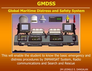
  • 1. GMDSS Global Maritime Distress and Safety System This will enable the student to know the basic emergency and distress procedures by INMARSAT System, Radio communications and Search and Rescue 2M LEONILO S. DANGALAN
  • 2. GMDSS The GMDSS offers the greatest advancement in maritime safety since the enactment of regulations following the Titanic disaster in 1912 . GMDSS is a global coverage and arrangement of communication systems for maritime distress and safety communication that search and rescue authorities, as well as shipping in the immediate vicinity of the ship or person in distress, as well be rapid alerted, so that they can assist in a coordinated search and rescue operation in minimum delay.
  • 3. GMDSS History The Global Maritime Distress and Safety System (GMDSS) represents a significant improvement in marine safety over the previous system of short range and high seas radio transmissions. Its many parts include satellite as well as advanced terrestrial communications systems. SOLAS 74/78 – Chapter IV contains the GMDSS provisions, which entered into on force 01 February 1992, with full implementation scheduled by 1 February 1999.
  • 4. GMDSS History Samuel Finley Breeze Morse was born in Charlestown, Mass. on 27th April 1791. He was not a scientist - he was a professional artist. Educated at Phillip s Academy at Andover, he graduated from Yale in 1810 and he lived in England from 1811 to 1815, exhibiting at the Royal Academy in 1813. He spent the next ten years as an itinerant artist with a particular interest in portraiture. He returned to America in 1832 having been appointed Professor of Painting and Sculpture at the University of the City of New York. It was on this homeward voyage that he overheard a shipboard discussion on electromagnets. This was the seed out of which the electric telegraph grew. Morse is remembered for his Code, still used, and less for the invention that enabled it to be used, probably since landline telegraphy eventually gave way to wireless telegraphy.
  • 5. GMDSS History Since the invention of the radio at the end of the 19th century, ships at sea have relied on MORSE CODE , invented by SAMUEL MORSE and first used in 1844, for distress and safety telecommunications. The need for ship and coast radio stations to have and use radiotelegraph equipment, and to listen to a common radio frequency for Morse encoded distress calls, was recognized after the sinking of the liner RMS TITANIC in the North Atlantic in 1912. Early Morse Signals
  • 6. GMDSS History Second Radio Officer, and in the logs of the SS Carpathia, Titanic first used "CQD" to call for help. When Captain Smith gave the order to radio for help, first radio officer Jack Phillips sent "CQD" six times followed by the Titanic call lette s, "MGY. Vibroplex key of 1910
  • 7. GMDSS History There is much mystery and misinformation surrounding the origin and use of maritime distress calls. Most of the general populace believes that "SOS" signifies "Save Our Ship." Casual students of radio history are aware that the use of "SOS" was preceded by "CQD." Why were these signals adopted? When were they used? The practical use of wireless telegraphy was made possible by Guglielmo Marconi in the closing years of the 19th century. Until then, ships at sea out of visual range were very much isolated from shore and other ships. The wireless telegraphers used Morse Code to send messages. Morse Code is a way of "tapping" out letters using a series of dots (short signals) and dashes (long signals). Spoken, short signals are referred to as "dih" and long signals are referred to as "dah". The letter "A" is represented by a dot followed by a dash: = A Guglielmo Marconi
  • 8. GMDSS History The Marconi Yearbook of Wireless Telegraphy and Telephony , 1918 states, "This signal [SOS] was adopted simply on account of its easy radiation and its unmistakable character. There is no special signification in the letter themselves, and it is entirely incorrect to put full stops between them [the letters]." All the popular interpretations of "SOS," "Save Our Ship," "Save Our Souls," or "Send Out Succour" are simply not valid. Stations hearing this distress call were to immediately cease handling traffic until the emergency was over and were likewise bound to answer the distress signal. Although the use of "SOS" was officially ratified in 1908, the use of "CQD" Lingered for several more years, especially in British service where it originated.
  • 9. GMDSS History In 1904, the Marconi company suggested the use of "CQD" for a distress signal. Although generally accepted to mean, "Come Quick Danger," that is not the case. It is a general call, "CQ," followed by "D," meaning distress. A strict interpretation would be "All stations, Distress." At the second Berlin Radiotelegraphic Conference 1906, the subject of a danger signal was again addressed. Considerable discussion ensued and finally SOS was adopted. The thinking was that three dots, three dashes and three dots could not be misinterpreted. It was to be sent together as one string.
  • 10. GMDSS History By 1904 there were many trans-Atlantic British ships equipped with wireless communications. The wireless operators came from the ranks of railroad and postal telegraphers. In England a general call on the landline wire was a "CQ." "CQ" preceded time signals and special notices. "CQ" was generally adopted by telegraph and cable stations all over the world. By using "CQ," each station receives a message from a single transmission and an economy of time and labor was realized. Naturally, "CQ," went with the operators to sea and was likewise used for a general call. This sign for "all stations" was adopted soon after wireless came into being by both ships and shore stations.
  • 11. GMDSS History The first recorded American use of "SOS" was in August of 1909. Wireless operator T. D. Haubner of the SS Arapahoe radioed for help when his ship lost its screw near Diamond Shoals, sometimes called the "Graveyard of the Atlantic." The call was heard by the United Wireless station "HA" at Hatteras. A few months later, the SS Arapahoe received an "SOS" distress call from the SS Iroquois. Radio Officer Haubner therefore has the distinction of being involved in the first two incidents of the use of "SOS" in America, the first as the sender and the second as the receiver. The U.S. did not officially adopt "SOS" until 1912, being slow to adopt international wireless standards SS Arapahoe SS Iroquois
  • 12. GMDSS History The United States congress enacted legislation soon after, requiring U.S. ships to use Morse code radiotelegraph equipment for distress calls. The INTERNATIONAL TELECOMMUNICATIONS UNION (ITU), now a United Nations agency, followed suit for ships of all nations. Morse encoded distress calling has saved thousands of lives since its inception almost a century ago, but its use requires skilled radio operators spending many hours listening to the radio distress frequency. Its range on the Medium Frequency (MF) distress band (500 kHz) is limited, and the amount of traffic Morse signals can carry is also limited.
  • 13. GMDSS History Not all ship-to-shore radio communications were short range. Some radio stations provided long-range radiotelephony services, such as radio telegrams and radio telex calls, on the HIGH FREQUENCY (HF) bands (3-30 mHz) enabling worldwide communications with ships. For example, Portishead radio, which was the world's busiest radiotelephony station, provided HF long-range services. In 1974, it had 154 radio operators who handled over 20 million words per year.Such large radiotelephony stations employed large numbers of people and were expensive to operate. By the end of the 1980s, satellite services had started to take an increasingly large share of the market for ship-to-shore communications
  • 14. GMDSS History It spelled the end of Morse code communications for all but a few users, such as Amateur Radio Operators. The GMDSS provides for automatic distress alerting and locating in cases where a radio operator doesn't have time to send an SOS or MAYDAY call, and, for the first time, requires ships to receive broadcasts of maritime safety information which could prevent a distress from happening in the first place. In 1988, IMO amended the Safety of Life at Sea (SOLAS) Convention, requiring ships subject to it fit GMDSS equipment. Such ships were required to carry NAVTEX and satellite EPIRBs by 1 August 1993, and had to fit all other GMDSS equipment by 1 February 1999. US ships were allowed to fit GMDSS in lieu of Morse telegraphy equipment by the Telecommunications Act of 1996
  • 15. GMDSS History For these reasons, the INTERNATIONAL MARITIME ORGANIZATION (IMO), a United Nations agency specializing in safety of shipping and preventing ships from polluting the seas, began looking at ways of improving maritime distress and safety communications. In 1979, a group of experts drafted the International Convention on Maritime Search and Rescue, which called for development of a global search and rescue plan. This group also passed a resolution calling for development by IMO of a Global Maritime Distress and Safety System (GMDSS) to provide the communication support needed to implement the search and rescue plan. This new system, which the world's maritime nations are implementing, is based upon a combination of Satellites and terrestrial radio services, and has changed international distress communications from being primarily ship-to-ship based to ship-to-shore (Rescue Coordination Center)based.
  • 16. GMDSS Licensing of Operators Natio al a iti e autho ities a issue a ious lasses of li e ses. The Ge e al Ope ato s Certificate is required on SOLAS vessels operating also outside GMDSS Sea Area A1, while a ‘est i ted Ope ato s Ce tifi ate is eeded o “OLA“ essels ope ated solel ithi GMD““ Sea Area A1, Long Range Certificate may be issued, and is required on non-SOLAS vessels operating outside GMDSS Sea Area A1, while a Short Range Certificate is issued for non-SOLAS vessels operating only inside GMDSS Sea Area A1. Finally there is a Restricted radiotelephone operator's certificate, which is similar to the Short Range Certificate but limited VHR DSC radio operation. Some countries do not consider this adequate for GMDSS qualification.
  • 17. GMDSS Licensing of Operators In the United States four different GMDSS certificates are issued. A GMDSS Radio Maintainer's License allows a person to maintain, install, and repair GMDSS equipment at sea. A GMDSS Radio Operator's License is necessary for a person to use required GMDSS equipment. The holder of both certificates can be issued one GMDSS Radio Operator/Maintainer License. Finally, the GMDSS Restricted License is available for VHF operations only within 20 nautical miles (37 km) of the coast. To obtain any of these licenses a person must be a U.S. citizen or otherwise eligible for work in the country, be able to communicate in English, and take written examinations approved by the Federal Communications Commission. Like the Amateur Radio examinations, these are given by private, FCC-approved groups. These are generally not the same agencies who administer the ham tests. Written test elements 1 and 7 are required for the Operator license, and elements 1 and 7R for the Restricted Operator. (Passing element 1 also automatically qualifies the applicant for the Marine Radiotelephone Operator Permit, the MROP.)
  • 18. GMDSS Licensing of Operators For the Maintainer license, written exam element 9 must be passed. However, to obtain this certificate an applicant must also hold a General radiotelephone License (GROL), which requires passing commercial written exam elements 1 and 3 (and thus supersedes the MROP). Upon the further passing of optional written exam element 8 the ship radar endorsement will be added to both the GROL and Maintainer licenses. This allows the holder to adjust, maintain, and repair shipboard Radar equipment. Until March 25, 2008 GMDSS operator and maintainer licenses expired after five years but could be renewed upon payment of a fee. On that date all new certificates were issued valid for the lifetimes of their holders. For those still valid but previously issued with expiration dates, the FCC states: Any GMDSS Radio Operator's License, Restricted GMDSS Radio Operator's License, GMDSS Radio Maintainer's License, GMDSS Radio Operator/Maintainer License, or Marine Radio Operator Permit that was active, i.e., had not expired, as of March 25, 2008, does not have to be renewed. Since an older certificate does show an expiration date, for crewmembers sailing internationally it may be worth paying the fee (as of 2010 it was $60) to avoid any confusion with local authorities. Finally, to actually serve as a GMDSS operator on most commercial vessels the United states Coast Guard requires additional classroom training and practical experience beyond just holding a license
  • 19. GMDSS Background The GMDSS was adopted by amendments in 1988 by the Conference of Contracting Governments to the International Convention for the Safety of Life at Sea (SOLAS), 1974. This was the culmination of more than a decade of work by the International Maritime Organization (IMO) in conjunction with the International Telecommunications Union (ITU), International Hydrographic Organization (IHO), World Meteorological Organization (WMO), International Maritime Satellite Organization (INMARSAT), and others communications.
  • 20. GMDSS The Global Maritime Distress and Safety System (GMDSS) is an internationally agreed-upon set of safety procedures, types of equipment, and communication protocols used to increase safety and make it easier to rescue distressed ships, boats and aircraft. GMDSS these limitations by introducing modern communication technology, including satellites and digital selective calling techniques to transmit and receive distress alerts automatically over long ranges reliably.
  • 21. GMDSS Concept All ships must perform 9 specific functions irrespective of where they are at sea: 1. Ship-to-shore distress alerting. 2. Shore-to-ship distress alerting. 3. Ship-to-ship distress alerting. 4. SAR coordination. 5. On-scene communications. 6. Transmission and receipt of emergency locating signals. 7. Transmission and receipt of MSI. 8. General radio communications. 9. Bridge-to-bridge communications.
  • 22. GMDSS 9 Important Functions SHIP to SHORE: All ships shall be able to send or transmit alert DISTRESS by ship to shore communication in at least two independent ways. “hip s Ide tifi atio “hip s Positio Time the position is valid Nature of Distress
  • 23. GMDSS 9 Important Functions SHIP to SHIP: All ships shall be able to send or transmit alert DISTRESS by ship to ship communication using Digital Selective Calling (DSC) for all stations also sends Distress Alerts in ht e VHF, MF and HF bands.
  • 24. GMDSS 9 Important Functions SHORE to SHIP: A Rescue Coordinating Center (RCC) or Coast Radio Station (CRS) acknowledges the DISTRESS alerts and sending it to all ships. If it is necessary, the RCC or CRS relays the DISTRESS alerts to all Ships in the vicinity.
  • 25. GMDSS 9 Important Functions SEARCH and RESCUE Communication Are those necessary for the RCC to coordinate and control the communication in search and rescue operation. With the following methods of communications. Telephony and Telex Terrestrial or Satellite
  • 26. GMDSS 9 Important Functions ON-SCENE Communication Are normally on short range VHF and MF bands the frequency designated for safety and Distress communications. This is vital for the operation of ships in distress and for the rescue of survivors.
  • 27. GMDSS 9 Important Functions LOCATING Is the finding of the Ship in distress of survivors. In GMDSS this means finding the Search And Rescue Transponder (SART). The SART signal can be identified as 12 dot Racon echoes on a the screen of a 3cm radar.
  • 28. GMDSS 9 Important Functions BRIDGE to BRIDGE Communication Means a safety communication between ships. Channel 13 is reserved for short range communication safety of navigation and maneuvering traffic on VHF radio telephone.
  • 29. GMDSS 9 Important Functions MARINE SAFETY INFORMATION (MSI) MSI Broadcast includes navigational warnings meteorological warnings and forecast and other urgent safety information, ships with in the range of radio coast stations receive information through NAVTEX on 518 kHz, beyond coastal waters ships receive MSI information through satellite Safety NET service using the INMARSAT Enhanced Group Call (EGC) or by HF radio telex. Sample of NAVTEX MSI message ZCZC HB38 071930 UTC JUN GERMAN GALE WARNING 218 RISK OF STRONG SOUTH-WEST TO WEST TO WESTERLY WIND FORCCE 6 AT TIME* IN WESTERN AND SOUTHERN BALTIC… NNNN GMDSS ship beyond NAVTEX coverage shall receive MSI via: HF Radio Telex – World-wide Navigational Warning System (WWNWS) INMARSAT – ECG Safety NET
  • 30. GMDSS 9 Important Functions General Communication According to GMDSS are ship to shore communication other than safety, urgency and distress messages that may have an impact on the ships safety. It is also encourage to in routine communications
  • 31. GMDSS Basics Radio waves are a type of electromagnetic radiation with wavelengths in the electromagnetic spectrum longer than infrared light. Radio waves have frequencies from 300 GHz to as low as 3 kHz, and corresponding wavelengths from 1 millimeter to 100 kilometers. Like all other electromagnetic waves, they travel at the speed of light. Naturally occurring radio waves are made by lightning, or by astronomical objects. Artificially generated radio waves are used for fixed and mobile radio communication, broadcasting, radar and other navigation systems, communications satellites, computer networks and innumerable other applications. Different frequencies of radio waves have different propagation characteristics in the Earth's atmosphere; long waves may cover a part of the Earth very consistently, shorter waves can reflect off the ionosphere and travel around the world, and much shorter wavelengths bend or reflect very little and travel on a line of sight.
  • 32. GMDSS Basics The frequencies falling between three kilohertz to three hundred gigahertz are called radio frequencies since they are commonly used in radio communications. Radio frequencies spectrum is divided into eight frequency bands namely Very low frequency, Low frequency, Medium frequency, High frequency, Very high frequency, Ultra high frequency, Super high frequency and Extreme high frequency. Each of these frequencies is ten times higher in frequency as the one immediately below it. The term hertz was designated for use in lieu of the term cycles per second when referring to the frequency of radio waves. Hertz refer to the number of occurrences that take place in one second.
  • 33. Basics Radio Waves Radio waves can be transmitted from ones point to another by sky wave, ground waves direct waves and reflective waves, an HF radio waves radiated into space by an HF antenna are refracted on the ionosphere and back to the earths surface.
  • 34. Basics Radio Waves Direct and refracted radio waves are typical example of VHF radio waves
  • 35. Basics Atmospheric Layers Up to 4 distinct layers are present in the ionosphere at anytime these layers are very important for the propagation. during daylight hours the radiation of the sun produces 4 layers of the ionosphere. These are D layer at about 75,000 meters E Layer at about 100,000 meters F1 Layer at about 225,000 meters F2 Layer at about 320,000 meters
  • 36. Basics Atmospheric LAyers At sunset the atmospheric layers change the D layer disappears the E Layer at about 100,000 meters F Layer has combined into one and at about 250,000 meters
  • 37. Basics Propagation VHF day time The range of your radio is related to the propagation day or night the VHF is a short range radio used for communication to ship to ship and ship[ to shore during daytime.
  • 38. Basics Propagation VHF Night time At nighttime use the same frequencies and VHF Channel.
  • 39. Basics Propagation MF Day time MF is a medium range radio for communication used to ship to ship and ship to shore for example this specific MF frequency during day to communicate with another ship.
  • 40. Basics Propagations MF night time During nighttime you’ll be communicating with the same ship and also with another ship if you are using the same MF frequency.
  • 41. Basics Propagations HF Day time 16 MHz If you transmit a radio call from by a HF 16 MHz from south Africa to Australia successfully, if your call is between day and night zones 12 MHz is a good alternative. DO NOT use 4 MHz signals fall short.
  • 42. Basics Propagations HF Night time 16 MHz At night time 16 MHz will not work, if your call is between day and night zones 12 MHz is a good alternative.
  • 43. Basics Propagations HF Night time 8 MHz Again you send a radio call from south Africa to Australia using 8 MHz and it was successful. If your call is between day and night zones 12 MHz is a good alternative.
  • 44. Basics Satellite Day time You are transmitting a radio call by satellite along range communications, talking about transcontinental traffic from one ocean to another by satellite.
  • 45. Basics Satellite Night time You transmitted your radio call successfully long range communication is till using the same frequency at night time.
  • 46. GMDSS Ship requirements By the terms of the SOLAS Convention, the GMDSS provisions apply to cargo ships of 300 gross tons and over and ships carrying more than 12 passengers on international voyages. Unlike previous shipboard carriage regulations that specified equipment according to size of vessel, the GMDSS carriage requirements stipulate equipment according to the area the vessel operates in.
  • 47. GMDSS Recreational vessels do not need to comply with GMDSS radio carriage requirements, but will increasingly use the Digital Selective Calling (DSC) VHF radios channel 70 . Offshore vessels may elect to (2187,5 kHz) equip themselves further. Vessels under 300 Gross Tonnage (GT) are not subject to GMDSS requirements.
  • 48. GMDSS IMO and ITU both require that the DSC-equipped MF/HF and VHF radios be externally connected to a satellite navigation receiver (GPS). That connection will ensure accurate location information is sent to a rescue coordination center if a distress alert is transmitted. The FCC requires that all new VHF and MF/HF maritime radiotelephones type accepted after June 1999 have at least a basic DSC capability. VHF digital selective calling also has other capabilities beyond those required for the GMDSS.
  • 49. GMDSS Communication Equipments The worldwide communications coverage of the GMDSS is achieved by a combination of satellite (INMARSAT) and terrestrial communication arrangement Terrestrial Communications Long Range Service - HF Medium Range Service - MF Short Range Service - VHF Setellite Communications INMARSAT System COSPAS-SARSAT System
  • 50. GMDSS The Coast Guard uses this system to track vessels in Prince William Sound, Alaska, Vessel Traffic Service. IMO and the USCG also plan to require ships carry a Universal Shipborne Automatic Indentification System, which will be DSC-compatible. GMDSS telecommunications equipment should not be reserved for emergency use only. The International Maritime Organization encourages mariners to use GMDSS equipment for routine as well as safety telecommunications.
  • 51. Is required to meet the requirements of the functional areas above the following is a list of the minimum communications equipment needed for all ships: GMDSS Main types of equipments VHF radio capable of transmitting and receiving DSC on channel 70 and radio telephony on channels 6, 13 and 16. Radio receiver capable of maintaining a continuous DSC watch on channel 70 VHF. Search and rescue transponders (SART), a minimum of two, operating in the 9 GHz band. Receiver capable of receiving NAVTEX broadcasts anywhere NAVTEX service is available. Receiver capable of receiving SafetyNET anywhere NAVTEX is not available. Satellite emergency position indicating radiobeacon (EPIRB), manually activated or float- free self activated. Two-way handheld VHF radios (two sets minimum on 300-500 gross tons cargo vessels and three sets minimum on cargo vessels of 500 gross tons and upward and on all passenger ships). Until 1 Feb. 1999, a 2182 kHz watch receiver was not in use.
  • 52. RADIO DISTRESS COMMUNICATION DIGITAL SELECT CALLING (DSC) RADIO TELEPHONE RADIOTELEX DSC Channel 70 Channel 16 VHF 2187.5 kHz 2182.0 kHz 2174.5 kHz MH 4207.5 kHz 4125.0 kHz 4177.5 kHz HF4 6312.0 kHz 6215.0 kHz 6268.0 kHz HF6 8414.5 kHz 8291.0 kHz 8376.5 kHz HF8 12577.0 kHz 12290.0 kHz 12520.0 kHz HF12 16804.5 kHz 16420.0 kHz 16695.0 kHz HF16
  • 53. GMDSS Main types of equipments The Inmarsat C provides ship/shore, shore/ship and ship/ship store-and-forward data and email messaging, the capability for sending preformatted distress messages to a rescue coordination center, and the Inmarsat C SafetyNET service. The Inmarsat C SafetyNET service is a satellite-based worldwide maritime safety information broadcast service of high seas weather warnings, NAVAREA navigational warnings, radionavigation warnings, ice reports and warnings generated by the USCG- conducted International Ice Patrol, and other similar information not provided by NAVTEX. SafetyNET works similarly to NAVTEX in areas outside NAVTEX coverage. Inmarsat C equipment is relatively small and lightweight, and costs much less than an Inmarsat B or F77. Inmarsat B and F77 ship earth stations which require relatively large gyro-stabilized uni directional antennas; the antenna size of the Inmarsat C is much smaller and is omni directional.
  • 54. GMDSS Main types of equipments Under a cooperative agreement with the National Oceanic and Atmospheric Administration (NOAA), combined meteorological observations and AMVER reports can now be sent to both the USCG AMVER Center, and NOAA, using an Inmarsat C ship earth station, at no charge. . SOLAS now requires that Inmarsat C equipment have an integral satellite navigation receiver, or be externally connected to a satellite navigation receiver. That connection will ensure accurate location information to be sent to a rescue coordination center if a distress alert is ever transmitted. Also the new LRIT long range tracking systems are upgraded via GMDSS Inmarsat C which are also compliant along with inbuilt SSAS, or Ship Security Alert System. SSAS provides a means to covertly transmit a security alert distress message to local authorities in the event of a mutiny, pirate attack, or other hostile action towards the vessel or its crew.
  • 55. Equipments HF DSC A GMDSS system may include High Frequency (HF) radiotelephone and Radiotelex (narrow-band direct printing) equipment, with calls initiated by digital selective calling (DSC). Worldwide broadcasts of maritime safety information can also made on HF narrow-band direct printing channels.
  • 56. Equipments VHF Radios Is is a short range radio communication to other ship or from Shore to ship.
  • 57. Is used for on-scene communications between life rafts, ships and rescue units it may also be used for onboard communications. Batteries intended for use in Distress situations should not be used for on-board communications. Equipments Portable VHF Radios
  • 58. GMDSS Radio equipment required for US coastal voyage Presently, until an A1 or A2 Sea Area is established, GMDSS- mandated ships operating off the U.S. coast must fit to Sea Areas A3 (or A4) regardless of where they operate. U.S. ships whose voyage allows them to always remain within VHF channel 16 coverage of U.S. Coast Guard stations may apply to the Federal Communications Commission for an individual waiver to fit to Sea Area A1 requirements. Similarly, those who remain within 2182 kHz coverage of U.S. Coast Guard stations may apply for a waiver to fit to Sea Area A2 requirements.
  • 59. The IMO also introduced Digital Selective Calling (DSC) on MF, HF and VHF Marine Radios as part of the GMDSS system. DSC is primarily intended to initiate ship-to-ship, ship-to-shore and shore- to-ship radiotelephone and MF/HF radio telex calls. DSC calls can also be made to individual stations, groups of stations, or "all stations" in one's radio range. Each DSC-equipped ship, shore station and group is assigned a unique 9- digit Maritime Mobile Service Identity. DSC distress alerts, which consist of a preformatted distress message, are used to initiate emergency communications with ships and rescue coordination centers. DSC was intended to eliminate the need for persons on a ship's bridge or on shore to continuously guard radio receivers on voice radio channels, including VHF channel 16 (156.8 MHz) and 2182 kHz now used for distress, safety and calling. A listening watch aboard GMDSS- equipped ships on 2182 kHz ended on February 1, 1999. In May 2002, IMO decided to postpone cessation of a VHF listening watch aboard ships. That watch keeping requirement had been scheduled to end on 1 February 2005. Equipments DSC Radios
  • 60. VHF DSC Distress Alert Contents of Transmission: “hips Ide tit – MMSI Nature of Distress ship s last k o Positio the time position was valid Watching channel VHF Ch 70 Subsequent communication follows on VHF Ch 16 DSC DISTRESS Alerts go through very quickly as it is subsequently connected the differently nautical equipment on the bridge such as GPS. Equipments DSC Radios
  • 61. MF - HF DSC Distress Alert Contents of Transmission: “hips Ide tit – MMSI Distress Frequency Nature if Distress ship s last k o Positio the time position was valid Subsequent communication follows on Telephony or Telex GMDSS equipped ship with MF – HF DSC must maintain watch on MF 2187.5 KHz and the HF 8414.5 KHz and least one of the other DSC Frequencies. NOTE: if e uip e t is update f o GP“, ship s positio is auto ati all updated. Othe ise the ship s positio ust e updated a uall e e hou s. Equipments DSC Radios
  • 62. DSC Distress Frequency MF band; 2187.5 kHz 4207.5 kHz, 6312 kHz, 8414.5 kHz, (Emergency) HF band; 12577 kHz 16804.5 kHz VHF band. 156.525 MHz (channel 70) 8414,5 kHz 4207,5 kHz 6312 kHz 12577 kHz 1604,5 kHz Other frequencies depending on the time of the day
  • 65. Provides tow way telephony and telex communication the telephone channel can also provides fax and data communication. A push button gives Distress priority for a telephone or telex call. Equipments INMARSAT B System
  • 66. Is a store and forward messaging system a message from a ship can be send from a telex fax o o pute asho e. You a se d a Dist ess ale t ith the ship s ide tit , positio a d ti e pressing the Distress button, and the INMARSAT C is one way of receive maritime safety information. NOTE: if equipment is update f o GP“, ship s positio is automatically updated. Othe ise the ship s positio must be updated manually every 4 hours. The antenna is small and shall be installed to insure that you stay in line of sight of the satellite. The transceiver interface with the and the satellite system, this transceiver consist of a transmitter and a receiver to ensure safe communication by a satellite to the Coast Earth Station (CES). Equipments INMARSAT C System
  • 67. Mandatory if the ship is required to carry and HF radio installation. an alternative to radio telephony for distress and general radio communication used for receiving MSI transmitted on HF frequencies Equipments Radio Telex
  • 68. EPIRB – one of the most important life saving equipment. Operating EPIRB means that somebody is in distress and an immediate assistance is needed. If the vessel sinks, the EPIRB will be automatically released from the bracket when It transmit Ships Position and Identity; Position information and Additional information which could facilitate rescue unless integrated position fixing device, a 9 GHz radar transponder is activated for location purposes. Battery operation must be sufficient to operate for 4 hours or for 48 hours, integral features are included for automatic upgrading. Must operate in an environmental condition of ambient temperature of 20ºC – 55ºC , icing condition, relative wind speed of 100 knots and stowage temperature of 30ºC – 65ºC. Early EPIRBS transmit on an aircraft frequencies of: 121.5 mHz - for civil emergencies 243 mHz - for military frequencies 406 mHz - to give stable fixing for satellites 1.6 GHz - with GPS receiver for INMARSAT-EPIRB subjected to water pressure at 2-4 meters depth and then float up to the surface. Due to the function of the seawater contacts it will automatically be activated and start to transmit vessels identity and positioning signals to the the COSPAS/SARSAT satellites. It should be examined for physical damages every week. The expiration date or service date of the HRU should be noted. Emergency Position Indicating Radio Beacon (EPIRB)
  • 69. EPIRBS Classifications Type Frequency Description Class A 121.5/243 MHz Float-free, automatic activating, detectable by aircraft and satellite. Coverage limited (see Figure 2908). Class B 121.5/243 MHz Manually activated version of Class A. Class C VHF Ch. 15/16 Manually activated, operates on maritime channels only. Not detectable by satellite. Class S 121.5/243 MHz Similar to Class B, except that it floats, or is an integral part of a survival craft. Category I 121.5/406 MHz Float-free, automatically activated. Detectable by satellite anywhere in the world. Category II 121.5/406 MHz Similar to Category I, except manually activated.
  • 70. L-Band Satellite EPIRB This provides rapid distress alerting through the INMARSAT System Coverage up to +/- 70° Latitudes 20 simultaneous alerts within 10 min. time frame IT OPERATES it transmit 1.6 Ghz Frequency activates either automatic or manually after activation the EPIRB transmit: ship’s position identity position information additional information which could facilitate rescue unless integrated position-fixing device, a 9 GHz RADAR transponder is attached for locating purposes Battery operated must operate for 4 hours or 48 hours if integral features are included for automatic updating Must operate in environment conditions of: Ambient temp of -20°C up to 55°C Icing Relative wind speed of up to 100 knots Storage temp between 30°C and 65°C The basic Concept of L-Band satellite EPIRB MES/SES to Satellite Uplink 1626.5.0 mHz to 1646.5 mHz (1.6 Ghz) Satellite to CES/LES downlink 3600.0 to 3623.0 mHz (4Ghz)
  • 71. EPIRBS Descriptions and Capabilities 121.5/243 MHz EPIRB’s (Class A, B, S): These are the most common and least expensive type of EPIRB, designed to be detected by overflying commercial or military aircraft. Satellites were designed to detect these EPI‘B s but are limited for the following reasons: 1. Satellite detection range is limited for these EPI‘B s (satellites must be within line of sight of both the EPIRB and a ground terminal for detection to occur). 2. EPIRB design and frequency congestion cause them to be subject to a high false alert/false alarm rate (over 99%); consequently, confirmation is required before SAR forces can be deployed; 3. EPI‘B s manufactured before October 1988 may have design or construction problems (e.g. some models will leak and cease operating when immersed in water) or may not be detectable by satellite.
  • 72. EPIRBS Descriptions and Capabilities Class C EPIRB’s: These are manually activated devices intended for pleasure craft which do not venture far offshore, and for vessels on the Great Lakes. They transmit a short burst on VHF-FM 156.8 MHz (Ch. 16) and a longer homing signal on 156.75 MHz (Ch. 15). Their usefulness depends upon a coast station or another vessel guarding channel 16 and recognizing the brief, recurring tone as an EPIRB. Class C EPI‘B s are not recognized outside of the United States. Class C EPI‘B s cannot be manufactured or sold in the United States after February 1995. Class C EPI‘B s installed on board essel s prior to February 1995 may be utilized until 1 February 1999 and not thereafter.
  • 73. EPIRBS Descriptions and Capabilities 406 MHz EPIRB’s Catego y I, II : The 406 MHz EPIRB was designed to operate with satellites. Its signal allows a satellite local user terminal to locate the EPIRB (much more accurately than 121.5/243 MHz devices) and identify the essel the sig al is e oded ith the essel s ide tit anywhere in the world. There is no range limitation. These devices also include a 121.5 MHz homing signal, allowing aircraft and rescue vessels to quickly find the vessel in distress. These are the only type of EPIRB which must be tested by Coast Guard-approved independent laboratories before they can be sold for use within the United States. An automatically activated, float-free version of this EPIRB has been required on SOLAS vessels (cargo ships over 300 tons and passenger ships on international voyages) since 1 August 1993. The Coast Guard requires U.S. commercial fishing vessels to carry this device (unless they carry a Class A EPIRB), and will require the same for other U.S. commercial uninspected vessels which travel more than 3 miles offshore.
  • 74. EPIRBS Descriptions and Capabilities Mariners should be aware of the differences between capabilities of 121.5/243 MHz and . / MHz EPI‘B s, as the ha e implications for alerting and locating of distress sites, as well as response by SAR forces. The advantages of 121.5/406 MHz devices are substantial, and are further enhanced by EPIRB- transmitted registration data on the carrying essel. O e s of . / MHz EPI‘B s furnish registration information about their vessel, survival gear, and emergency points of contact ashore, all of which greatly enhance the response. The database for U.S. vessels is maintained by the National Oceanographic and Atmospheric Administration, and is accessed worldwide by SAR authorities to facilitate SAR response.
  • 75. Testing EPIRBS EPIRB owners should periodically check for water tightness, battery expiration date, and signal presence. FCC rules allow Class A, B, and S EPI‘B s to be turned on briefly (for three audio sweeps, or 1 second only) during the first 5 minutes of any hour. Signal presence can be detected by an FM radio tuned to 99.5 MHz, or an AM radio tuned to any vacant frequency and located close to an EPIRB. FCC rules allow Class C EPI‘B s to be tested within the first 5 minutes of any hour, for not more than 10 seconds. Class C EPI‘B s can be detected by a marine radio tuned to channel 15 or 16. All 121.5/406 MHz EPI‘B s have a self- test function that should be used in accordance with a ufa tu e s instructions at least monthly.
  • 76. Alarm warning and alerting system If an EPIRB is activated, COSPAS/SARSAT picks up the signal, locates the source and passes the information to a land station. From there, the information is relayed, either via coast radio or satellite, to Rescue Coordination Centers, rescue vessels and nearby ships. This constitutes a one-way only communications system, from the EPIRB via the satellite to the rescuers. It employs low altitude, near polar orbiting satellites and by exploiting the Doppler principle, locates the transmitting EPIRB within about two miles. Due to the low polar orbit, there may by a delay in receiving the distress message unless the footprint of the satellite is simultaneously in view with a monitoring station. The 406 MHz EPI‘B s incorporate an identification code. The digital data coded into each 406 MHz EPI‘B s memory provides distress information to SAR authorities for more rapid and efficient rescue. The data includes a maritime identification digit (MID, a 3 digit number identifying the administrative country) and either a ship station identifier (SSI, a 6 digit number assigned to specific ships), a ship radio call sign or a serial number to identify the ship in distress. With the INMARSAT E satellite EPI‘B s, coverage does not extend to very high latitudes, but within the coverage area the satellite connection is instantaneous. However, to establish the EPI‘B s position, an interface with a GPS receiver or other sensor is needed.
  • 77. EPIRB Coverage Mode EPIRB 121.5 MHz 406.0 MHz Coverage Mode Real Time Mode Real Time Mode and Global Coverage Mode Position Locating Accuracy +/- 17.2 km 90% 5.0 km Transmit a 5Watts RF burst of 0.5sec. Every 50sec Capacity 10 EPIRBS Simultaneously 90 EPIRBS Simultaneously Certain Military Beacons transmit on 243 MHz
  • 78. EPIRBS Position Reporting Systems Feature 121.5/406 MHz EPIRB 121.5/243 MHz EPIRB Frequencies 406.025 MHz (locating) 121.500 MHz (civilian) 121.500 MHz (homing) 243.000 MHz (military) Primary Function Satellite alerting, locating, identification Transmission of distress signal to of distressed vessels. Passing aircraft and ships. Distress Confirmation Positive identification of coded beacon; Virtually impossible; no coded each beacon signal is a coded, unique information, beacons often signal with registration data (vessel incompatible with satellites; name, description, and telephone impossible to know if signals are from number ashore, assisting in confirmation). EPIRB, ELT, or non-beacon source. Signal Pulse digital, providing accurate beacon Continuous signal allows satellite location and vital information on locating at reduced accuracy; close distressed vessel. range homing. Signal Quality Excellent; exclusive use of 406 MHz for Relatively poor; high number of false distress beacons; no problems with false alarms caused by other transmitters in alerts from non-beacon sources. the 121.5 MHz band. Satellite Coverage Global coverage, worldwide detection; Both beacon and LUT must be within satellite retains beacon data until next coverage of satellite; detection limited earth station comes into view. to line of sight. Operational Time 48 hrs. at -20°C. 48 hrs. at -20°C Output Power 5 watts at 406 MHz, . 0.1 watts average. 025 watts at 121.5 MHz. Strobe Light High intensity strobe helps in visually `None. locating search target. Location Accuracy 1 to 3 miles (10.8 sq. miles); accurate 10 to 20 miles (486 sq. miles); SAR (Search (Search Area) and position on first satellite overflight forces must wait for second system Time Required enables rapid SAR response, often within alert to determine final position 30 min. before responding (1 to 3 hr. delay). Summary comparison of 121.5/406 MHz and 121.5/243 MHz EPIRB’s.
  • 79. Search And Rescue Transponder (SART) The GMDSS installation on ships include one (two on vessels over 500 GT) Search and Rescue Locating device(s) called Search and Rescue Radar Transponders (SART) which are used to locate survival craft or distressed vessels by creating a series of twelve dots on a rescuing ship's 3 cm RADAR display. The detection range between these devices and ships, dependent upon the height of the ship's radar mast and the height of the Search and Rescue Locating device, is normally about 15 km (8 nautical miles). Once detected by radar, the Search and Rescue Locating device will produce a visual and aural indication to the persons in distress.
  • 80. It operates in VHF frequencies between 9.2 - 9.5 GHz . As per GMDSS requirement it is used for locating ships in distress of their survival craft, and should have at least 96 hours sufficient power It should be mounted as high as possible. IMO require at least 5 n.mi. range. If it is mounted 1 meter above sea level and search antenna is 15m above sea level. SART lying on floor – 1.8 n.mi. SART standing upright - 2.5 n.mi. SART floating on the water - 2.0 n.mi. Search And Rescue Transponder (SART)
  • 81. SART within the vicinity 5 – 6 n. mi
  • 82. SART within the vicinity less than 5n.mi
  • 83. SART within the vicinity less than 1 n.mi
  • 84. NAVTEX NAVTEX is a maritime radio warning system consisting of a series of coast stations transmitting radio teletype (standard narrow-band direct printing, also sometimes called Sitor) safety messages on the internationally standard medium frequency of 518 kHz. Interference from or receipt of stations farther away occasionally occurs at night. The NAVTEX receiver is a small unit with an internal printer, which takes a minimum of room on the bridge. Its antenna is also of modest size, needing only a receive capability.
  • 85. It is an international, automated system for instantly distributing maritime safety information (MSI) which includes navigational warnings, weather forecasts and weather warnings, search and rescue notices and similar information to ships. The frequency of transmission of these messages is 518 kHz in English, while 490 kHz is sometime used to broadcast in a local language. The messages are coded with a header code identified by the using single letters of the alphabet to represent broadcasting stations, type of messages, and followed by two figures indicating the serial number of the message. For example: FA56 where F is the ID of the transmitting station, A indicates the message category Navigational warning, and 56 is the consecutive message number. NAVTEX
  • 86. GMDSS Power Supply If the main source of electrical power suddenly fail the accumulator provides power for at least one hour for your radio systems, and emergency source will take over when it is ready . All of this should be done automatically the emergency power should last for at least 18 hours.
  • 87. GMDSS Distress Transmitting Procedures by Radiotelephony This is a typical Distress alert by Radio Telephony
  • 88. GMDSS Distress Transmitting Procedures by Radiotelephony To be used only if IMMEDIATE ASSISTANCE is required USE PLAIN LANGUAGE WHENEVER POSSISBLE. If language difficulties are like to arise sending the word INTERCO to indicate that the message will be in the International Code of Signals
  • 89. GMDSS Reception of Safety Messages MAYDAY (Distress) Indicates that a Ship, Aircraft or other vehicle is threatened by grave and imminent danger and request immediate danger. Note: If you hear any of these words, pay particular attention to the message and call the Master or the Officer on watch
  • 90. GMDSS Reception of Safety Messages PANPAN (Urgency) Indicates that the calling station has a very urgent message to transmit concerning safety of a ship, aircraft or other vehicle, or the safety of a person. Note: If you hear any of these words, pay particular attention to the message and call the Master or the Officer on watch
  • 91. GMDSS Reception of Safety Messages SECURITE (Urgency) Indicates that the station is a about to transmit a message concerning safety of navigation or giving important meteorological warnings. Note: If you hear any of these words, pay particular attention to the message and call the Master or the Officer on watch
  • 92. GMDSS Reception of Safety Messages NATURE OF DISTRESS IN CODE FROM THE INTERNATIONAL CODE OF SIGNALS I require immediate assistance Charlie Bravo CB Aircraft is ditched in position indicated and requires immediate assistance Bravo Foxtrot BF I must abandon my vessel Alfa Echo AE I require immediate assistance, I am on fire Charlie Bravo Six CB6 I am sinking Delta X-Ray DX I have collided with surface craft Hotel Whiskey HW TEXT OF SIGNAL WORDS TO BE TRANSMITTED CODE LETTERS
  • 93. GMDSS Reception of Safety Messages ANSWER TO SHIP IN DISTRESS Repeat the Distress Signal Echo Lima EL Your Distress Signal are understood Echo Delta ED I am proceeding to your assistance Charlie Papa CP TEXT OF SIGNAL WORDS TO BE TRANSMITTED CODE LETTERS
  • 94. GMDSS Reception of Safety Messages NATURE OF DISTRESS IN CODE FROM SIGNALS FOR USE WHERE APPROPRIATE I ALL FORMS OF TRANSMISSION “Received” or “I have received your last Signal” Interrogative, or “The significance of the previous group should be read as a question’. “Word or group after…” (used after the “Repeat Signal” (RPT)) means “Repeat word or group after…” Repeat Signal “”I Repeat” or “repeat what you have sent” or “Repeat what you have received” “Word or group Before…” (used after the “Repeat Signal” (RPT)) means “Repeat word or group before…” “From…”(used to precede the name or Identity Signal of the Calling Station) “What is the Name and or Identity Signal of your vessel or Station Affirmative-YES or “the significance of the previous group should be read in the affirmative”. “I wish to communicate with you” or “Invitation to communicate” Negative-NO or the “the significance of the previous group should be read in the Negative”. When used in voice transmission the pronunciation should be “NO” Acknowledging a correct repetition or “It is correct” Ending signal or End of Transmission or Signal “All before…” (used after the “Repeat Signal” (RPT)) means “Repeat all Before…’ “All after…” (used after the “Repeat Signal” (RPT)) means “Repeat all After…’ Waiting Signal or Period “All between…and… (used after the “Repeat Signal” (RPT)) means “Repeat all in between…and…” R RQ WA RPT WB DE CS C K NO OK AR AB AA AS BN
  • 95. GMDSS Reception of Safety Messages SIGNALS TRANSMISSION FLASHING-LIGHT TRANSMISSION Full Stop or Decimal Point Erase Signal Call for Unknown station or General Call Answering Signal Word or Group Received AA AA AA etc EEEEEEE etc AAA TTTT T Note: The procedures “C”, “N” or “NO” and “RQ” cannot be used in conjunction with single letter signal Signal on COMMUNICATIONS. When these signals are used by voice transmission the letter should be pronounced in accordance with the letter spelling, with the exception of “NO” which in voice transmission should be pronounced as “NO”
  • 96. Cancellation of Distress Call When you have triggered a False or had send out an accidental Distress alert you have to know how to report before it triggers a rescue operation Keep watch at the GMDSS Station and wait for acknowledgment communicate with RCC that has acknowledge the alert If no acknowledgement received contact any RCC or Coast Station.
  • 97. In the event of a False Alert Keep watch at the GMDSS Station and wait for acknowledgment Communicate with RCC that has acknowledge the alert If no acknowledgement received contact any RCC or Coast Station. Make sure that the radio operators are aware of the serious consequences of a false alarm. Be careful of the equipment you are not familiar with. Routine testing should be done under the supervision of a qualified or designated operator. EPIRBs and SART signals should be tested not more than 10 seconds and should only tested by qualified personnel. To avoid sending out False Alerts Note: the best way to avoid False Alerts is to make sure that all personnel on the bridge are regularly trained o how to send distress alerts on the ship’s radio equipment.
  • 98. GMDSS INMARSAT Satellite System Satellite systems operated by the INMARSAT, overseen by IMSO, International Mobile satellite Organization are also important elements of the GMDSS. The types of Inmarsat ship earth station terminals recognized by the GMDSS are: Inmarsat B, C and F77. Inmarsat B and F77, an updated version of the now redundant Inmarsat A, provide ship/shore, ship/ship and shore/ship telephone, telex and high-speed data services, including a distress priority telephone and telex service to and from rescue coordination centers. Fleet 77 fully supports the Global Maritime Distress and Safety System (GMDSS) and includes advanced features such as emergency call prioritisation.
  • 99. The INMARSAT system The International Maritime Satellite Organization (INMARSAT), a key player within GMDSS, is an international consortium comprising over 75 international partners who provide maritime safety communications for ships at sea. In accordance with its convention, INMARSAT provides the space segment necessary for improving distress communications, efficiency and management of ships, as well as maritime correspondence services. The basic components of the INMARSAT system include the INMARSAT space segment, Land Earth Stations (LES), also referred to as Coast Earth Stations (CES), and mobile Ship Earth Stations (SES). The INMARSAT space segment consists of 11 geostationary satellites. Four operational INMARSAT satellites provide primary coverage, four additional satellites (including satellites leased from the European Space Agency (ESA) and the International Telecommunications Satellite Organization (INTELSAT) serve as spares and three remaining satellites (leased from COMSAT Corporation, the U.S. signatory to INMARSAT) serve as back-ups.
  • 100. The INMARSAT system The LE“ s p o ide the li k et ee the “pa e “eg e t a d the la d-based National/International fixed communications networks. These communications networks are funded and operated by the authorized communications authorities of a participating nation. This network links registered information providers to the LES. The data then travels from the LES to the INMARSAT Network Coordination Station (NCS) a d the do to the “E“ s o ships at sea. The “E“ s p o ide two-way communications between ship and shore. INMARSAT A, the original INMARSAT system, operates at a transfer rate of up to 9600 bits per second and is telephone, telex and facsimile (fax) capable. It is being replaced by a similarly sized INMARSAT B system that uses digital technology to give better quality fax and higher data transmission rates. INMARSAT C provides a store and forward data messaging capability (but no voice) at 600 bits per second and was designed specifically to meet the GMDSS requirements for receiving MSI data on board ship. These units are small, lightweight and use an omni-directional antenna.
  • 101. GMDSS GMDSS sea areas serve two purposes: to describe areas where GMDSS services are available, and to define what radio equipment GMDSS ships must carry (carriage requirements). Prior to the GMDSS, the number and type of radio safety equipment ships had to carry depended upon its tonnage. With GMDSS, the number and type of radio safety equipment ships have to carry depends upon the GMDSS areas in which they travel. In addition to equipment listed below, all GMDSS-regulated ships must carry a satellite EPIRB, a NAVTEX receiver (if they travel in any areas served by NAVTEX), an Inmarsat-C SafetyNET receiver (if they travel in any areas not served by NAVTEX), a DSC-equipped VHF radiotelephone, two (if between 300 and less than 500 GRT) or three VHF handhelds (if 500 GRT or more), and two 9 GHz search and rescue radar transponders (SART).
  • 102. Sea Area requirements under GMDSS Sea Area A1 1. General VHF radio telephone capability. 2. Free-floating EPIRB transmitting DSC on channel 70 VHF, or satellite EPIRB. 3. Capability of initiating a distress alert from a navigational position using DSC on either VHF, HF or MF; manually activated EPIRB; or Ship Earth Station (SES). Sea Areas A1 and A2 1. Radio telephone MF 2182 kHz and DSC on 2187.5 kHz. 2. Equipment capable of maintaining a continuous DSC watch on 2187.5 kHz. 3. General working radio communications in the MF band 1605-4000 kHz, or INMARSAT SES. 4. Capability of initiating a distress alert by HF (using DSC), manual activation of an EPIRB, or INMARSAT SES. Sea Areas A1, A2 and A3 1. Radio telephone MF 2182 kHz and DSC 2187.5 kHz. 2. Equipment capable of maintaining a continuous DSC watch on 2187.5 kHz. 3. INMARSAT A, B or C (class 2) SES Enhanced Group Call (EGC), or HF as required for sea area A4. 4. Capability of initiating a distress alert by two of the following: a. INMARSAT A, B or C (class 2) SES. b. Manually activated satellite EPIRB. c. HF/DSC radio communication. Sea Area A4 1. HF/MF receiving and transmitting equipment for band 1605-27500 kHz using DSC, radiotelephone and direct printing. 2. Equipment capable of selecting any safety and distress DSC frequency for band 4000-27500 kHz, maintaining DSC watch on 2187.5, 8414.5 kHz and at least one additional safety and distress DSC frequency in the band. 3. Ability to initiate a distress alert from a navigational position via the Polar Orbiting System on 406 MHz (manual activation of 406 MHz satellite EPIRB).
  • 103. Sea Area requirements under GMDSS INMARSAT GMDSS was develop to ensure safety com all around the world. Every waters is defined to as being divided into four sea areas. Your ships should be equipped with the appropriate GMDSS equipment for the different sea areas The INMARSAT system covers the entire worlds between Lat: 70° N and 70° S each satellites has its own country code telephonies and for telex.
  • 104. SEA AREA 1 Atlantic Ocean Region West Long: 53º W An area within range of at least one VHF coast Station in which continuous DSC alerting is available Distance: Depends on the antenna height of VHF coast stations, about 20-50 nm Offshore. Radio Frequencies: VHF Radio telephone 156.525 mHz (DSC Ch 70) 156.8 mHz (Ch 16) Radio Communications System EPIRBS: either 406 Mhz COSPAS-SARSAT or L-Band (1.6 Ghz) VHF EPIRB Survival Crafts: 9 GHz SART VHF Portable Radio Carriage Requirements VHF with DSC SART (2 units) NAVTEXT (only if Area has NAVTEX Service) ECG (Required if Area has no NAXTEX Coverage) EPIRB Portable VHF (2 -3 units) 2182 kHz watch Receiver 9until 01 FEB 1999) 2182 kHz 2 tone alarm signal (until 01 FEB 1999)
  • 105. An area Excluding Sea Area 1, with in the radio Telephone coverage of at least one MF Coast Station in which continuous DSC alerting is available. Radio Frequencies: MF and VHF Radio 2182 kHz radio telephone 2187.5 kHz DSC 2174.5 kHz NBDP 518 kHz NAVTEX Radio Communications System EPIRBS: 406 Mhz COSPAS-SARSAT or L-Band (1.6 Ghz) Survival Crafts: 9 GHz SART VHF Portable Radio Distance: about from A1 limit to 50 - 400 n. miles offshore Carriage Requirements VHF with DSC SART (2 units) NAVTEXT (only if Area has NAVTEX Service) ECG (Required if Area has no NAXTEX Coverage) EPIRB Portable VHF (2 -3 units) 2182 kHz watch Receiver 9until 01 FEB 1999) 2182 kHz 2 tone alarm signal (until 01 FEB 1999) MF Radio Telephone with DSC SEA AREA 2 Atlantic Ocean Region East Long: 15,5º W
  • 106. An Area excluding Sea Area A1 and A2, within the coverage of INMARSAT GEOSTATIONARY satellite in which continuous alerting is available Distance: 70° North - 70° South Radio Frequencies: HF or Satellite MF and VHF As A1 and A2 plus 1.5 – 1-6 GHz alerting or A1 and A2 plus all HF frequencies Radio Communications System EPIRBS: 406 Mhz COSPAS-SARSAT or L-Band (1.6 Ghz) Survival Crafts: 9 GHz SART VHF Portable Radio Carriage Requirements: VHF with DSC SART (2 units) NAVTEXT (only if Area has NAVTEX Service) ECG (Required if Area has no NAXTEX Coverage) EPIRB Portable VHF (2 -3 units) 2182 kHz watch Receiver 9until 01 FEB 1999) 2182 kHz 2 tone alarm signal (until 01 FEB 1999) MF Radio Telephone with DSC INMARSAT A,B, or C HF Radio Telephone DSC and TELEX SEA AREA 3 Indian Ocean Region Long: 64º E
  • 107. An area outside sea Areas A1, A2 and A3 includes the Polar Regions, where Geostationary Satellite coverage is not available Distance: North of 70°N-South of 70°S Radio Frequencies: HF or Satellite MF VHF Radio Communications System EPIRBS: 406 Mhz COSPAS-SARSAT Survival Crafts: 9 GHz SART VHF Portable Radio Carriage Requirements: VHF with DSC SART (2 units) NAVTEXT (only if Area has NAVTEX Service) ECG (Required if Area has no NAXTEX Coverage) EPIRB (406 MHz COSPAS – SARSAT) Portable VHF (2 -3 units) 2182 kHz watch Receiver 9until 01 FEB 1999) 2182 kHz 2 tone alarm signal (until 01 FEB 1999) MF Radio Telephone with DSC INMARSAT A,B, or C HF Radio Telephone DSC and TELEX SEA AREA 4 Pacific Ocean Region West Long: 178º E
  • 108. GMDSS equipment requirement - A1 – area within range of a VHF Coast Station with DSC SEA AREAS – A1 VHF with DSC DSC watch receiver Ch 70 NAVTEX INMARSAT ECG or HF Telex EPIRB Portable VHF 2 units (300-500 GWT) 3 units (above 500 DWT) SART 1 unit (300 – 500 DWT) 2 units (above 500 DWT) Additional for Passenger Ships Distress Panel Automatic updating of position to all relevant radio communication equipment Two-way on scene communication on 121.5 MHz and 123.1 MHz on the navigating Bridge
  • 109. GMDSS equipment requirement - A2 – all areas A1, A2, A3 and that is the Polar Area SEA AREAS – A2 VHF with DSC DSC watch receiver Ch 70 MF Telephony – MF DSC DSC watch receiver 2187,5 NAVTEX INMARSAT ECG or HF Telex EPIRB Portable VHF 2 units (300-500 GWT) 3 units (above 500 DWT) SART 1 unit (300 – 500 DWT) 2 units (above 500 DWT) Additional for Passenger Ships Distress Panel Automatic updating of position to all relevant radio communication equipment Two-way on scene communication on 121.5 MHz and 123.1 MHz on the navigating Bridge
  • 110. GMDSS equipment requirement - A3 – area within coverage of the INMARSAT satellite system but outside the areas A1 and A2. SEA AREAS – A3 VHF with DSC DSC watch receiver Ch 70 Duplicated VHF – DSC NAVTEX INMARSAT ECG or HF Telex EPIRB Portable VHF 2 units (300-500 GWT) 3 units (above 500 DWT) SART 1 unit (300 – 500 DWT) 2 units (above 500 DWT) Additional either: INMARSAT MF with MF DSC DSC watch receiver 2187,5 duplicated INMARSAT HF solution MF HF Telephone with DSC and NBDP (radio Telex) MF HF DSC duplicated INMARSAT or NBDP terminal
  • 111. GMDSS equipment requirement - A4 – area within coverage of the INMARSAT satellite system but outside the areas A1 and A2. SEA AREAS – A4 VHF with DSC DSC watch receiver Ch 70 MF HF Telephone with DSC and NBDP (radio Telex) Duplicated VHF – DSC Duplicated MF HF Telephone with DSC and NBDP (radio Telex) NAVTEX EPIRB Portable VHF 2 units (300-500 GWT) 3 units (above 500 DWT) SART 1 unit (300 – 500 DWT) 2 units (above 500 DWT) Additional for Passenger Ships Distress Panel Automatic updating of position to all relevant radio communication equipment Two-way on scene communication on 121.5 MHz and 123.1 MHz on the navigating Bridge
  • 112. GMDSS Sea Area Sea Areas A1, A2 and A3 1. Radio telephone MF 2182 kHz and DSC 2187.5 kHz. 2. Equipment capable of maintaining a continuous DSC watch on 2187.5 kHz. 3. INMARSAT A, B or C (class 2) SES Enhanced Group Call (EGC), or HF as required for sea area A4. 4. Capability of initiating a distress alert by two of the following: a. INMARSAT A, B or C (class 2) SES. b. Manually activated satellite EPIRB. c. HF/DSC radio communication.
  • 113. GMDSS Sea Area Sea Area A4 1. HF/MF receiving and transmitting equipment for band 1605-27500 kHz using DSC, radiotelephone and direct printing. 2. Equipment capable of selecting any safety and distress DSC frequency for band 4000-27500 kHz, maintaining DSC watch on 2187.5, 8414.5 kHz and at least one additional safety and distress DSC frequency in the band. 3. Ability to initiate a distress alert from a navigational position via the Polar Orbiting System on 406 MHz (manual activation of 406 MHz satellite (EPIRB).
  • 114. Area Codes for Contacting Ships and Coast Stations TELEX TEL/FAX DATA 581 871 AOR - E 582 872 1112 1111 POR 583 873 1113 IOR 584 874 1114 AOR - W CODE 00 32 SERVICE Automatic Dialing Medical Advice SERVICE Use this code to make automatic telex calls using International telex country codes Use this code to obtain medical advice. Some LESs have direct connection to Local Hospitals. 38 Medical Assistance Use this code if the condition of an ill or injured person requires urgent evacuation ashore or doctors medical service onboard. The call is routed to appropriate agency/authority ashore 39 Maritime Assistance Use this code to obtain maritime assistance if the vessel require immediate help such as Tugs, Oil Pollution team, etc. 42 Navigational hazards and Warnings This code provides connection to navigational Office for transmission of information from the vessel or any hazards which could endanger safety to navigation (e.g. wrecks, floating obstructions, mines, etc.) 43 Ships Position Reports This code provides connection to an appropriate national or international center collecting ship movement information for search and rescue purposes e.g. AMVER, AUSREP. Etc. INMARSAT Telex Two-Digit Code: Appropriate reference should be made.
  • 115. Making a Telex Call via INMARSAT A/B The message if possible should be prepared in advance: this includes the following information - the destination, company or name of the addressee - the essage o igi ato s a e o title - a message reference number or subject of the call - the ocean region satellite through which your vessel can be contacted if a reply is required - the text of the message When making Telex call it is divided into two separate stages- efe to a ufa tu e s ope atio instructions for specific details when making telex calls) - establish a link between MES / SES via satellite by your chosen LES/CES - select mode and routine Priority (usually available by default) - Select LES/CES in your ocean region to which you like to route the call - i itiate the Tele ha el e uest i a o da e to a ufa tu e s i st u tio fo ou ME“ - successfully contact should have been made within 10 sec and LES/CES appear on your printer and video monitor display followed by GA+ Note: if you do not received any indications within 10sec you should retransmit the message request burst - establish the Telex link between the LES/CES and the Telex Subscriber - when you receive the GA+ from the LES, key in the 2 Digit code for the type of telex service you require. - key in the access code for the country of destination - key in the telex number or the recipient of your call followed by+ AUTOMATIC SERVICE COUNTRY CODE RECIPIENT TELEX NUMBER END OF SELECTION 000 00000 00 + Note: Within approximately 15 seconds you should receive the answerback of the Telex subscriber you are calling. This indicates that the telex has been successfully established
  • 116. INMARSAT SYSTEM Satellite Mobile Earth Station - Ship Earth Station (SES) - Mobile Earth Station (MES) Ground Earth Station - Coast earth Station (CES) - Land Earth Station (MES) - Network Coordination Station (NSC) Stations Operated by INMARSAT - Satellite Control Center (SCC) - Network Operation Center (NOC) Land User Terminal (LUT) There is a range of different shipboard satellite terminal equipment available, each having its own particular features INMARSAT – A INMARSAT – B INMARSAT – C INMARSAT - M INMARSAT - E Each of the above system uses the same four satellites to communicate through, the coast earth stations(or Land Earth Station) may be capable of operating one or any combination or all of the system provided.
  • 117. INMARSAT Space Segment It is comprises four communications satellites with buck up satellites ready to be used if necessary. Each satellites moves at exactly the same rate as the rotation of the earth. And so remains i the sa e elative positio to the ea th, a ove the ea th’s e uato , ea h a ea has a particular area of coverage also known as footprints ATLANTIC OCEAN REGION – East (AOR – East) ATLANTIC OCEAN REGION – West (AOR – West) INDIAN OCEAN REGION (IOR ) PACIFIC OCEAN REGION (POR) INMARSAT satellites are controlled from the Satellite Control Center (SCC) based in INMARSAT headquarters in London, UK.
  • 118. Satellite Frequencies Satellite to CES/LES downlink 3600.0 to 3623.0 mHz (4Ghz) CES/LES to Satellite Uplink 6425.0 mHz to 6443.0 mHz (6Ghz) MES/SES to Satellite Uplink 1626.5.0 mHz to 1646.5 mHz (1.6 Ghz) Satellite to MES/CES downlink 1525.0 mHz to 1545.0 mHz (1.5 Ghz) NCS LUT CES The ground segment comprises a global network of Coast Earth Stations (CESs) Network Coordinating Stations (NCSs) and a Network Operations Center (NOC)
  • 119. Maritime Safety Information (MSI) Major categories of MSI for both NAVTEX and Safety- NET are: 1. Navigational warnings 2. Meteorological warnings 3. Ice reports 4. Search and rescue information 5. Meteorological forecasts 6. Pilot service messages (not in the U.S.) 7. Electronic navigation system messages (i.e., OMEGA, LORAN, DECCA, GPS, DGPS, SATNAV, etc.) Broadcasts of MSI in NAVTEX international service are in English, but may be in languages other than English, to meet requirements of the host government.
  • 120. The safetyNET SafetyNET is a se vi e of INMARSAT C’s E ha edG oup Call EGC syste . The EGC system (Figure 2804) is a method used to specifically address particular regions or ships. Its unique addressing capabilities allow messages to be sent to all vessels in both fixed geographical areas or to predetermined groups of ships. SafetyNET is the service designated by the IMO through which ships receive maritime safety information. The other service under the EGC system, called FleetNET, is used by commercial companies to directly (and privately) communicate to their individual fleets.
  • 121. The SafetyNET SafetyNET is an international direct-printing satellite based service for the promulgation of navigational and meteorological warnings, and distress alerts, forecasts, and other safety messages. It fulfills an integral role in GMDSS as developed by the IMO. The ability to receive SafetyNET service information is necessary for all ships that sail beyond coverage of NAVTEX (approximately 200 miles from shore) and is recommended to all administration having the responsibility for marine affairs and mariners who require effective MSI service in waters not served by NAVTEX.
  • 122. The safetyNET Reliable delivery of messages is ensured by forward error correction techniques. Experience has demonstrated that the transmission link is generally error-free and low error reception is achieved under normal circumstances. Given the vast ocean coverage by satellite, some form of discrimination and selectivity in printing the various messages is required. Area calls will be received by all ships within the ocean region coverage of the satellite; however, they will be printed only by those receivers that recognize the fixed area or the geographic position in the message. The message format includes a p ea le that e a les the i op o esso i a ship’s e eive to decide to print those MSI messages that relate to the present position, intended route or a fixed area programmed by the operator. This preamble also allows suppression of certain types of MSI that are not relevant to a particular ship. As each message will also have a unique identity, the reprinting of messages already received correctly is automatically suppressed. MSI is promulgated by various information providers around the world. Messages for transmission through the SafetyNET service will, in many cases, be the result of coordination between authorities. Information providers will be authorized to broadcast via SafetyNET by IMO. Authorized information providers are: 1. National hydrographic offices for navigational warnings. 2. National weather services for meteorological warnings and forecasts. 3. Rescue Coordination Centers for ship-to-shore distress alerts and other urgent information. 4. In the U.S., the International Ice Patrol for North Atlantic ice hazards.
  • 123. The safetyNET Each information provider prepares their SafetyNET messages with certain characteristics e og ized the EGC se i e. These ha a te isti s, k o as C odes a e o i ed i to a ge e alized essage heade fo at as follo s: C :C :C :C :C . Ea h C ode o t ols a different broadcast criterion and is assigned a numerical value according to available options. A si th C ode, C a e used to i di ate the o ea egio i.e., AO‘-E, AOR-W, POR, IOR) when sending a message to an LES which operates in more than one ocean region. Because errors in the header format of a message may prevent its being released, MSI providers must install an INMARSAT SafetyNET receiver to monitor the broadcasts it originates. This also e su es ualit o t ol. The C odes a e t a spa e t to the a i e ut a e used information providers to identify various transmitting parameters. C1 designates the message priority from distress to urgent, safety, and routine. MSI messages will always be at least at the safety level. C2 is the service code or type of message (for example, long range NAVAREA warning or coastal NAVTEX warning). It also tells the receiver the length of the address (the C3 code) it will need to decode. C3 is the address code. It can be the two digit code for the NAVAREA number for instance, or a 10 digit number to indicate a circular area for a meteorological warning. C4 is the repetition code which instructs the LES in how long and when to send the message to the NCS for actual broadcast. A six minute echo (repeat) may also be used to ensure that an urgent (unscheduled) message has been received by all ships affected. C5 is a constant and represents a presentation code, International Alphabet number , . B oad asts of M“I i the i te atio al “afet NET se i e a e i E glish.
  • 124. COSPAS/SARSAT System COSPAS is a Russian acronym for “pa e System for Search of Distressed Vessels ; SARSAT signifies “ea h And Rescue Satellite-Aided Tracking. COSPAS-SARSAT is an international satellite-based search and rescue system established by the U.S., Russia, Canada, and France to locate emergency radio beacons transmitting on the frequencies 121.5, 243, and 406 MHz. Since its inception, the COSPAS-SARSAT system (SARSAT satellite only) has contributed to saving over 3000 lives. The USCG receives data from MRCC stations and SAR Points of Contact (SPOC)
  • 125. COSPAS/SARSAT System The System is composed of: distress radio beacons (ELTs for aviation use, EPIRBs for maritime use, and PLBs for personal use) which transmit signals during distress situations; instruments on board satellites in geostationary and low earth orbits which detect the signals transmitted by distress radio beacons; ground receiving stations, referred to as Local Users Terminals (LUTs), which receive and process the satellite downlink signal to generate distress alerts; and Mission Control Centers (MCCs) which receive alerts produced by LUTs and forward them to Rescue Coordination Centers (RCCs), Search and Rescue Points Of Contacts (SPOCs) or other MCCs.
  • 126. Type of Distress Beacons AIRBORNE MARITIME LAND Emergency Locator Transmitter Emergency Positioning Radio Beacon Personal Locator Beacon EPIRB ELT PLB COSPAS/SARSAT EPIRB to Satellite uplink 121.5 MHz - 406 MHz Satellite to LES downlink 1544.5 MHz Capabilities in locating 3 types of beacons
  • 127. COSPAS/SARSAT System Participants Country Location Designator Status Australia Canberra AUMCC In Operation Brazil San Paulo BBMCC Under Test Canada Trenton CMCC In Operation Chile Santiago CHMCC Under Test France Toulouse FMCC In Operation Hong Kong Hong Kong HKMCC In Operation India Bangalore INMCC In Operation Indonesia Jakarta IONCC Under Test ITDC Taipei TAMCC TBD Japan Tokyo JAMCC In Operation New Zealand In Operation Norway Bodo NMCC In Operation Pakistan Lahore PAMCC — Singapore Singapore SIMCC — Spain Maspalomas SPMCC In Operation Russian Federation Moscow CMC In Operation United Kingdom Plymouth UKMCC In Operation United States Suitland USMCC In Operation
  • 128. Operation of COSPAS/SARSAT System For MF (i.e. 2182 kHz), the EPIRB signal consists of either (1) a keyed emission modulated by a tone of 1280 Hz to 1320 Hz with alternating periods of emission and silence of 1 to 1.2 seconds each; or (2) the radiotelephone alarm signal followed by Morse code B (— • • •) and/or the call sign of the transmitting ship, sent by keying a carrier modulated by a tone of 1300 Hz or 2200 Hz. For VHF (i.e. 121.5 MHz and 243 MHz), Any vessel or aircraft receiving an EPIRB signal while no distress or urgent traffic is being passed shall initiate a distress message on the assumption that the EPIRB sending station is unable to transmit a distress message. The keying cycles for MF EPI‘B s may be interrupted for speech transmission.
  • 129. COSPAS/SARSAT Worldwide Coverage &Principle Coverage about 4000 km Low Altitude near polar Orbit Approximate height – 1000km Speed - about 7km/sec Includes high Latitudes and poles. It consist of four satellites, two supplied by COSPAS and two by SARSAT. In low altitude near polar satellite orbit. The satellite provide global monitoring for detection and location of distress signals from beacons transmitting on 121.5 MHz and 406 MHz and 243 MHz
  • 131. DISTRESS SIGNALS •a signal made by radiotelegraphy or by any signalling method consisting of the group SOS in the Morse code. Or consisting of the spoken word MAYDAY or a 2 tone radio telephone alarm signal. Not mandatory anymore •approved signals transmitted by radio communication system •the International code Signal of distress the flag N a d C
  • 132. DISTRESS SIGNALS • A Gun or explosive signal fired at an interval of one minute • A continuous sounding of any fog signalling apparatus • A signal consisting of a square flag having above or below it with a ball or anything resembling a ball • Flames on the vessel as from a burning barrel or drum
  • 133. DISTRESS SIGNALS • Rocket or shell, throwing red stars fired one at a time at short intervals • A rocket parachute flare or a hand flare showing a red light • An orange smoke signal
  • 134. DISTRESS SIGNALS • Slowly and repeatedly raising and lowering outstretched arm to each side
  • 135. INTERNATIONAL CODE OF SIGNALS Attention is drawn to the relevant sections of the International code of Signals, the merchant Ship Search and Rescue Manual and the following signals: •A piece of orange-coloured canvass with either a black square and circle or another appropriate symbol. (for identification from the air) •A dye marker •A non official but old method of declaring distress is to tie a knot in the national flag
  • 136. GMDSS – Search and Rescue (SAR) A search is "an operation normally coordinated by a Rescue Coordination Center (RCC) or rescue sub-center, using available personnel and facilities to locate persons in distress" and rescue is "an operation to retrieve persons in distress, provide for their initial medical or other needs, and deliver them to a place of safety One of the world's earliest well documented SAR efforts ensued following the 1656 wreck of the Dutch merchant ship Vergulde Draeck off the west coast of Australia. Survivors sent for help, and in response three separate SAR missions were conducted, without success. In 1983, Korean Air Lines Flight 007 with 269 occupants was shot down by a Soviet aircraft near Sakhalin. The Soviets sent SAR helicopters and boats to Soviet waters, while a search and rescue operation was initiated by U.S., South Korean, and Japanese ships and aircraft in international waters, but no survivors were found. Air-sea rescue (ASR) refers to the combined use of aircraft (such as flyin boats, float planes, amphibious helicopters and non- amphibious helicopters equipped with hoists) and surface vessels to search for and recover survivors of aircraft downed at sea as well as sailors and passengers of sea vessels in distress
  • 137. GMDSS – Search and Rescue (SAR) Search and rescue (SAR) is the search for and provision of aid to people who are in distress or imminent danger. Air-sea rescue (ASR) refers to the combined use of aircraft (such as flying boats, floatplanes, amphibious helicopters and non-amphibious helicopters equipped with hoists) and surface vessels to search for and recover survivors of aircraft downed at sea as well as sailors and passengers of sea vessels in distress
  • 138. IMO GMDSS operating Guidance for Masters or ships in Distress Situation
  • 139. Search and Rescue (SAR) A search and rescue unit will be coordinated in order to get a efficient activities going as soon as possible. It is composed of the following
  • 140. Search Patterns When you are entering a search area you are to start at searching in a specific patern
  • 141. Parallel Search Patterns This is the first pattern that is followed for undertaking a search operation. Track line search pattern can be undertaken can be undertaken with one or more vessels. The reason for adopting this method is the assumption that the object to be searched is in the near vicinity and along the ‘track’. It is also used when the search area is large and only an approximate location is necessary. Following this pattern ensures uniform coverage. The main vessel/s starts the search parallel to each other as shown in the diagram above. After a little distance, the vessels turn away from each other at 90 degrees. Then after a short distance they again take a right turn and move the entire length parallel to each other. The spacing between two track lines is referred to as ‘track spacing’, or to put in simple words the distance between two parallel lines is termed as ‘track spacing’
  • 142. Expanding Square Pattern This pattern can be undertaken by surface vessels or even aircraft search units. Starting at the probable location of the target, the search vessels expand outward in concentric squares.
  • 143. Sector Search Patterns The sector search is employed when the position of the body is known accurately and the search has to be carried over a small area. It is normally carried out in the area, where the casualty or the object has been sighted. The probability of detection of the object is high close to datum and spreads the search over. On drawing the pattern it comes like the spokes of a wheel. The advantage is the search vessels cross the datum a number of times. The first step is to determine the drift and carry out the operations in that direction. The distance between two search legs is 120 degrees and it takes three searches to complete one circle.
  • 146. Word Meanings and Acronyms GMDSS – Global Maritime Distress Safety NAVTEX - is a maritime radio warning system consisting of a series of coast stations transmitting radio teletype with narrow-band direct printing INMARSAT - International Maritime Satellite Organization COSPAS - COsmicheskaya Sistyema Poiska Avariynch Sudov is a Russian a o fo “pa e “ ste fo “ea h of Dist essed Vessels SARSAT - Search And Rescue Satellite-Aided Tracking GEOSAR - Geostationary Earth Orbit Search and Rescue LEOSAR - Low-Earth Orbiting Search and Rescue SART – Search and Rescue Transponder EPIRB – Emergency Positioning Indicating Radio Beacon ELT – Emergency Locator Transmitter PLB - Personal Locator Beacon LUT – Lo al Use s Te i al MCC - Mission Control Centers RCC - Rescue Coordination Centers SPOC - Search and Rescue Points of Contacts EGC – Enhanced Group Call
  • 147. Word Meanings and Acronyms CES - Coast Earth Stations NCS - Network Coordinating Stations NOC - Network Operations Center SES - Ship Earth Station SCC – Satellite Control Center MSI – Maritime Safety Information MES - Mobile Earth Station GES - Ground Earth Station CES - Coast earth Station LES - Land Earth Station NSC - Network Coordination Station DSC – Digital Selective Calling VHF - Very High Frequency HF – High Frequency MF – Medium Frequency IMSO - International Mobile Satellite Organization ESA - European Space Agency NOAA – National Oceanic and Atmospheric Administration SSAS - or Ship Security Alert System
  • 148. Word Meanings and Acronyms AIS – Automatic Identification System INTELSAT - International Telecommunications Satellite Organization MMSI - Maritime Mobile Service Identity NBDP - Narrow Band Direct Printing DISTRESS SIGNAL – are NC of the international code: the ensign Union down emergency; minute guns; continued blast of whistle; various pyrotechnics or a burning tar barrel at night, SOS by radio also MAYDAY by voice radio. MAYDAY – the distress call of voice radio, being from the French aide help e MORSE – to signal with a Morse lamp. MORSE CODE – a system of dots and dashes which represents letters and numbers MORSE LAMP – an instrument at the bridge used to signal by flashlight.