More Related Content
Similar to George Dounis_PID_509
Similar to George Dounis_PID_509 (20)
George Dounis_PID_509
- 1. Copyright © 2015 CH2M. george.dounis@ch2m.com
www.ch2m.com
Follow us @ch2mhill
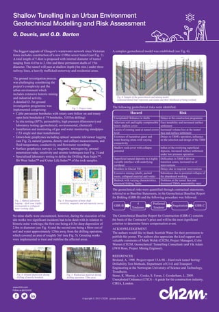
Shallow Tunelling in an Urban Environment
Geotechnical Modelling and Risk Assessment
G. Dounis, and G.D. Barton
The biggest upgrade of Glasgow's wastewater network since Victorian
times includes construction of a new £100m sewer tunnel (see Fig. 1).
A total length of 5.4km is proposed with internal diameter of tunnel
ranging from 4.65m to 2.10m and three permanent shafts of 15m
diameter. The tunnel will pass at shallow depth (4m min.) under three
railway lines, a heavily trafficked motorway and residential areas.
The ground investigation process
was challenging considering the
project’s complexity and the
urban environment which
includes extensive historic mining
and industrial activity.
A detailed £1.5m ground
investigation programme was
implemented comprising:
• Cable percussion boreholes with rotary core follow on and rotary
open hole boreholes (179 boreholes, 5,035m drilling)
• In situ testing (SPTs, permeability, high pressure dilatometer) and
laboratory testing (geotechnical, environmental, chemical)
• Installation and monitoring of gas and water monitoring standpipes
(133 single and dual installations)
• Down-hole geophysics including optical/ acoustic televiewer logging
(see Fig. 2), natural gamma, density and calliper measurements, and
fluid temperature, conductivity and flowmeter recordings
• Surface geophysics surveys i.e. magnetic, microgravity, ground
penetration radar, resistivity and seismic techniques (see Fig. 3) and
• Specialised laboratory testing to define the Drilling Rate Index™,
Bit Wear Index™ and Cutter Life Index™ of the rock samples.
No mine shafts were encountered, however, during the execution of the
site works two significant incidents had to be dealt with in relation to
historic mine workings; the first one being a 0.5m deep depression of
2.0m in diameter (see Fig. 4) and the second one being a blow-out of
soil and water approximately 120m away from the drilling operation,
which covered an area of roughly 5m² (see Fig. 5). Grouting works
were implemented to treat and stabilise the affected areas.
A complex geotechnical model was established (see Fig. 6).
The geotechnical risks were quantified through contractual statements,
referred to as Baseline Statements, in the Geotechnical Baseline Report
for Bidding (GBR-B) and the following procedure was followed:
The Geotechnical Baseline Report for Construction (GBR-C) consists
the basis of the Contractor’s price and will be the most significant
criterion to determine future compensation event.
ACKNOWLEDGEMENT
The authors would like to thank Scottish Water for their permission to
publish this poster. The authors also appreciate the kind support and
valuable comments of Mark Welsh (CH2M, Project Manager), Colin
Warren (CH2M, Geotechnical/ Tunnelling Consultant) and Vik Adam
(JWH Ross, Project Mining Engineer).
REFERENCES
Bruland, A. 1998. Project report 13A-98 – Hard rock tunnel boring:
Drillability Test Methods, Department of Civil and Transport
Engineering at the Norwegian University of Science and Technology,
Trondheim.
Stone, K. Murray, A. Cooke, S. Foran, J. Gooderham, L. 2009.
Unexploded Ordnance (UXO) – A guide for the construction industry,
CIRIA, London.
GBR-B GBR-C
4
Tenderers
Preferred
Tenderer
Negotiation
Fig. 1. Project route.
Fig. 5. Washed-out material during
drilling operation 120m away.
Fig. 2. Optical televiewer
logging – dark zone (right)
corresponds to collapsed
mine working (left).
Fig. 4. Investigation of mine shaft
– resistivity, magnetic and microgravity survey.
The following geotechnical risks were identified:
Hazard
Unexploded Ordnance in shafts
Boulders in Glacial Till
Alluvium soft and highly compressible
below shallow cover
Extensive mining (shafts, packed
waste, collapsed material and voids)
Bedrock with varying characteristics,
structural folding, faults
Layers of running sand at tunnel crown
level
Existence of hazardous gases and
water bearing strata with varying
connectivity
Superficial natural deposits in a highly
variable interface with underlying
rockhead
Shallow rock cover with collapse
potential
Delays to the construction programme
Delays due to required interventions
Face instability and increased surface
settlement
Subsidence due to potential collapse of
the abandoned working
Problems at the tunnel face and
decreased TBM's penetrability rates
Increased volume loss at the tunnel
face and surface settlement
Delays to TBM's operation, influence
on the selection and design of the TBM
Difficulties in TBM’s drive at
transition zones, increased no of
interventions
Influx of the overlying superficial
deposits, increased surface settlement
under low pressure operation
Risk
Fig. 6. Sample of the geotechnical and mining model.
(coloured dotted lines represent coal seams and their likelihood of being worked)
Fig. 4. Ground depression during
drilling of nearby borehole.