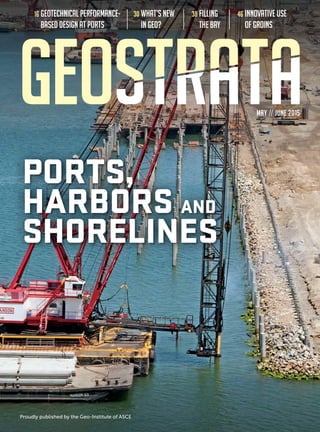
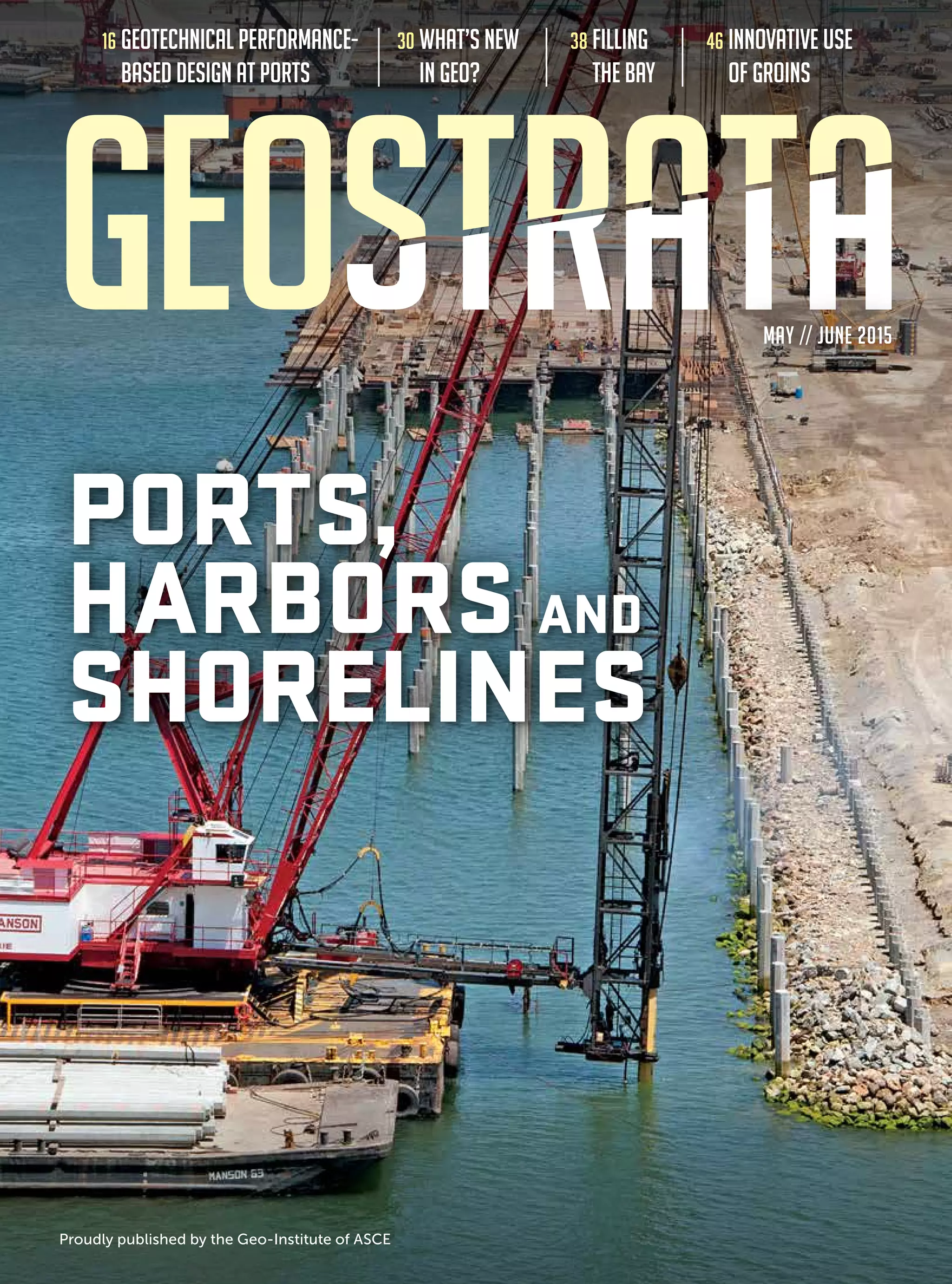
The document is the May/June 2015 issue of GEOSTRATA, a magazine published by the Geo-Institute. The issue features articles on geotechnical performance-based design at ports, recent developments in geotechnical research and practice, projects involving filling bays and using groins, and the use of jet grouting during construction of an offshore wind farm support terminal. It also includes department sections covering news, profiles of geotechnical engineers, student accomplishments, opinions, lessons learned from past engineers, and upcoming events.


![30 GEOSTRATA MAY/JUNE 2015
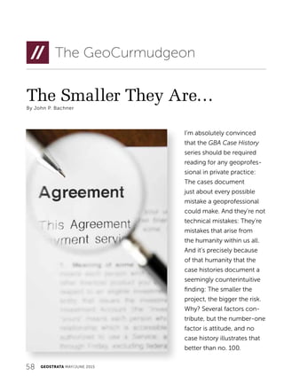
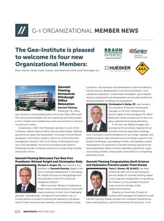
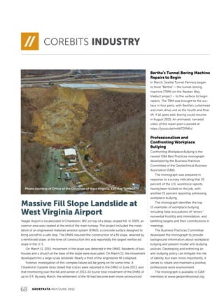
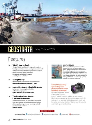
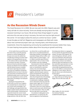
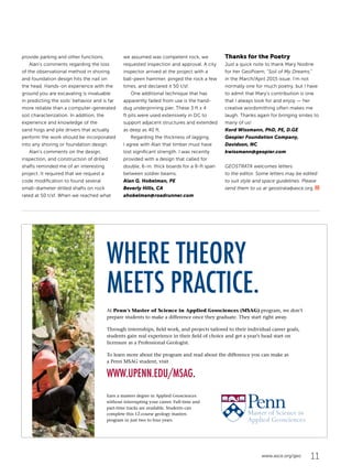
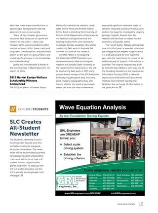
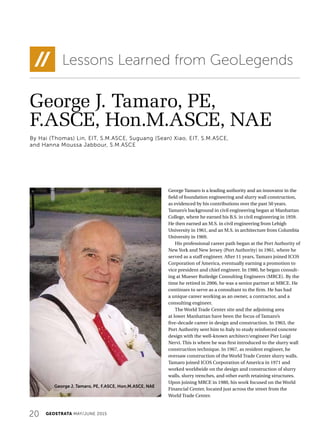
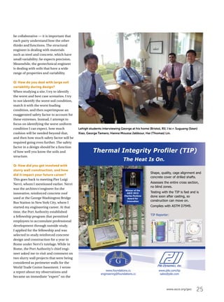
Figure 1. Aerial image of the Oso, WA landslide (courtesy of
the Washington Dept. of Transportation) and elevation differ-
ences based on pre- and post-event lidar surveys (Keaton et
al. 2014) [NSF-sponsored GEER].
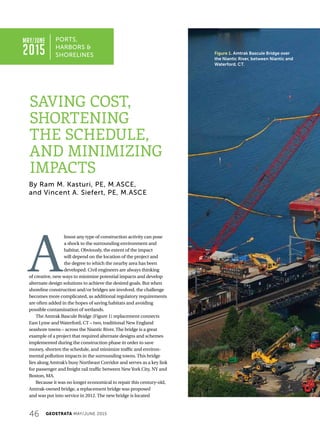
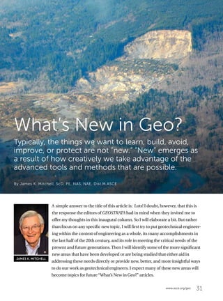
I’m pleased to announce the launch
of a new feature in GEOSTRATA:
“What’s New in Geo?” The goal of
this feature is to provide readers a
broad perspective of recent devel-
opments in research and practice
within the field of geotechnics
that can foretell the future of our
profession. As the boundaries of
our field and the tools at our dis-
posal continually expand to meet
present and future challenges,
it’s important that information be
readily available from a reliable
source. The geotechnical solutions at the forefront include
both evolutions of familiar technologies as well as entirely
new creations borne from collaborations with other fields of
science and engineering.
Just since the start of the 21st century, we have witnessed
the emergence of the field of biosoils, geotechnical
performance monitoring using remote sensing, sustainable
geotechnics, and significant advances in coastal engineering
and ground improvement. Furthermore, the business of geo-
technics is perpetually adapting to the changing economic,
political, and environmental landscape. Major stimuli of change
can emerge from abrupt events like Hurricane Katrina or
gradual phenomena like the aging of our infrastructure.
After evaluating several approaches to achieve our goal,
GEOSTRATA’s Editorial Board decided that we will identify and
solicit a distinguished expert for each piece. Thus, articles will
offer: 1) a short overview of the significance of the subject, 2)
a description of the subject’s state-of-the-art and state-of-
the-practice status, 3) a discussion of recent breakthroughs
and trends, and 4) insights on ways students, researchers,
and practitioners can prepare for the future. As editor of
the “What’s New in Geo?” series, I hope you find value and
inspiration in the discussions, which are slated to appear in two
to three issues annually. I’m honored that Dr. James Mitchell
agreed to write the first article, as I cannot think of another
person better suited for providing the big picture of what’s on
the horizon in our field.
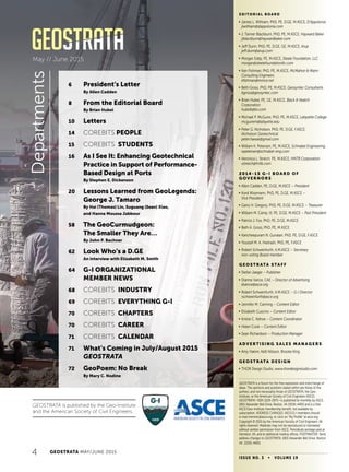
Michael P. McGuire, PhD, PE, M.ASCE
What’s New in Geo? Editor
MICHAEL P. MCGUIRE
What’s New in Geo?](https://image.slidesharecdn.com/geomayjun2015lowres-160621023902/85/Geo-may-jun2015-low-res-32-320.jpg)
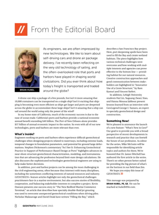
![36 GEOSTRATA MAY/JUNE 2015
oo New and improved laboratory and in-situ testing systems
with programmable control, data acquisition and pro-
cessing capabilities, and more representative model and
centrifuge testing
oo Readily available computer programs for analysis of soil
behavior, at scales ranging from individual particles using
Discrete Element Methods (DEM) to complex 2-D and 3-D
geo-systems at the macro-scale
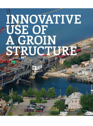
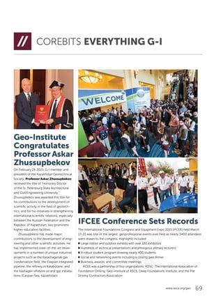
oo Imaging methods that enable direct and indirect observation
and study of soil and rock materials and their deformation
and flow behavior under static and dynamic conditions, at
scales ranging upward from near-atomic size to large areas
where lidar and other methods can reveal details of such
features as faults and ground failure details (Figure 1)
oo Laptops, tablets, and smart phones that enable real-time
documentation, sharing, and retrieval of reconnaissance
information
oo New sensors and instrumentation for acquisition, storage,
and real-time display of data for geo-construction opera-
tions control and documentation
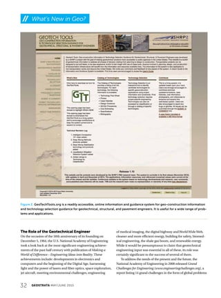
oo Readily available online information and guidance
systems such as GeoTechTools.org (Figure 2), which
provide geo-construction information and technology
selection guidance for geotechnical, structural, and
pavement engineers
Turning now to newer sub-disciplinary areas of geotechnical
engineering and construction, I cite four that I think are at the
forefront and poised to make major contributions both to our
field and in helping us address some of the Grand Challenges:
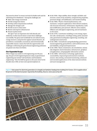
oo Energy Geotechnology has an essential role in many aspects
of fossil fuel energy resource location, recovery, and develop-
ment; in renewable energy development (wind, solar
[Figure 3], tidal); in utilization of nuclear energy; and in
understanding and dealing with associated problems
related to such things as induced seismicity, disposing
and storing of wastes and by-products, environmental
protection, and site restoration. Thermal geotechnics is
assuming an expanded role due to the use of the ground as
both a heat source and heat sink, and for its incorporation
in energy-neutral buildings and other facilities. J. Carlos
Santamarina, in an excellent Commentary in the January/
February 2012 issue of GEOSTRATA, discusses many of the
geotechnical challenges to providing sustainable and envi-
ronmentally acceptable energy supplies in the years ahead.
oo Research on biogeochemical processes in soils and their
applications is opening new doors to a better understanding
of soil properties and behavior.We’re also devising practical
applications, such as new and better methods for con-
taminated site cleanup along with passive uses in ground
strengthening and liquefaction risk mitigation. Editor’s
Note: The next “What’s New in Geo?” article, scheduled for the
September/October 2015 issue of GEOSTRATA, will be written
by Jason DeJong on the subject of biosoils.
oo Sustainability has become a consideration in foundation
engineering, earthwork construction, and ground improve-
ment. Methods are now available to select among alternative
technologies and construction methods using criteria that
compare their quantities of embodied energy and green-
house gas emissions in addition to project performance
requirements and cost.
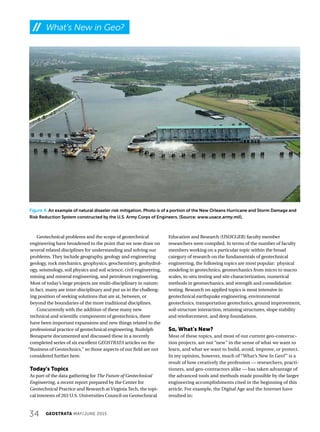
oo Considerations of risk,reliability,and uncertainty are
becoming ubiquitous in geotechnical engineering. They
were the theme of the July/August 2014 issue of GEOSTRATA.
Uncertainty enters virtually every aspect of our work: from
problem definition, site characterization, and hazard
estimation and mitigation (Figure 4), through analysis,
design, construction, and prediction of performance. Efforts
to better quantify and reduce uncertainty as well as define,
communicate, and incorporate risk into decision making will
continue as major focus areas of geotechnical engineering.
I look forward to learning more about how these new
scientific and technological understandings and tools will help
us to grow and strengthen the fabric of the total discipline that
we call geotechnical engineering.
A Final Caveat
While all these new things enable us to do our work smarter,
faster, better, and with improved understanding of the
materials with which we work, there is one vital, but not so
new component of successful geotechnical engineering that
is now more important than ever before: that, of course, is
sound engineering judgment. Despite all the new tools, data
and information sources, computational aids, and guidance
documents, soils and rocks still come in many forms. Their
properties may change with time and environment, the
boundaries are usually uncertain, no two projects are ever
the same, and surprises often lie beneath the surface. A vast
amount of information on almost any topic is now only a
mouse click away; however, the underlying assumptions
and operational details of our new tools and computational
details are often not transparent. Today’s computers cannot
determine whether information is correct or relevant.
Therefore, it is and will always be our responsibility to ensure
that all elements of what we conclude, recommend, and
undertake pass the test of reasonableness.
j JAMES K. MITCHELL, ScD., PE, NAS, NAE, DIST.M.ASCE, is a
University Distinguished Professor Emeritus at Virginia Tech and
a consulting geotechnical engineer. From 1958 to 1994, he was
on the CEE faculty at the University of California, Berkeley. His
research and consulting activities have focused on soil behavior,
soil stabilization, and ground improvement. He can be reached
at jkm@vt.edu.
What’s New in Geo?](https://image.slidesharecdn.com/geomayjun2015lowres-160621023902/85/Geo-may-jun2015-low-res-38-320.jpg)