Fundamentals Of Software Engineering Engineering Handbook 1st Edition Rajat Gupta
Fundamentals Of Software Engineering Engineering Handbook 1st Edition Rajat Gupta
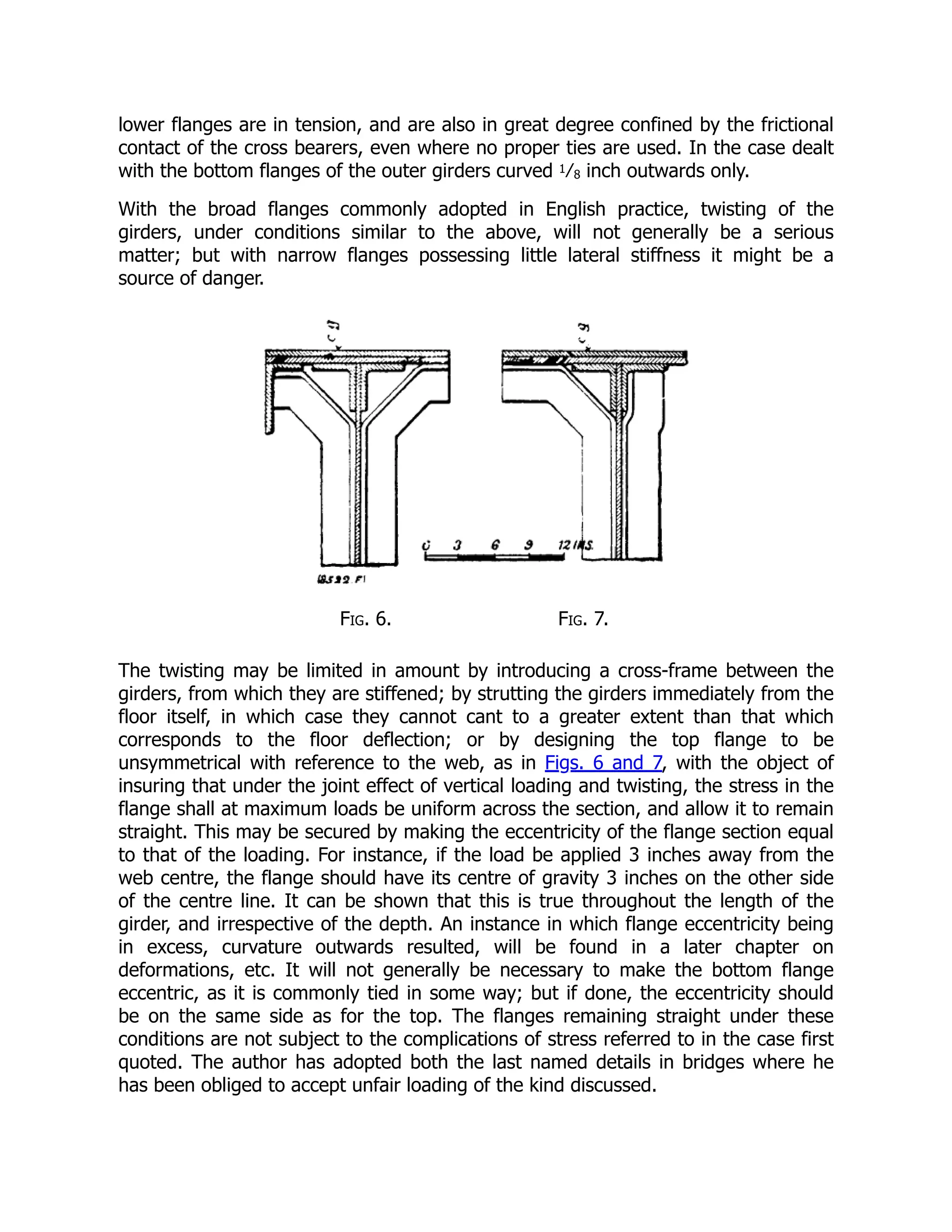
Fundamentals Of Software Engineering Engineering Handbook 1st Edition Rajat Gupta
Fundamentals Of Software Engineering Engineering Handbook 1st Edition Rajat Gupta
Fundamentals Of Software Engineering Engineering Handbook 1st Edition Rajat Gupta
1.
Fundamentals Of SoftwareEngineering Engineering
Handbook 1st Edition Rajat Gupta download
https://ebookbell.com/product/fundamentals-of-software-
engineering-engineering-handbook-1st-edition-rajat-gupta-36522684
Explore and download more ebooks at ebookbell.com
2.
Here are somerecommended products that we believe you will be
interested in. You can click the link to download.
Fundamentals Of Software Engineering Fifth Edition Rajib Mall
https://ebookbell.com/product/fundamentals-of-software-engineering-
fifth-edition-rajib-mall-34776538
Fundamentals Of Software Engineering 2nd Carlo Ghezzi Mehdi Jazayeri
https://ebookbell.com/product/fundamentals-of-software-
engineering-2nd-carlo-ghezzi-mehdi-jazayeri-4068510
Fundamentals Of Software Engineering 4th Ipm International Conference
Fsen 2011 Tehran Iran April 2022 2011 Revised Selected Papers 1st
Edition Joostpieter Katoen Auth
https://ebookbell.com/product/fundamentals-of-software-
engineering-4th-ipm-international-conference-fsen-2011-tehran-iran-
april-2022-2011-revised-selected-papers-1st-edition-joostpieter-
katoen-auth-4141858
Fundamentals Of Software Engineering Third Ipm International
Conference Fsen 2009 Kish Island Iran April 1517 2009 Revised Selected
Papers 1st Edition J C M Baeten
https://ebookbell.com/product/fundamentals-of-software-engineering-
third-ipm-international-conference-fsen-2009-kish-island-iran-
april-1517-2009-revised-selected-papers-1st-edition-j-c-m-
baeten-4141860
3.
Fundamentals Of SoftwareEngineering 5th International Conference Fsen
2013 Tehran Iran April 2426 2013 Revised Selected Papers 1st Edition
Jurriaan Rot
https://ebookbell.com/product/fundamentals-of-software-
engineering-5th-international-conference-fsen-2013-tehran-iran-
april-2426-2013-revised-selected-papers-1st-edition-jurriaan-
rot-4334124
Fundamentals Of Software Engineering 6th International Conference Fsen
2015 Tehran Iran April 2224 2015 Revised Selected Papers 1st Edition
Mehdi Dastani
https://ebookbell.com/product/fundamentals-of-software-
engineering-6th-international-conference-fsen-2015-tehran-iran-
april-2224-2015-revised-selected-papers-1st-edition-mehdi-
dastani-5236560
Fundamentals Of Software Engineering 7th International Conference Fsen
2017 Tehran Iran April 2628 2017 Revised Selected Papers 1st Edition
Mehdi Dastani
https://ebookbell.com/product/fundamentals-of-software-
engineering-7th-international-conference-fsen-2017-tehran-iran-
april-2628-2017-revised-selected-papers-1st-edition-mehdi-
dastani-6790870
Fundamentals Of Software Engineering 4th Ed Rajib Mall
https://ebookbell.com/product/fundamentals-of-software-
engineering-4th-ed-rajib-mall-10414058
Fundamentals Of Software Engineering 8th International Conference Fsen
2019 Tehran Iran May 13 2019 Revised Selected Papers 1st Ed 2019
Hossein Hojjat
https://ebookbell.com/product/fundamentals-of-software-
engineering-8th-international-conference-fsen-2019-tehran-iran-
may-13-2019-revised-selected-papers-1st-ed-2019-hossein-
hojjat-10800644
5.
engineering handbook RajatGupta
First Edition
2019
SOFTWARE
SOFTWARE
SOFTWARE
Engineering
Engineering
Engineering
FUNDAMENTALS OF
FUNDAMENTALS OF
FUNDAMENTALS OF
6.
Contents
C H AP T E R . 1 . INTRODUCTION TO SOFTWARE ENGINEERING
1.1 INTRODUCTION 1
1.2 SOFTWARE CLASSES 2
1.3 TYPES OF SOFTWARE 2
1.3.1 System Software 2
1.3.2 Application Software 2
1.3.3 Utility Software 2
1.4 ROLE OF SOFTWARE 3
1.5 WHAT IS A GOOD SOFTWARE ? 4
1.6 PROGRAM VS. SOFTWARE 4
1.7 SOFTWARE CAN BE VIEWED AS A PRODUCT. HOW ? 5
1.8 LIMITATIONS OF SOFTWARE 6
1.9 SOFTWARE CRISIS 6
1.10 SOFTWARE MYTHS 7
1.10.1 Management myths 7
1.10.2 Customer myths 7
1.10.3 Practitioner’s myths 7
1.11 WHY SOFTWARE NEEDS TO BE TREATED IN
AN ENGINEERED WAY ? 8
1.12 WHAT IS SOFTWARE ENGINEERING ? 8
1.13 SOFTWARE ENGINEERING ACTIVITIES, SKILLS
AND CHALLENGES 9
1.14 SOFTWARE ENGINEERING COMPONENTS 10
1.14.1 Systems Engineering Approach 10
1.14.2 Development Engineering Approach / Methodology 10
1.14.2.1 SSAD and OOSAD 11
1.15 WHAT IS A SOFTWARE PROCESS ? 13
1.16 SOFTWARE DEVELOPMENT PROCESS MODELS 13
1.17 SOFTWARE DEVELOPMENT LIFE CYCLE : (SDLC) 14
1.18 MODERN SOFTWARE DEVELOPMENT 14
SUMMARY 15
EXERCISES 16
C H A P T E R . 2 . SOFTWARE DEVELOPMENT LIFE CYCLE (SDLC)
2.1 DEFINITION 17
2.2 OBJECTIVES OF SDLC : SDLC 17
2.3 PHASES OF SDLC 17
2.4 DIAGRAMMATIC REPRESENTATION OF SOFTWARE LIFE CYCLE 18
2.4.1 User / Stakeholder’s requirements 18
2.4.2 Feasibility study 19
2.4.3 Requirement analysis and specification 19
2.4.4 Design 19
2.4.5 Coding 20
2.4.6 Testing 20
2.4.7 Certification 20
7.
2.4.8 Implementation 20
2.4.9Maintenance and review 20
2.4.10 Special phases 20
SUMMARY 22
EXERCISE 22
C H A P T E R . 3 . SOFTWARE PROCESS MODEL
3.1 INTRODUCTION 23
3.2 CATEGORIES OF SOFTWARE PROCESS MODELS 24
3.3 THE WATERFALL MODEL 24
3.3.1 Systemengineering 25
3.3.2 Requirement analysis 25
3.3.3 Design phase26
3.3.4 Coding 27
3.3.5 Testing 27
3.3.6 Maintenance 27
3.3.6 Advantages 28
3.3.7 Disadvantages 28
3.4 PROTOTYPING MODEL 28
3.4.1 Reasons for using prototyping model 29
3.4.2 Type of prototyping 29
3.4.3 Evolutionary prototyping 29
3.4.4 Throwaway prototyping 30
3.4.5 Rapid prototyping techniques 31
3.5 THE RAPID APPLICATION DEVELOPMENT (RAD) MODEL 32
3.5.1 Process of the RAD 33
3.5.2 Advantages of RAD model 34
3.6 THE NEED FOR EVOLUTIONARY MODELS 34
3.7 THE INCREMENTAL MODEL 35
3.7.1 Advantages 35
3.7.2 Disadvantages 36
3.8 SPIRAL MODEL 36
3.9 COMPONENT ASSEMBLY MODEL 37
3.9.1 Advantages 38
3.9.2 Disadvantages 38
3.10 THE CONCURRENT DEVELOPMENT MODEL 39
3.10.1 Advantages 39
3.11 THE FORMAL METHODS MODEL 40
3.11.1 The merits of this model are given below 40
3.11.2 The demerits of this model are listed below 40
3.12 FORTH GENERATION TECHNIQUES (4GT) 40
3.13 COMPARISON AND SUITABILITY OF SOFTWARE
LIFECYCLE MODELS 41
3.14 SELECTION OF A LIFECYCLE MODEL 43
3.14.1 Characteristics of requirements 43
3.14.2 Status of development team 44
3.14.3 Involvement of users 44
3.14.4 Type of project and associated risk 45
SUMMARY 45
EXERCISE 46
8.
C H AP T E R . 4 . FEASIBILITY STUDY
4.1 INTRODUCTION 48
4.2 SOFTWARE PROJECT MANAGEMENT 48
4.3 ROLE OF PROJECT MANAGER 48
4.4 ROLE OF SYSTEM ANALYST 49
4.5 PROJECT MANAGEMENT DIFFICULTIES 49
4.6 SOFTWARE PROEJCT PLANNING 50
4.7 SOFTWARE PROJECT MANAGEMENT PLAN (SPMP) 50
4.8 SOFTWARE PROJECT SCHEDULING 53
4.8.1 Project scheduling activities 53
4.8.2 Software project scheduling techniques 54
4.8.2.1 Work Breakdown structure (WBS) 54
4.8.2.2 Activity chart / Network 55
4.8.2.3 CPM and PERT 59
4.8.2.4 GANTT Charts 76
4.9 SOFTWARE PROJECT ESTIMATION 79
4.9.1 Software metrics in project estimation 80
4.9.2 Types of software metrics 81
4.9.3 Qualities of software metrics 81
4.9.4 Product metrics 82
4.9.4.1 Lines of codes (LOCs) 82
4.9.4.2 Function Points (FPs) 83
4.9.4.3 Feature Point metrics 87
4.9.5 Software project estimation techniques 87
4.9.6 Cylcomatic complexity 98
4.9.6.1 Program Control Flow Graph (CFG) 99
4.9.6.2 Advanages of cyclomatic compelxity 100
4.9.6.3 Disadvantages 100
4.10 ESTIMATION ON STAFFING 104
4.10.1 Rayleigh’s model 104
4.11 TEAM STRUCTURE 108
4.12 SOFTWATE RISK MANAGEMENT 109
4.12.1 Risk management activities 110
4.12.2 Risk control 112
SUMMARY 113
EXERCISE 113
C H A P T E R . 5 . REQUIRMENT ENGINEERING
5.1 INTRODUCTION 116
5.2 PROBLEM ANALYSIS AND PRODUCT DESCRIPTION 117
5.3 REQUIREMENTS ENGINEERING (RE) 117
5.3.1 Requirements elicitation 118
5.3.2 Requirements analysis 120
5.3.3 Requirements sepcification 120
5.3.4 Modeling the system 120
5.3.5 Requirements validation 121
5.3.6 Requirements management 121
9.
5.4 CONDUCTING AREQUIREMENTS STUDY 121
5.5 FACILITATED APPLICATION SPECIFICATION TECHNIQUES (FAST) 122
5.6 IMPACT OF PROTOTYPING ON REQUIREMENTS 123
5.7 USES OF THE SRS 124
5.8 WHAT OUGHT TO BE INCLUDED IN THE SRS ? 125
5.8.1 Behavioral Requirements 125
5.8.2 Non-behavioral Requirements 125
5.9 EXCLUSION OF PROJECT REQUIREMENTS FROM SRS 125
5.10 EXCLUSION OF DESIGN FROM SRS 125
5.11 EXCLUSION OF PRODUCT ASSURANCE PLANS FROM SRS 125
5.12 ATTRIBUTES OF HIGH QUALITY SRS 126
5.13 GENERAL FORMAT OF A SRS 128
5.14 STANDARDS IN SRS 128
5.15 AN APPROVED FORMAT FOR SOFTWARE REQUIREMENTS
SPECIFICATIONS(S.R.S) 136
5.16 SRS : ALIVE EXAMPLE 141
SUMMARY 155
EXERCISES 156
C H A P T E R . 6 . SOFTWARE DESIGN & CODING
6.1 INTRODUCTION TO SOFTWARE DESIGN 157
6.2 DEFINITIONS 157
6.3 DESIGN PROCESS 158
6.3.1 Interface Design 159
6.3.2 Architectural Design 159
6.3.2.1 Assessment of Architectural Design 160
6.3.3 Detailed Design 161
6.4 DESIGN CHARACTERISTICS 161
6.5 CRITERIA FOR QUALITY DESIGN 161
6.6 PRINCIPLES OF DESIGN 162
6.6.1 Modularity and Partitioning 162
6.6.2 Coupling 163
6.6.3 Cohesion 166
6.6.4 Span of Control 170
6.6.5 Module Size 170
6.6.6 Shared Use 171
6.7 IEEE RECOMMENDED DDS [DESIGN DOCUMENT SPECIFICATION]
OR SDD [SOFTWARE DESIGN DOCUMENT] 171
6.7.1 Content description of SDD / DDS 172
6.7.2 Organisation of SDD 174
6.8 USER INTERFACE DESIGN 175
6.8.1 Graphical User Interface (GUI) vs.
Character- based User Interface (CUI) 176
6.8.2 Classification of User Interface 178
6.8.3 Qualities of good User Interface Design (UID) 179
6.8.4 User Interface Design Principle 180
6.8.5 Elements for user interface Design 180
6.8.6 Graphical user interface 181
10.
6.8.6.1 Elements ofGUI design 182
6.8.6.2 Window Management System (WMS) 187
6.8.6.2.1 X-Window system 189
6.9 SOFTWARE DESIGN METHODS 195
6.9.1 Function-Oriented Design 196
6.9.2 Data Structure Based Design 197
6.9.2.1 Jackson Systems Development 197
6.9.2.2 Warnier-Orr’System Design 199
6.9.3 Object-Oriented Design Methods 201
6.9.3.1 Benefits of OOD 202
6.9.3.2 Types of OOD Methods 202
6.9.4 Reuse-Based Design Methods 203
6.9.5 Criteria for selecting a software Design Method 203
6.10 INTRODUCTION TO SOFTWARE CODING 204
6.10.1 Coding Standards 204
6.10.2 Coding Conventions 205
6.10.3 Programming Style 207
6.10.3.1 Importance of Programming Style 207
6.10.3.2 General Program Style 207
6.10.3.3 Good Programming Style 208
6.10.3.4 Good Programming StyleAids 208
6.10.4 System Verification 209
6.10.4.1 Program Testing 209
6.10.4.2 Reviews of Design and Code 210
6.10.5 Code Inspections 210
6.10.5.1 Code Inspection Process 211
6.10.5.2 Checklist for Code Inspections 212
6.10.5.3 Benefits of Code Inspections 213
6.10.6 Code Reviews and Walkthroughs 213
6.10.6.1 Rules for Code Reviews and Walk-throughs 214
6.10.6.2 Benefits of Code Reviews and Walkthroughs 214
6.10.6.3 Limitations of Code Reviews and Walkthroughs 214
6.10.7 Coding Tools215
6.10.8 Documents Generated From Coding 215
SUMMARY 215
EXERCISE 216
C H A P T E R . 7 . SOFTWARE TESTING
7.1 INTRODUCTION 219
7.2 TESTING AND SDLC : AN INTER-RELATIONSHIP 219
7.3 TESTING TERMINOLOGIES 220
7.4 DEFINITIONS OF SOFTWARE TESTING 221
7.5 PRINCIPLES OF TESTING 221
7.6 OBJECTIVES OF TESTING 222
7.7 LEVELS OF TESTING 222
7.7.1 Unit testing 223
7.7.2 Integration testing / Interface testing 225
7.7.3 System testing 230
7.8 BLACK BOX (FUNCTIONAL) TESTING 231
11.
7.9 WHITE BOXTESTING / STRUCTURAL TESTING 232
7.10 STATIC TESTING STRATEGIES : 235
7.11 FORMAL TECHNICAL REVIEWS 236
7.12 DEBUGGING 236
7.12.1 Debugging process 237
7.13 SPECIAL SYSTEM TESTS 238
SUMMARY 239
EXERCISES 239
C H A P T E R . 8 . SOFTWARE CERTIFICATION
8.1 INTRODUCTION 240
8.2 VERIFICATION AND VALIDATION 241
8.3 SOFTWARE QUALITY ASSURANCE 241
8.3.1 SQA objectives 242
8.3.2 SQA plan 242
8.4 SOFTWARE QUALITY 243
8.4.1 Classification of software quality 243
8.4.2 Software quality attributes 243
8.4.3 McCall’s quality factors 244
8.4.3.1 Product operation quality factors 244
8.4.3.2 Product revision factors 245
8.4.3.3 Product transition quality factors 245
8.4.4 Criteria for software quality 245
8.4.5 Quality representation 245
8.4.6 Importance of software quality 246
8.5 CAPABILITY MATURITY MODEL (SEI - CMM) 246
8.6 INTERNATIONAL STANDARD ORGANISATION (ISO) 249
8.6.1 Need of ISO certification for software industry 249
8.6.2 Steps for ISO 9000 certification 249
8.6.3 Benefits of ISO-9000 certification 250
8.6.4 Uses of ISO 250
8.6.5 Comparison between ISO 9000 certification and SEI-CMM 251
8.6.6 Classification of failures 252
8.6.7 Limitation of ISO 9000 certification 252
8.7 RELIABILITY ISSUES 252
8.7.1 Software reliability specification 253
8.7.2 Reliability terminologies 253
8.7.3 Reliability metrics 253
8.7.4 Measurement of Reliability and Availability 254
8.7.5 Reliability growth modelling 256
8.8 PERSONAL SOFTWARE PROCESS 258
8.8.1 PSP planning258
8.9 SIX SIGMA 259
8.9.1 Objectives 259
SUMMARY 260
EXERCISES 260
12.
C H AP T E R . 9 . SOFTWARE MAINTENANCE
9.1 INTRODUCTION 262
9.2 NEED FOR SOFTWARE MAINTENANCE 262
9.3 CATEGORIES OF MAINTENANCE 263
9.4 CHALLENGES IN MAINTENANCE 264
9.5 SOLUTION TO MAINTENANCE CHALLENGES 265
9.6 MAINTENANCE PROCESS 266
9.7 MAINTENANCE MODELS 267
9.7.1 Build and Fix model 267
9.7.2 Iterative enhancement model 268
9.7.3 Reuse - oriented model 269
9.7.4 Boehm’s model 270
9.7.5 Taute maintenance model 270
9.8 MAINTENANCE COST ESTIMATION 272
9.9 CHARACTERISTICS OF SOFTWARE EVOLUTION 273
9.10 SOFTWARE CONFIGURATION MANAGEMENT 276
9.10.1 Version and Releases 277
9.10.2 Version and Release management 278
9.10.3 What is Milestone and Deliverable ? 278
9.10.4 Software Configuration Management activities 278
9.11 CHANGE CONTROL PROCESS 282
SUMMARY 284
EXERCISES 284
C H A P T E R . 10 . SOFTWARE RE-ENGINEERING
10.1 INTRODUCTION 286
10.2 SOFTWARE RE-ENGINEERING PROCESS MODEL 287
10.2.1 Inventory analysis 288
10.2.2 Document restructuring 288
10.2.3 Reverse engineering 288
10.2.4 Code re-structuring 289
10.2.5 Data re-structuring 289
10.2.6 Forward engineering 289
10.3 ADVANTAGES OF SOFTWARE RE-ENGINEERING 289
10.4 REVERSE, FORWARD AND RE-ENGINEERING :
A COMPARATIVE STUDY 290
10.5 IMPORTANCE OF REVERSE ENGINEERING 290
10.6 REVERSE ENGINEERING PROCESS 290
10.7 LEVELS OF REVERSE ENGINEERING 291
10.7.1 Redocumentation 292
10.7.2 Structural redocumentation 292
10.7.3 Design Recovery 292
10.8 REVERSE ENGINEERING TOOLS 292
SUMMARY 293
EXERCISE 293
13.
C H AP T E R . 11 . COMPUTER AIDED SOFTWARE ENGINEERING
11.1 INTRODUCTION 294
11.2 LEVELS OF CASE 295
11.3 ARCHITECTURE OF CASE ENVIRONMENT 295
11.3.1 User Interface / Interface Generator 296
11.3.2 Tools Management Services (Tools Set) 296
11.3.3 Object Management System (OMS) 296
11.3.4 Repository 296
11.4 BUILDING BLOCKS FOR CASE 297
11.5 CASE SUPPORT IN SOFTWARE LIFE CYCLE 297
11.6 OBJECTIVES OF CASE 299
11.7 CASE REPOSITORY 300
11.8 CHARACTERISTICS OF CASE TOOLS 302
11.9 CLASSIFICATION OF CASE TOOLS 302
11.10 CATEGORIES OF CASE TOOLS 303
11.11 ADVANTAGES OF CASE TOOLS 305
11.12 DISADVANTAGES OF CASE TOOLS 305
SUMMARY 306
EXERCISES 306
C H A P T E R . 12 . UNIFIED MODELING LANGUGE
12.1 INTRODUCTION 307
12.2 MODEL 308
12.3 THE UML 308
12.4 UML ARCHITECTURE 310
12.5 UML FOUNDATIONS 311
12.6 RULES OF THE UML 313
12.7 COMMON MECHANISMS IN UML 313
12.8 USE CASE DIAGRAM 314
12.9 CLASS DIAGRAM 316
12.9.1 Relationship in class Diagram 317
12.9.2 Extensibility mechanisms 322
12.9.3 Example of UML Class Diagram 324
12.9.4 Meta Model 324
12.10 INTERACTION DIAGRAMS 325
12.10.1 Sequencediagrams 325
12.10.2 Collaboration diagrams 327
12.11 STATE-CHART DIAGRAM 328
12.12 ACTIVITY DIAGRAM 330
12.13 OBJECT DIAGRAM 332
12.14 IMPLEMENTATION DIAGRAMS 332
12.14.1 Component Diagram 332
12.14.2 Deployment Diagram 333
12.15 PACKAGES AND MODEL MANAGEMENT 334
12.16 OBJECT CONSTRAINT LANGUAGE 336
12.17 MODELING PATTERNS & FRAMEWORKS IN UML 336
14.
12.17.1 Patterns 336
12.17.2Frameworks 338
12.18 UML COMPATIBILITY 339
SUMMARY 340
EXERCISE 340
C H A P T E R . 13 . OBJECT ORIENTED SOFTWARE ENGINEERING
13.1 INTRODUCTION 341
13.2 OBJECT ORIENTED TERMINOLOGIES 342
13.3 OBJECT ORIENTED SDLC
(SOFTWARE DEVELOPMENT LIFE CYCLE) 343
13.3.1 Objectives of Object Oriented SDLC 343
13.3.2 The Software Development Process 345
13.3.2.1 Object-Oriented Requirements Analysis (OORA) 346
13.3.2.2 Object-Oriented Analysis (OOA) 346
13.3.2.3 Object-Oriented Design (OOD) 347
13.3.2.4 Object-Oriented Programming (OOP) 347
13.4 MERITS OF OBJECT ORIENTED SOFTWARE 354
13.5 DEMERITS OF OBJECT ORIENTED SOFTWARE 354
13.6 DIFFERENCES BETWEEN OOA AND OOD 354
13.7 OOPS PROGRAMMING LANGUAGES 355
SUMMARY 357
EXERCISE 357
C H A P T E R . 14 . SOFTWARE & TOOLS
14.1 INTRODUCTION 358
14.2 ANALYSIS TOOLS 359
14.3 DESIGN TOOLS 359
14.4 DEVELOPMENT TOOLS 359
14.5 TOOLS FOR SPECIAL PURPOSES 360
14.5.1 Tools for Documenting procedure and Decision making 360
14.5.2 Tools for Data Flow strategy or Data Flow Analysis 363
14.5.3 Tools for Proto-typing 396
SUMMARY 398
EXERCISE 398
BIBLIOGRAPHY 399
ppp
15.
1.1 INTRODUCTION
Computers; Amazingmachines !
We are living and breathing in the computer age and the computer has gradually become
such a basic necessity of life that it is tough to imagine the life without it.
Computers are affecting every sphere of our life, in government, business, education,
entertainment, defence, medical science, space, research, weather forecast, legal practice,
even in our personal and day-to-day life.
* To think of anything without computer is meaningless.
A computer system can be viewed as a flexible electronic / mechanical device, responds
inputs (data), processes and produces outputs (information).
Basically computer system is framed using the following elements.
* Processing unit
* Memory unit
* Input unit
* Output unit.
* Program.
Now, you must be wandering, what is so special about this machine that people from
diversified fields can use it so flexibly for entirely different functions ?
The answer is that the computer is programmable i.e. it all depends upon what program it
is using for performing a particular function.
What is a program ? In very simple language we can say that a “program is a set of
instructions tells the computer what to do.”
A computer system can be broadly disintegrated into two parts.
* the hardware part
* the software part.
è Software runs the Hardwares
Software is a general term, which is used to described a set of instruction (more precisely
programs) written with the help of some predefined/planned format / procedures.
Software may be a program or a set of programs.
1
C
H
A
P
T
E
R
Introduction to software
Engineering
16.
2 Fundamentals ofSoftware Engineering
The importance of software can be viewed through an example, say human brain vs
human body.
All parts of human body are activated / controlled by the human brain with predefined
instructions (program) fed into it.
The attitude / activities and response of a person are truly based on the “mantras” (i.e. the
software) given to the human brain.
è The change in Software influences Hardwares
1.2 SOFTWARE CLASSES
It is classified into two categories.
l Generic software
l Customised software
Generic software is designed for a wide range of market whose requirements are common,
stable and well understood.
Example - Operating system software
Customised (Bespoke product) software is designed for a customer where domain,
environment and requirements are unique to the customer only.
Example - Application software :
1.3 TYPES OF SOFTWARE
Software generally of three types :
- System software
- Application software
- Utility software
1.3.1 System Software
This consists of alltheprograms,languages anddocumentationssuppliedbythemanufacturer
of the computer system for its exclusive use.
Example - Operating system, BIOS programs, Platform oriented software, It also comes
under system software
Example - Interpreter, Compiler.
1.3.2 Application Software
These programs are developed by professional groups for some specific application /
functions. These are also called user-based software.
Example - Pay roll system, Banking software.
Embedded software.
1.3.3 Utility Software
This may be considered as an application software / system support software which is
very often used in the development of wide range of programs.
Example - MS-Office, Compilers, Interpreters, Debugger etc.
17.
3
Software Engineering
1.4 ROLEOF SOFTWARE
The key role of software is to perform tasks for the user by activating and controlling the
computer hardwares.
It can be shown in the following fig. 1.1
User-hardware interfacing through software
Software applications are categorised into five types for convenience. They are system
software, business software, design and scientific software, embedded software and
artificial intelligence software.
Software application category
System software enables and provide services to software applications loaded on the
computer system. It regulates the system perforance and helps to run user-initiated
applications.
Fig. - 1.1
Fig. - 1.2
18.
4 Fundamentals ofSoftware Engineering
Business software can be a generic product or customised product. Some are common to
all industries and some deal with industry specific information processing requirements.
Design / scientific softwares deal with processing requirements in their specific field.
These Softwares service the need of drawing, drafting, modeling, load calculation, building
planning and designing using CAD/CAM, analysis of engineering data, statistical data
for interpretation and decision making.
Embedded softwares are used to perform specific funtion under control conditions and
further embedded into hardware as a part of large system. Ex. in Robotics
Artificial Intelligence software (AI) uses non-numeric algorithms, which use the data
and information generated in the system to solve complex problems.
1.5 WHAT IS A GOOD SOFTWARE ?
A software can have number of attributes, which together will decide whether it is a good or
bad one. The definition of a good software varies with respect to the person who evaluates it.
l The customer will decide on the basis of the cost-effectiveness of the software.
l The user group will consider it’s usability and reliability.
l The software engineer will look at its maintainability and efficiency.
The measure of good software is the customer satisfaction, cost and budget constraint
fulfillment. Customer satisfaction depends on the degree to which customer requirements
and expectations have been met.
The minimum essential attributes of a good software are maintainability, dependability,
efficiency and usability.
Table- 1.1 : Generic comparison of software with hardware.
Generation Hardwares Softwares
1st Generation
1944 - 1955
Vaccum tubes Machine language
2nd Generation-1956 Transistors Symbolic language
3rd Generation
1964-1970
Integrated circuit High level language
FORTRAN, ALGOL. etc.
4th Generation
1971-1990
Large scale
Integrated circuits.
PLI Basic
PASCALS etc.
5th Generation
1990 +
Very Large Scale
Integration
C, C++, Visual Basic,
Fox-pro, DBMS, Prolog,
LISP etc.
è The rate of advancement in software is more as compare to hardware
1.6 PROGRAM VS. SOFTWARE
People say “program is a software and software is a program or set of programs”. So how
to distinguish ?
19.
5
Software Engineering
Program Software
Programvs software
Simple, program comes under the software category or program is a subset of software.A
program can be viewed as
- a set of instructions written for a specific task by individuals.
- small in size and limited functionality.
- it does not hold all the properties of what actually it is intended for.
[size, portability, compatibility, entertaining wide range of inputs, user friendly etc. and lot
more...]
è Program = source code + object code
A software is a broad sense of developing programs that satisfies the criteria like
user friendly
portable
maintainable
fitsto wide range of environments
error / risk free
cost effective etc.
-
-
-
-
-
-
Software consists not only program codes but also of all associated documents (design,
testing operating procedures which includes user manuals and operational manuals.)
è Software = program + documentation + operating procedures
1.7 SOFTWARE CAN BE VIEWED AS A PRODUCT. HOW ?
A product (consumable) which is available in the market is exhausted for the users.
The demand of a product is based on its price, quality, durability. When the demand of the
customers changes w.r.t their taste / use, manufacturers need to modify / redesign these
existing products or to introduce new products time-to-time.
Fig. - 1.3
20.
6 Fundamentals ofSoftware Engineering
Due to the advancement and global use of computer systems in each and every field
(as shown in the generic comparison), the software plays vital role for all the users (End
user, Govt. organisations etc)
1.8 LIMITATIONS OF SOFTWARE
- Software is not scalable.
- It detoriates, but never wears out.
- It’s existence can be felt when it runs.
- Legacy software can not be easily migrated and maintained.
- Software is engineered not manufactured.
- Software is custom built.
Limitations of Software :
Fig. - 1.4
Bath - Tube Curve Software curve
1.9 SOFTWARE CRISIS
The term “Software crisis” refers to a set of problems encountered in the development of
software and to encapsulate all the ills of the software product.
It is also characterised by “an inability to develop software on time, budget and within
the requirements.”
A list of problems and the reasons on software crisis is given below.
Problems :
- Schedule and cost estimates are inaccurate.
- Productivity is not in pace with the demand of customers.
- Quality of the software is poor.
- Communication between the user and developer is measurable.
- Low maintenance.
Reasons :
- There is delay in process or stage (analysis, design, codingand testingetc.) resulting
out of schedule.
Fig. - 1.5
21.
7
Software Engineering
- Noproper methods to estimate a software project.
- No adequate principles of communication between user and developer.
Software crisis counts the problem of :
- Software compatibility
- Portability
- Documentation
- Staffing and Co-ordination
- Maintenance
- Cost effectiveness
- User friendliness
- Availability of bugs
- Software product updation etc.
- Risk containment.
1.10 SOFTWARE MYTHS
These are something like traditional stories / beliefs concern with the use and
development of softwares by the user / developers that affect the way. Myths may appear
to be reasonable statements of facts but may not be sufficiently enough to be implemented.
Some myths are :
1.10.1 Management myths
- We do have books full of standards and principles for building software.
* then, what’s the use of a software manager ?
- It’s late finishing a Software product, just add more programmer to catch up the
project.
* Allas ! it’s not building a house.
- Better to hand over the project to a third party and get relaxed.
* Dream rarely comes true.
1.10.2 Customer myths
- I got money, I can avail it.
* Does it require to peep inside the basket what it contains & what I need ?
- Hey, I purchased the product that will do for me for ever.
* Are you satisfied with a fixed recipe throughout a week ?
- Software is flexible, It can be modified and the change can be accommodated any
time.
* It’s not a magician pocket to get any thing out of it, rather it needs a
framework, additional cost and time.
1.10.3 Practitioner’s myths
- We write a program once, get it to work and relax.
* Do you feel the only responsibility of mother to give birth a child ?
- Developing a program results with a software.
* A house is not a house if it has four walls and a roof.
22.
8 Fundamentals ofSoftware Engineering
1.11 WHY SOFTWARE NEEDS TO BE TREATED IN AN ENGINEERED WAY ?
“Engineering” is a discipline, which is framed with the association of
- People
- Machines
- Resources
- Technology
- Methods.
for manufacturing / making of products as per the user’s need / demand of the market i.e.
- Timely produced
- User friendly
- Economic
- Reliable etc.
As software is a product, it needs to be treated from it’s inception to retirement stage in an
engineered way satisfying all needs of the developers (before, during & after the
development of software product) and the user’s using it.
1.12 WHAT IS SOFTWARE ENGINEERING ?
Software Engineering is a methodology that includes process, methods, tools and
techniques for the manufacturing of a software product which is -
- Timely produced
- User’s friendly
- Reliable
- Cost-effective
- Portable
- Versatile
- Inter-operable
- Maintainable
- Reusable
Software Engineering Definitions :
There are number of definitions of Software Engineering traced by different research
groups, development organisations, software developers etc.
Some of highlighted definitions are noted below.
Fritz Bauer (1969)
Software Engineering is the establishment and use of sound engineering principles in
order to obtain economicallysoftware that is reliable and works efficiently on real machines.
Dennis (1975)
Software Engineering is the application of principles, skills and art to the design and
construction of programs and system of programs.
Boehm (1979)
Software Engineering is the practical of scientific knowledge in the design and
construction of computer programs and the associated documentation required to develop,
operate and maintain them.
23.
9
Software Engineering
Fairley (1985)
SoftwareEngineering is the technological and managerial discipline concerned with
the systematic production and maintenance of software products that are developed and
modified on time and within estimated cost.
IEEE (1991)
Software Engineering is the application of a systematic, disciplined and quantifiable
approach to the development, operation and maintenance of software.
Morven Gentleman (1992)
Software Engineering is the use of methodologies, tools and techniques to resolve the
practical problems that arise in the construction, deployment, support and evaluation of
software.
Stephen Schach (1992)
Software Engineering is a discipline whose aim is the production of quality software,
that is delivered on time, within budget and that satisfies its requirements.
Refael J. Barros (1997)
Software Engineering is the application of methods and scientific knowledge to create
practical cost-effective solutions for the design, construction, operation and maintenance
of software and associated products in the service of mankind.
Software Engineering is concerned with building of artifact.
Software Engineering is a scientific approach for conceptualisation, inception, design,
development, testing, implementation, maintenance and reuse of software products through
process, tools and technology.
1.13 SOFTWARE ENGINEERING ACTIVITIES, SKILLS AND CHALLENGES
Software Engineering executes a set of activities essential for good software
development.
These are :-
* Requirement analysis and definition
* Software scope and determination of application boundaries.
* Software factorisation in components and configurations for development, testing
and integration.
* Planning, scheduling, executing, monitoring and control of software development.
* Testing at all stages and phases for quality assurance as required by the user.
* Documentation of software for uses.
* Implementation through demonstration, installation and execution at the
customer’s end.
* Change management in pre-and post implementation phase.
The managerial activities are basically carried out by project manager and system
analyst, what contribute to the efficiency and effectiveness of the software product to be
developed.
24.
10 Fundamentals ofSoftware Engineering
Such as -
- Resource and effort estimation, and management.
- Risk assessment and management.
- Process management to maintain cost, time and budget as defined.
- Project management for achieving Software goals.
1.14 SOFTWARE ENGINEERING COMPONENTS
Any software product and its quality depend upon the system on which it is installed. A
software engineer should first understand the system on which the software is to be run.
The characteristics of a system have lot of bearing on software scope, design and quality.
The term “system” may be any business organisation and computer softwares used in
the organisation.
Software Engineering approach has two components for understanding and developing
a system. They are;
* System Engineering Approach
* Development Engineering Approach
1.14.1 Systems Engineering Approach
The overall activities like system study and analysis of a system is carried out using
the approach / methodology called Systems Engineering Methodology (SEM)
The SEM Steps are :
- Define objectives of the system.
- Define the application boundaries of the system.
- Factorisation of system into different components for understanding the system
functions and features.
- Understanding the relationships between various components.
- Defining relationship in terms of inputs, outputs and processes.
- Understanding the role of hardware, software with the role of database and other
software products used in the system.
- Identification of operational and functional requirements of the system.
- Use of modelling software for modelling the system.
- Interaction with customer, user and others affected by the system.
1.14.2 Development Engineering Approach / Methodology
It has a goal of translating the system requirements as software system goal, and
proceeds to achieve through series of steps. The DEM has the following steps;
- Requirement definition and specifications.
- Design solution to deliver the requirements
- Determine the architecture for deliver of the solution.
- Software development planning.
- Software testing by components.
- Integration of system components.
25.
11
Software Engineering
- Integrationtesting for confirmation of delivery of requirements.
- Determination of implementation strategy
- Implementation.
- Change management process.
- Maintenance of the installed software.
Software Engineering Components
1.14.2.1. SSAD and OOSAD
Software development engineering is carried out in two ways.
- Structured System Analysis and Design (SSAD)
- Object Oriented System Analysis and Design (OOSAD).
The SSAD approach, in which the system and its requirement are decomposed in
structured manner into subsystems by functions.
Fig. - 1.6
26.
12 Fundamentals ofSoftware Engineering
Software development is carried out using the sub-systems structure tested, integrated
and implemented. The software engineer’s skill lies in decomposing the system in a
structured fashion, that allows for understanding and developing a software with the
required characteristics.
Decomposed Structure of an invoicing system
In contrast, the OOSAD development approach recommends an analysis of domain
and the organisational business and builds objects of models independent of the system
under consideration. The object represents a function, process or a document evolved for
the organisation.
Each object has
attributes to describe,
methods to perform and
relationship to other objects.
The OOSAD principle is
that when an object is
developed, it is available for
use in current, proposed and
futuristic systems. It results
with higher development
efficiency and lower
development cost.
Example of objects
Fig. - 1.7
Fig. - 1.8
27.
13
Software Engineering
In SSAD,the focus is on functions and the data structure designed for those functions.
Functions, data and processing methods (software) are closely coupled.
In OOSAD, however, objects and processing methods (systems) are decoupled from
data.
In SSAD, it is important to decompose the systems, where as in OOSAD, modelling
the organisation and its business in objects.
Both principles are similar in that the purpose of problem solving methodology and
set of techniques and tools to assist software engineer to analyse, model, design and develop
the system.
1.15 WHAT IS A SOFTWARE PROCESS ?
A process is a state of execution of particular task. It may also be a series of steps involving
activities, constraints and resources that produce a specific output.
Software process is a set of activities and associated results, which produce a software
product. The activities are basically carried out by the software engineers. There are four
fundamental activities, which are common to all software processes.
- Software specification.
- Software development.
- Software validation and control.
- Software performance evaluation.
Process migration
(if required)
Performance
evaluation
Validation
and control
Software
development
Software Process
1.16 SOFTWARE DEVELOPMENT PROCESS MODELS
A process is intended to guide software developer teamthrough a set of framework activities
that are organised into a process flow, that may be :
* linear
* incremental
* Evolutionary (more in detail is described in chapter 3)
Process models provide stability, control and organisation to an activity. Software
engineers and their managers adapt a prescriptive process model to their needs and then
follow it. In addition, the people (customers) who have requested for the software products
have to be a part of the development team.
A list of standard process models are :
- Iterative Waterfall / Linear Sequential Model
- Prototype Model
- RAD (Rapid Application Development) Model.
- Spiral Model etc.
Fig. - 1.9
28.
14 Fundamentals ofSoftware Engineering
1.17 SOFTWARE DEVELOPMENT LIFE CYCLE : (SDLC)
A systematic representation of different phases through which a software product
undergoes from its inception to implementation and modification whenever required.
The highlighted phases / stages of the entire activity for software development are
- User requirements - Feasibility study
- Requirement and Analysis - Design
- Coding - Testing
- Implementation - Maintenance and review
- Modification (whenever required) etc.
[The details are being discussed in chapter - 2.]
1.18 MODERN SOFTWARE DEVELOPMENT
Modern software development is complex for various reasons. It is technology driven
and calls for knowledge on different fronts and management of complex business issues.
Hence, software process management is a key management area in the development of
effective software solutions.
The fig 1.10 shows the key area of management for increasing the effectiveness of process
models.
Modern software process
Software process models will provide the best software solution if these key areas are
managed properly. The organisation and its developers should have good knowledge of
domain, application, tools and technology.
Fig. - 1.10
29.
15
Software Engineering
SUMMARY
n Useof software is increasing day-by-day in the field of industry, business education
communication and many more, to improve the operational and management efficiency of
conducting various activities. The importance of software can also be felt with comparison
to hardware, what is run by the software itself.
n There are different classes of software based on their uses, such as- generic and customized
software.
n The quality of software is accessed by the customer (user) with respect to its user friendliness,
budget oriented, reliability, maintainability, portability and versatility etc.
n Software can also be viewed as a product like other but it needs to be treated or developed
in an engineered way.
n Software cost now forms the major component of a computer system’s cost. Software is
currently extremely expensive to develop and is often unreliable. The goal of software
engineering is to face this “software problem.” In this chapter, we have discussed a few
basic points regarding software and software engineering:
n Software is not just a set of computer programs but comprises programs and associated data
and documentation. The main problems for software development currently are: high cost,
low quality, and frequent changes causing rework.
n Software engineering is the discipline that aims to provide methods and procedures for
developing software systems. The basic problem of software engineering is the problem of
scale; the techniques used to solve small problems do not scale up to solve large and complex
problems.And the main controlling factors are cost, schedule, quality, and consistency. The
basic objective of software engineering is to develop methods for developing software that
can scale up and be used to consistently develop high-quality software at low cost.
n The fundamental approach of software engineering to achieve its objective is to separate the
development process from the products. Software engineering focuses on the process with
the belief that the quality of products developed using a process are influenced mainly by the
process. The process used for development need to be a phased process in order to achieve
the software engineering objectives.As effective project management is critical to the success
of a large development project, metrics-based project management is another basic approach
software engineering uses.
We have considered a number of goals and problemareas in software development. Generally,
software developers have a bad image, or reputation for producing software i.e.
l late
l over budget
l unreliable
l inflexible
l hard to use.
30.
16 Fundamentals ofSoftware Engineering
Because the problems are so great, there has been widespread talk of a crisis in software
production. The general response to these problems has been the creation of a number of systematic
approaches, novel techniques and notations to address the software development task. The different
methods, tools and languages fit within a plan of action (called a process model).
EXERCISES
1. Define software.
2. What is software engineering.
3. What do you mean by the term “Software Engineering”? Describe the evolving role of
software?
4. What are the different myths and realities about the software?
5. Gi
vet
hevar
i
ousappl
i
cat
i
onar
easoft
hes
of
t
war
e.
6. W hati
sbat
ht
ubcur
ve?
7. Di
s
cus
st
hechar
act
er
i
s
t
i
csoft
hes
of
t
war
e.
8. W hatchar
act
er
i
s
t
i
csofs
of
t
war
emakei
tdi
f
f
er
entf
r
om ot
herengi
neer
i
ngpr
oduct
s(
f
or
exampl
ehar
dwar
e)
?
9. Expl
ai
ns
omechar
act
er
i
s
t
i
csofs
of
t
war
e.Al
s
odi
s
cus
ss
omeoft
hes
of
t
war
ecomponent
s
.
10. Commentont
hes
t
at
ement“s
of
t
war
edoesnotwearout
”.
11. Di
s
cus
saboutt
heevol
ut
i
onofs
of
t
war
eengi
neer
i
ngasas
ubj
ecti
nt
hel
as
t50year
s
.
12. W hatar
et
hedi
f
f
er
ents
of
t
war
ecomponent
s
?
13. W hatar
et
hes
ympt
omsoft
hepr
es
ents
of
t
war
ecr
i
s
i
s
?W hatf
act
or
shavecont
r
i
but
edt
o
t
hemaki
ngoft
hepr
es
e
nts
of
t
war
ec
r
i
s
i
s
?W hata
r
epos
s
i
bl
es
ol
ut
i
onst
ot
hepr
es
ents
of
t
war
e
cr
i
s
i
s
?
14. W hatdoyou understand by software crisis?
15. What is software crisis? Give the problems of software crisis?
16. What do you mean by software myths?
17. Explain in detail software engineering process.
18. What is computer systems engineering ? How is it different from software engineering ?
ppp
31.
17
Software Engineering
2.1 DEFINITION
It’sa strategy consisting of a set of well defined cyclic phases for a software product from
its inception to implementation and its further modification (whenever required) as per
the user’s need.
When it is considered for any system of real world or computer system (hardware), it may
also be called as System Development Life Cycle.
2.2 OBJECTIVES OF SDLC : SDLC
- helps understanding the whole process of designing / development of Software
products.
- establishes a structured approach towards the development.
- enables resource planning for the developers in advance.
- controls, manages all the activities those are carried out during the entire development
process of a Software product.
2.3 PHASES OF SDLC
It consists of 5 - 9 different phases (A phase can be identified as a definite stage with an
entry (input) and exit (output) criteria through which the entire activities for the
development of a software product are induced.
All the subsequent phases are associated with each other w.r.t their dependencies.
(The exit (output) criteria of a particular phase can be treated as entry (input) for the next
phase and so on...)
The different phases of SDLC are
* User / Stake holder’s requirements.
* Feasibility study
* Requirement Analysis and specification
* Design
* Coding
2
C
H
A
P
T
E
R
Software Development
Life cycle (SDLC)
32.
18 Fundamentals ofSoftware Engineering
* Testing
* Certification
* Implementation
* Maintenance and Review.
Some other special phases (more to be called techniques) like, Reverse engineering,
Re-engineering are introduced whenever desired.
2.4 DIAGRAMMATIC REPRESENTATION OF SOFTWARE LIFE CYCLE
The mapping of different activities (phases) performed on a Software product from
its inception to retirement is shown in Fig. 2.1:
Software Development Life Cycle
2.4.1 User / Stakeholder’s requirements
Requirements are intended to meet the needs / objectives of an user / stakeholder (where
user may be an individual, an organisation, software developers, system manufacturers
etc.).
Fig. - 2.1
33.
19
Software Engineering
For Example: A small software product for an individual, like computer game, PDA
(Personal Digital Assistance software)
- An application product for an organisation e.g.ATM Banking, Railways, Inventory etc.
- Application /System software for the software developer group, system manufacturers,
like MS-Office, Operating System software, interpreters, compilers etc.
2.4.2 Feasibility study
It is a preliminary study which investigates the information needs of prospective
users and determines the resource requirements, costs, benefits and technical /infrastructural
requirements of a proposed project / an existing product under modification.
types of feasibility : - Technical
- Financial / Economical
- Operational
- Behavioural
* Technical feasibility : It confirms whether the hardware and software are capable
of satisfying the needs of a proposed system or an existing system (under changes)
along with their higher degree of reliability and availability.
* Financial / Economical feasibility : It signifies the profitability of a proposed or
implemented product / project w.r.t. cost saving, increased revenue, decreased
investment and increased profit criterion.
* Operational feasibility : It identifies the willingness and ability of users or operators
of a proposed / an existing product / project / system to operate and support i.e. end
user acceptance, management support etc.
* Behavioural feasibility : Basically it is associated with real-time and embedded
software development such as software for space-research, defence and scientific
applications. It confirms about the friendliness and safetibility of the software product
to be implemented in a particular / changeable environment.
2.4.3 Requirement analysis and specification
This phase starts after the successful completion of feasibility study and results with a well
organised document (showing all logical requirements for the software product) called
SRS (Software Requirement Specification)
Requirement Engineering (RE) is introduced for the determination of exact
requirements of the user and to organise them into a specification document. The system
analysts or engineers are responsible for the entire activities.
2.4.4 Design : This phase is fed with the SRS (from the previous phase) and results with
another logical form of a document called DDS (Design Document specification).
There are different Software Engineering tools (Data Flow Diagram, Decision
Table, Data Dictionary, E-R diagram etc) used at the time of designing document what
identifies the activities like modularisation (considering coupling and cohesion criterion),
determination of data, process, outputs of the modules and their relationship.
Different design strategies are also used in this phase (Top-down, Bottom up etc.)
34.
20 Fundamentals ofSoftware Engineering
2.4.5 Coding : It translates the DDS (from the design phase) into codes under a suitable chosen
language environment. It emphasizes the improvisation of programming efficiency by
reducing the elapsed (execution) time, identification/rectification of errors, and increasing
the throughput (performance) and resource utilisation. It is maintained through LOCs
(Line of codes), FP (Function Point), Feature Point (FP) etc.
2.4.6 Testing : This phase is associated with the activities like quality control measure, detection
of errors on designed modules. During this phase specific test cases are executed and the
actual results from the module under testing are compared with the expected outputs.
The final output of the testing phase is a test report and an error report. It does not
show the absence of defects but the presence of software error.
2.4.7 Certification : The performance of the tested Software product is basically compared
with the standards as framed by some internally recognised organisations like SEI, CMM
and ISO etc.
SEI - Software Engineering Institute
CMM - Capability Maturity Model
ISO - International Organisation for Standardisation. It signifies the overall
reliability of the software product as well as the organisational input in
the user, using the product.
2.4.8 Implementation : It is mainly concerned with ascertaining site selection and preparation,
file conversion and the tasks leading immediately to a fully operational system.
It also includes the final testing of the complete software product to the user
satisfaction, producing security to the system.
2.4.9 Maintenance and review : It is an important phase of SDLC, it includes the correction of
errors and the changes needed on the Software product.
It may be classified as -
i) Corrective
ii) Adaptive
iii) Perfective
iv) Preventive maintenance
Review is a set of activities which is conducted by the software analyst / system analyst
on the basis of following attributes.
- Case of use
- Level of Utilisation
- Response time
- Suitability of information
- Overall reliability
2.4.10 Special phases : [Techniques]
To have an overview on this type of phases, Let’s consider the dotted portion of the
SDLC as given in Fig. 2.1 :
35.
21
Software Engineering
Special phasesof SDLC
Possible Situations :
- During / After feasibility study, the financial / technical or both report is submitted
to the user / stakeholder.
* If it (Feasibility report) is accepted by the user (Yes)
l The fresh product will be entertained and SRS of the product is developed.
l The product what needs (user) to be modified will be taken into consideration
and SRS is developed.
* If not accepted by the user (No), there is a chance of
l Feasibility accepted / confirmed but customer needs some changes on the
fresh product, that comes under the user / stakeholder’s requirement category.
or
l Feasibility accepted, user needs the modification of the existing product,
then apply Reverse Engineering, that minimizes the cost of development,
resources, manpower etc.
(Reverse Engineering is discussed in detail in Chapter-10)
or
l If the feasibility report is not accepted, then user has to think of the project to
be abandoned or apply Re-engineering for the existing product what enables
the better versions ofan existingproduct withoutchangingits core functionality.
Fig. - 2.2
36.
SUMMARY
n There arenine distinct phases in the development of an information system. These phases
constitute what is known as the system life cycle.
n A summary of what is done in each phase and the outputs obtained at the end of each phase
is given in Figure 2.1.
n It should be remembered that in a design one may have to go back to an earlier phase in the
design based on results obtained in a later phase. The phases are primarily intended as
milestones to assess progress in design.
EXERCISE
1. What is the need of SDLC in software development process ?
2. Discuss SDLC in brief.
3. Give the basic phases in software development life cycle.
4. What are the different steps in software development life cycle? What are the end products
at each step?
5. What are the important activities that are carried out during the feasibility study phase?
6. Explain the different categories of maintenance in the software development life cycle.
7. What is the role of testing phase "in software development life cycle?
ppp
37.
3.1 INTRODUCTION
In theearly days of computing, software development was mainly an indivisual effort.
There was no distinction between the programmer and the end-user of the application.
The end-user developed the application as a support to his / her own activity.
This kind of software development consisted only of coding in some language. It
denotes only the development process. For small programs these activities may not be
done accurately. But, for large systems, where the program development process includes
a number of developers and time.
There is no need to break down the problem (Program) and documenting the various
aspects of problem solving.
For any software system, of a nontrivial nature, each of the software development
phase has to be exercised very carefully.
For large systems, each activity can be extremely complex and some formal
mechanisms are needed to perform it efficiently and correctly.
Each of these activities is a major task for large software projects. So these activities
can not be tackled in a single step and must be broken down into smaller steps.
Particularly, the problem for recognising the methods of software production process
leads to the concept of structured models for describing it in a precise way with a view to
make the process predictable and controllable.
Process models are the abstractions that assist the representation of the software
process.
These are constructed with the builder’s idea of what is needed in the final product.
By defining the process models, it is beneficial to make the process more standardise.
The software process model enables the software developers to produce high quality,
reliable and maintainable software in a systematic manner.
The process models follow up the software life cycle may completely or partially.
The nature of the developed software product may vary from product to product as
the software process models are having different phases of activities.
3
C
H
A
P
T
E
R
Software Process Model
38.
24 Fundamentals ofSoftware Engineering
Therefore, it is concluded that as the nature of the products vary, different software
process models are required for software development.
3.2 CATEGORIES OF SOFTWARE PROCESS MODELS
Software process models can be categorised in to the following.
1) Linear sequential model
2) Iterative model
3) Evolutionarymodel
4) Formal methods model
5) System assembly from reusable components.
Lets examine each of these briefly :
1) Linear sequential model :
This model proceeds in a linear orderly fashion with transitions of well-defined
deliverable at each stage.
Waterfall model and RAD model are referred as of linear sequential type.
2) Iterative model :
In this model, the process proceeds in the form of iterations. For each iteration, using
the prototype, feedback about the model is obtained from the customer. This continues till
the customer is satisfied with the model developed.
Prototype model is coming under the criteria of iterative model.
3) Evolutionary model :
This model is used when general objectives are known and detailed input / output are
unknown.
Initially a core product is developed and the customer uses it.
As new requirement emerges, additional features are added to the existing system.
4) Formal methods model :
In this model, a formal mathematical system specification is developed and it is
transformed in to a program by using various mathematical methods.
5) Assembling a system using reusable components :
It is applicable in an already existing system. In this model, the emphasis is given on
the integration of reusable components rather than developing them from the scratch.
Out of all these above discussed process models, the Linear sequential model,
Iterative model and the Evolutionary model are widely used for practical system
development.
Hence we will be discussing these three approaches.
3.3 THE WATERFALL MODEL
The Waterfall model was proposed byWinston Royce in 1970. In the original model,
the phases were iterative. In practice however, it becomes rigidly sequential, therefore,
came to be known as the Linear sequential model.
The following figure depicts the waterfall model with iterative phases.
The principal stages of the waterfall model are :
39.
25
Software Engineering
Iterative waterfallmodel
3.3.1 System engineering
The software product is a part of large system. Therefore requirements are determined
for all the systemcomponents and a part of these requirements are allocated for the software.
This system view is needed when the software must interface with other elements like
Hardware, people and databases.
3.3.2 Requirement analysis
Requirements are analysed and made out before proceeding to the other processes.
Logical representation (Graphic representation) of the requirements analysis is required
to avoid ambiguity in the requirements.
Extensive simulation and prototyping are some times used to capture and analyze
the system requirements concerned with human interaction.
This phase exactly tells the requirement and needs of the project.
This is very important and critical phase in waterfall model. This purpose of a
requirements analysis is to identify the qualities required of the application, in terms of
functionality, performance, case of use, portability and so on.
Fig. - 3.1
40.
26 Fundamentals ofSoftware Engineering
- The requirements describe the “what” of a system, not the “how” ?
- This phase produces a large document, contains a description of what the system
will do without describing how it will be done.The resultant document is known as software
requirement specification (SRS) document.
- An SRS document must contain following :
* Detailed statements of problem.
* Possible alternate solutions to problem.
* Functional requirements of the software system.
* Constraints on the software system.
- The SRS document must be precise, consistent and complete.
- There is no scope of any ambiguity or contradiction in the SRS document.
- A SRS document may be organised as problem statement, introduction to problem,
functionalrequirements of the system,nonfunctional requirements of the system,behavioural
description and validation criteria.
3.3.3 Design phase
- The goal of the design phase is to transform the requirements specified in the SRS
document into a structure that is suitable for implementation in some programming
language.
- In technical terms, during the design phase the software architecture is derived from
the SRS document.
- Two differently design approaches are available : i.e.
the traditional design approach and the object-oriented design approach.
(i) Traditional design approach : The traditional design approach is currently being
used by many Software development houses.
- Traditional design approach consists of two different activities ; first a structured
analysis of the requirement specification is carried out where the detailed structure
of the problem is examined.
- This is followed by a structured design activity.
- During structured design, the results of structured analysis are transformed into
software design.
- Structured design is undertaken once the structured analysis activity is complete.
- Structured design consists of two main activities : architectural design (also called
high level design) and detailed design (also called low - level design).
- High level design involves decomposing the system into modules, and representing
the interfaces and the invocation relationships among the modules.
- During detailed design, internal of the individual modules are designed in more
detail, e.g. the data structures and algorithms of the modules are designed and
documented.
(ii) Object-Oriented Design approach : Various objects in the system are identified.
After the identification of objects, the relationships among them are also explored.
The OOD approach has several benefits such as lover development time and effort,
and better maintainability.
41.
27
Software Engineering
3.3.4 Coding
-Coding is the phase in which we actually write programs under a suitable a
programming language environment.
It was the only recognised development phase in early development processes, but it
is one of several phases in a waterfall process.
- The output of this phase is an implemented and tested collection of modules.
- Coding can be subjected to company wide standards, which may define the entire
layout of programs, such as the headers for comments in every unit, naming
convention for variables and sub-programs, the maximum number of lines in each
component and other aspects that the company deems worthy of standardisation.
3.3.5 Testing
- During the testing phase, the modules are integrated in a planned manner.
- The different modules making up a Software product are almost never integrated in
one shot.
- Testing is carried out by a number of steps, during, each step the system is tested and
a set of previously planned modules are added to it.
- When all the modules have been successfully integrated and tested, system testing
is carried out.
- The objective of system testing is to determine whether the software system performs
as per the requirements mentioned in SRS document. This testing is known as system
testing.
- The system testing is done in three phases called “Alpha”, “Beta” and “Acceptance
testing”.
* Alpha testing is conducted by the software development team at the developer’s
site.
* Beta testing is performed by a group of friendly customers in the presence of the
software development team.
* Acceptance testing is performed by the customer themselves. If the software is
successful in acceptance testing, the product is installed at the customer’s site.
3.3.6 Maintenance
- Maintenance is defined as the set of activities that are performed after the system is
delivered to the customer.
- Maintenance consists of correcting any remaining error in the systems, (corrective
maintenance), adapting the applications to changes in the environment (adaptive
maintenance), and improving, changing or adding features and qualities to the
application (perfective maintenance).
- The cost of maintenance is often more than 60% of the total cost of software, and
about 20% of maintenance costs may be attributed to each of corrective and adaptive
maintenance, while over 50% is attributable to perfective maintenance.
- Based on this breakdown, we observed that evaluation is probably a better term than
maintenance, although the latter is used more widely.
42.
28 Fundamentals ofSoftware Engineering
3.3.6 Advantages
* It enables maximum ordering in the process implementation.
* It provides a structured template for software engineering.
3.3.7 Disadvantages
* It is difficult for the customers to give all the requirements at one go, but this is a
necessity for this model.
* It is difficult for the user to anticipate whether the final system constructed according
to the specifications will eventually meet their requirements.
* Any change during the implementation can cause confusion, as the model is inherently
sequential.
* Any working version can be seen only very late and hence in case of a serious error,
the error has to be traced back to the requirements phase.
* Customers need to have patience for working with this model.
3.4 PROTOTYPING MODEL
Prototype software development process
Fig. - 3.2
43.
29
Software Engineering
- Prototypingmodel is based on the iterative model.
- A customer defines a set of general objectives for the software but does not identify
detailed input, processing or output requirements.
- Customers’ need for a ‘quick design’ and feedback led to the rise of this model.
- In this model, the prototype is developed based on currently known requirements.
- Development of this prototype also undergoes design, coding and testing but each
of these phase is not done very formally or thoroughly.
- By using this prototype, the client can get a feel of the actual system.
- Prototyping is applicable for complicated and large systems when requirements are
not known clearly.
3.4.1 Reasons for using prototyping model
- There are several purposes for a prototype.
- An important purpose is to illustrate the input data formats, messages, reports and
the interactive dialogues of the customers. This is valuable for gaining better
understanding of the customer’s need.
- The prototype model is very useful in developing the Graphical User Interface
(GUI) part of a system.
- The prototyping model can be used when the technical solutions are unclear to the
development team.
- Prototype is the best or only way to solve technical issues like response time of a
hardware controller or efficiency of sorting an algorithm.
3.4.2 Type of prototyping
According to development
approach, the prototyping technique
is classified into two types :
l Evolutionary prototyping,
l Throwaway prototyping
3.4.3 Evolutionary prototyping
- This type of prototyping is
based on the idea of developing
an initial implementation,
exposingit to user comment and
refining it through repeated
stage until an adequate system
has been developed.
- Evolutionary prototype
development is carried out
within a systematic frame work,
shown in the figure-3.3.
Evolutionary Prototyping
Fig. - 3.3
44.
30 Fundamentals ofSoftware Engineering
Evolutionary prototyping consists of several stages :
1. Requirements definition - a stage of thorough analysis is used to create an initial
specification for the software.
2. Prototype construction - a prototype is built in a quality manner, including design,
documentation and through verifications.
3. Evaluation - During evaluation, problem in the developer’s perception of the
customer requirements are uncovered. The prototype are the communication medium
that enables the developer and customer to communicate with each other.
4. Iteration - Evaluation is carried out repeatedly until the prototype meets the
objectives. The specification is updated with every iteration.
3.4.4 Throwaway prototyping
- In this type of prototyping model, the various versions of the system are constructed
and then thrown away.
- A throwaway prototype implements only those requirements that are poorly
understood. After the prototype is complete, the developer writes a full specification,
incorporating what was learned and then constructs a full scale system based on that
specification. Thus, the purpose of throwaway prototyping is the formulation of a
validated specification.
- Throwaway prototyping is also called as rapid prototyping as it cost very little and
take very little time to develop.
- Rapid prototyping seems to contradict the idea of using symmetric, careful methods
during development; a prototype is produced in as quick a manner is possible.
- To be effective, throwaway prototyping is carried out within a symmetric framework,
shown in figure 3.4.
The stages of throwaway prototyping are :
1. Draw up an outline specification-
The first step in throwaway
prototyping is the creation of an
initial, often partial specification
which contains area of uncertainty.
Throwaway prototyping
2. Establish objectives - The
objective to develop a throwaway
prototyping is to develop a system
to prototype the user interface, to
validate functional requirements,
to explore certain new
technologies or to demonstrate the
feasibility of the application of
management.
3. Selection function - Decide what
to put into and what to leave out
Fig. - 3.4
45.
31
Software Engineering
of theprototype. It is controlled / determined by the objectives of the system.
4. Construct prototype - Fast, low cost construction is normally achieved by ignoring
the normal quality requirements for the final product.
5. Evaluate - During evaluation, inconsistencies and short-comings in the developer’s
perception of the customer requirements are uncovered.
The prototype acts as an effective communication medium between the developer
and customer.
6. Iterate - The prototype is rapidly modified, evaluation is carried out and the process
repeated until the prototype meets the objectives.
7. Deliver the specification - The product of the prototyping process is a specification
that meets the user’s requirements. When the requirements are clearly established,
the prototype is thrown away.
At this stage, a different software process model, such as the waterfall model, is
employed to develop the software.
Users prefer to turn a throw-away prototype into a diversed system that is put into
use.
The main reasons for this are as follows :-
* The characteristics such as performance, security and reliability are ignored during
prototype development.
* During the prototype development, the change in the prototype indicates / pointsout
the user needs. It is likely that these changes or modifications will have been made
in an uncontrolled manner and not properly documented other than in the prototype
code.
* The modification made during the development of prototype (working model) tends
to degrade the architectural structure of the software.
It signifies that the maintenance of the software is difficult and an expensive task.
3.4.5 Rapid prototyping techniques
A throwaway prototype needs to be created quickly so that the user can evaluate its
performance at an early stage. A prototype also needs to be altered quickly to
incorporate the customer’s needs as the prototype modifies to meet their
requirements.
In this prototyping development, some specialised tools are utilised.
Some techniques for Rapid prototyping :
Here some techniques for fast prototyping are -
1) Use of high-level languages :
High level languages includes many facilities to buildup rapid prototyping as
compared to other languages.
In this regard, small-talk is a language that can be used to prototype adventures
Graphical user Interface (GUIs) with very little developer effort.
A demerit of smalltalk is that it can be a massive consumer of processor time and
memory.
46.
32 Fundamentals ofSoftware Engineering
Therefore after prototyping it is necessary to rewrite the software codes in some
other languages.
Hence the small talk is used for throwaway prototyping.
The “Visual Basic” software product has the features for rapid prototyping
development, as it has a GUI platform with event driven facilities (Drag and Drop
from a palette).
2) Reuse of components :
To provide the software as a realistic one, it is difficult task, because the requirements
are incomplete.
For example, if a network solution is to be developed a prototype running on a
stand-alone computer is developed. It simulates the complete system for the purpose of
validation. But the developer is absolutely free from the discission like consideration of
network, volume of data and all possible problems associated with the performance of the
software to be developed for a particular version.
3) Error handling :
In most of the cases, one-half of the whole software product is concerned with error
handling.
It includes :-
1) Validation of user defined data feed to the system through the keyboard.
2) Efficientlyhandling the errors associated with input-output devices of the system.
3) Installation or development or use of exception handling software.
4) Installation or use of “Fault tolerant” software.
4) Omission of features :
Some of the features like logging of software, security and authentication are omitted
in a prototype while developing it.
These above features requires high cost to be worked-out. Though these are
accountable to the quality of the system, yet those are required to be omitted make the
prototype development more quicker.
5) Ignore functionality :
This type of prototype is aimed to establish an acceptable user interface.
For example, suppose we were setting out to develop a new word processor. (word
processor is a general purpose software that would be used by large no. of diverse people).
We would, very quickly, create a mock-up of what would appear on the screen, while the
actual functions of the word processor are not implemented.
This type of prototype is often used during the design of user interfaces.
3.5 THE RAPID APPLICATION DEVELOPMENT (RAD) MODEL
As the time taken to develop Software using the Linear Sequential Model (waterfall
model) is more, there was a need to develop Software within a shorter time frame, which
ultimately led to formation of this model.
RAD is a linear sequential model emphasizing on short development cycles. It is a
high speed adaptation of linear sequential model where rapidity is achieved by using
47.
33
Software Engineering
readymade componentsin the development of software product. This model is suitable for
development of certain information system applications, where the business requirements
are well defined.
RAD Model
3.5.1 Process of the RAD
Business Modelling
In this phase the information flow among the various business functions is modeled
such that we know what information drives the business functions, information generated
and the way it is processed.
Data Modelling
In this phase the characteristics of each object are identified and the relationship
between these objects defined.
Process Modelling
In this phase the data objects is the data modelling phase are transformed to get the
information flow for implementing the business function.
Application Generation
RAD uses fourth generation techniques like automated tools and reusable
components, which are used to facilitate the construction of software.
Testing And Turnover
Since we reuse certain components that have already been tested, the overall testing
time is reduced.
Problems with the RAD model
The RAD model is best suited for an extremely short development cycle where
Fig. - 3.5
48.
34 Fundamentals ofSoftware Engineering
requirements area is well understood and the project scope is constricted.
- It requires more human resources as multiple teams work concurrently.
- It requires commitment on part of the developers as well as customers to complete
the system in a shortened time-frame.
- It is not suitable for systems that cannot be properly maintained.
- In case of high technical risk, it is not advisable to use the RAD model because it
does not focus on minute details (For example, when a new application makes heavy
use of new technology)
3.5.2 Advantages of RAD model
- By using the RAD model a product can be developed with in a very short time
duration.
- A customer is involved at all stages of development it leads to a product achieving
customer satisfaction.
- In order to increase productivity case tools and frame works are used.
- Feedback from the customers is available at the initial stages.
3.6 THE NEED FOR EVOLUTIONARY MODELS
Let us review some of the drawbacks associated with previous models.
- The Linear sequential model (Waterfall model) can only be applied for development
via a straight line, i.e. until and unless the linear sequence is complete, the system is
not ready for use.
- The Prototyping model cannot delivered a complete system in an operational mode,
because it is primarily designed to bring forth the customer requirements in an easier
and better fashion.
Coupled with these limitations there also was a need for
* Tight schedule for marketing
* Difficulty in understanding and developing the details of the product clearly
* Change in requirements over a period of time.
The evolutionary model follows a flexible and non-monotonic approach. So, it is
not only avoid of the earlier limitations, but also responds the needs mentioned above.
The steps in the evolutionary model are as follows :
- Deliver something to the user.
- Get the feedback from the user.
- Adjust both design and objectives based on observed realities.
l In the evolutionary model, we will consider the following approaches :
- Incremental model.
- Spiral model
- Component assembly model.
- Concurrent development model.
49.
35
Software Engineering
3.7 THEINCREMENTAL MODEL
The incremental approach consists of stepwise development, where parts of some
stages are postponed. This helps in producing some useful set of functions earlier in the
development of the project. Here, each stage consists of expanding increments of an
operational Software product. The increments may be delivered to the customer as they
are developed.
Incremental model
This adds on to the value of the model by getting early user feedback. Thus instead
of a two stage cascade of code-and-test and integration-and-test stages, which leads to
monotonic application, we have a sequence of code-and-test and integration-and-test
stages for various increments.
This incremental approach can be extended to all stages of the life cycle. Each
increment is separately designed, coded, tested, integrated and delivered. In other words,
we still follow the waterfall model but only for each separate increment. Increments are
delivered one after another based on the feedback received from the customers. As users
actually use the delivered parts, they begin to understand better what they actually need.
Since each increment is simpler than the whole system, it is easier to predict the resources
needed to accomplish the development task.
3.7.1 Advantages
The advantages of this model are given below :
* When limited resources is terms of manpower (staff) are present, incremental model
is particularly useful. So even full staff is not available for all the increments, the
project can be started.
Fig. - 3.6
50.
36 Fundamentals ofSoftware Engineering
* For the development of systems or parts of larger systems where it is impossible to
express detailed specification early. Examples of this type of system are artificial
intelligence (AI) systems and user interfaces.
3.7.2 Disadvantages
- System architecture has to be established before the requirements are complete.
Therefore the requirements tend to be constrained by the architecture.
- Many organisations using traditional engineering model for Software development,
models find it hard to adapt to the form of work, hence this approach is appropriate
to be followed up.
3.8 SPIRAL MODEL
During the development of software products, one of the most important factors
which is inherent to the software project i.e. called un-certainity, which leads to high risk
affecting the software operation or cost.
In the year 1986, Barry Boehm recognized this and tried to incorporate the “Project
risk” factor into the software life cycle model and resulted with spiral model.
Spiral model is an “evolutionary process model which is the mixture of iterative
nature of prototyping with the systematic aspect of waterfall model”.
The concrete look of the model is shown below figure 3.7.
Spiral life-style model (Boehm 1987)
Fig. - 3.7
51.
37
Software Engineering
Each phaseis splitted arbitrarily into four highlighted activities.
* Planning
* Risk analysis
* Development
* Assessment
The radial dimension of the model represent cumulative cost. Each path around the spiral
indicates increase in cost. The Angular dimension represents the progress of the activity.
Each loop of the spiral from X-axis clockwise through 3600
represents one phase.
Out of the four highlighted activities of a phase.
Planning includes determination of objectives, alternatives and constraints.
Risk analysis includes analysis of alternatives, identification and resolve of risks.
Development for product development and testing products.
Assessment for customer evaluation.
During the first phase, planning is performed, risks are analysed, prototypes are built and
customers evaluate the prototype. During the second phase, a more refined prototype is
built, requirements are documented and validated, and customers are involved in assessing
the new prototype.
By the time, the third phase begins, risks are known and resolved with the
development of next level of the software product. The product is thoroughly verified to
eliminate high risks.
Finally in the fourth and final phase, adequate planning activities carried out for the
next phase (as in SDLC) of the product.
Important features of this model is that each phase is completed with a review by the
customer / user and the people concerned with the project (designers and programmers).
The number of loops (as shown in the figure 3.7) of the model not fixed, that varies
w.r.t. the type of Software product.
Advantage :
- It is a cyclic approach for incrementally growing a system’s (software) degree of
definition and implementation while decreasing the degree of risk.
- Ensures the customer / user commitment to feasible and mutually satisfactory
solutions.
- It is a realistic approach to the development of large scale systems and Software.
- It incorporates software quality objectives into Software development.
Spiral model has some difficulties like, lack of explicit process guidance in
determining objectives, constraints, alternative expertise on risk management what need
to be resolved to treat this model universally applicable on SDLC.
3.9 COMPONENT ASSEMBLY MODEL
The component assembly model incorporates many of the features of the spiral model
in terms of the iterative approach. It involves the concept of classes, which makes this
model seem to be based on the object oriented paradigm. The various activities in using
52.
38 Fundamentals ofSoftware Engineering
this model begin with identifying the classes by examining the data used and algorithms to
be applied. The corresponding data and algorithm are packed into a class. In a class
library, classes created earlier are stored which can be reused. If they are not already
present, they are created.
Component assembly model
The first iteration of the application is composed, using existing classes and the newly
created classes. The process flow then becomes spiral and ultimately enters the components
assembly iteration during subsequent passes.
3.9.1 Advantages
The advantages of this model are listed below :
* It leads to software reuse (re-use of already existing classes)
* If results is reduction in development time of upto 70% and reduction in project cost
of upto 84%, according to Quality System Management Associates, based on studies
of reusability.
* System reliability is increased. Reused components exercised in working systems,
are more reliable than newer components.
3.9.2 Disadvantages
* It is difficult to quantify what the cost reduction might be as there are costs associated
with reuse. The components have to be discovered in a library, understood and
sometimes adapted to work in a new environment. All this involves costs.
* Some Software engineers sometimes prefer to rewrite components, as they believe
that they can improve reusable components.
Fig. - 3.8
53.
39
Software Engineering
3.10 THECONCURRENT DEVELOPMENT MODEL
The concurrent development model is also known as concurrent engineering. It
has been described in the following manner.
Project managers who track project status in terms of the major phases donot have
any idea of the status of their projects. This is an example of tracking complex set of
activities using simple models. Although a project may be is the coding phase, personnel
on the project can be involved in several phases simultaneously.
Concurrent development model
The application development consists of a series of technical activities like analysis,
design, customer communication, etc. What the concurrent development model proposes
is that all these activities can be carried out concurrently, but each of which will reside in
different state.
Concurrent development model defines a network of activities rather than confining
the Software engineering activities to a linear sequence of events. Each activity on the
network exists simultaneously with the other activities. Event generated within a given
activity or at some place in an activity network trigger transitions among the states of an
activity.
3.10.1 Advantages : The advantages of this model are given below :
* Applicable to all types of Software development and provides an accurate picture of
the current state of a project.
* Particularly suited for client / server applications, has a set of functional components
each of which can be designed and realised concurrently.
Fig. - 3.9
54.
40 Fundamentals ofSoftware Engineering
* Has been tested in operational systems and hence been exposed to realistic conditions.
* Overall process risk is reduced. If a component exists, there is less uncertainty in the
costs of re-using that component than in the cost of development. This is particularly
true when large components are reused.
3.11 THE FORMAL METHODS MODEL
The formal methods model comprises a set of activities that leads to mathematical
specification of computer software. These method enables a software engineer to
develop a computer - based system by applying rigorous mathematical notations.
3.11.1 The merits of this model are given below
* The formal specification provides insights in to software requirements and the
software design. This reduces requirements errors and omissions.
* It is impossible to prove specification consistency and completeness. It is also possible
to prove that an implementation conforms to its specification. The absence of certain
class of errors may be demonstrated.
* Ambiguity, incompleteness and inconsistency can be discovered and corrected more
easily.
3.11.2 The demerits of this model are listed below
* It is difficult to demonstrate that the relatively high cost of developing a formal
system specification will reduce overall software development costs.
* Very few Software developers have the necessary knowledge to apply formal
methods. Therefore extensive training is required.
* System customers are unlikely to be familiar with formal specification techniques.
* The development of formal models is currently quite time-consuming and expensive.
3.12 FORTH GENERATION TECHNIQUES (4GT)
These techniques involves specifying the software characteristics at a high level of
abstraction. Then various tools are used to generate the source code. Software
development environments supporting Fourth Generation Techniques paradigm
include the following.
- Non-Procedural Languages for Data Base Query.
e.g. Structured Query Languages (SQL).
- Report Generation
- Data manipulation
- Screen interaction and definition.
- Code generation.
Like other paradigms, the 4GT begins with the requirements - gathering step. However
these requirements cannot be directly translated into an operational prototype. The
customers requirements might change. Hence, the customer developers dialogue
remains an essential part of the 4GT approach. This is followed by a design strategy
and the final implementation using a forth Generation Language (4GL).
This ebook isfor the use of anyone anywhere in the United States and most other
parts of the world at no cost and with almost no restrictions whatsoever. You may
copy it, give it away or re-use it under the terms of the Project Gutenberg License
included with this ebook or online at www.gutenberg.org. If you are not located in
the United States, you will have to check the laws of the country where you are
located before using this eBook.
Title: The Anatomy of Bridgework
Author: William Henry Thorpe
Release date: December 6, 2013 [eBook #44371]
Most recently updated: October 23, 2024
Language: English
Credits: Produced by Chris Curnow, Harry Lamé and the Online
Distributed Proofreading Team at http://www.pgdp.net (This
file was produced from images generously made available
by The Internet Archive)
*** START OF THE PROJECT GUTENBERG EBOOK THE ANATOMY OF BRIDGEWORK
***
61.
Please see theTranscriber’s Notes at the end
of this text.
THE
ANATOMY OF BRIDGEWORK
62.
THE
ANATOMY OF BRIDGEWORK
BY
WILLIAMHENRY THORPE
ASSOC. M. INST. C. E.
WITH 103 ILLUSTRATIONS
London
E. & F. N. SPON, Limited, 57 HAYMARKET
New York
SPON & CHAMBERLAIN, 123 LIBERTY STREET
1906
63.
PREFACE
In offering thislittle book to the reader interested in Bridgework, the author desires
to express his acknowledgments to the proprietors of “Engineering,” in which
journal the papers first appeared, for their courtesy in facilitating the production in
book form.
It may possibly happen that the scanning of these pages will induce others to
observe and collect information extending our knowledge of this subject—
information which, while familiar to maintenance engineers of experience, has not
been so readily available as is desirable.
No theory which fails to stand the test of practical working can maintain its claims
to regard; the study of the behaviour of old work has, therefore, a high educational
value, and tends to the occasional correction of views which might otherwise be
complacently retained.
60 Winsham Street,
Clapham Common, London, S.W.
October, 1906.
64.
CONTENTS
CHAPTER I.
INTRODUCTION—GIRDER BEARINGS.
PAGE
Pressuredistribution—Square and skew bearings—Fixed bearings—Knuckles—
Rollers—Yield of supports 1
CHAPTER II.
MAIN GIRDERS.
Plate webs: Improper loading of flanges—Twisting of girders—Remedial
measures—Cracks in webs—Stiffening of webs—T stiffeners 9
Open webs: Common faults—Top booms—Buckling of bottom booms—
Counterbracing—Flat members 17
CHAPTER III.
BRIDGE FLOORS.
Liability to defects—Impact—Ends of cross and longitudinal girders—Awkward
riveting—Fixed ends to cross girders—Plated floor—Liberal depths desirable—
Type connections—Effect of “skew” on floor—Water-tightness—Drainage—
Timber floors—Jack arches—Corrugated sheeting—Ballast—Rail joints—Effect
of main girders on floors 20
CHAPTER IV.
BRACING.
Effect of bracing on girders—Influence of skew on bracing—Flat bars—
Overhead girders—Main girders stiffened from floor—Stiffening of light girders
—Incomplete bracing—Tall piers—Sea piers 34
65.
CHAPTER V.
RIVETED CONNECTIONS.
Latitudein practice—Laboratory experiments—Care in considering practical
instances—Main girder web rivets—Lattice girders investigated—Rivets in small
girders—Faulty bridge floor—Stresses in rivets—Cross girder connections—
Tension in rivets—Defective rivets—Loose rivets—Table of actual rivet stresses
—Bearing pressure—Permissible stresses—Proposed table—Immunity of road
bridges from loose rivets—Rivet spacing 45
CHAPTER VI.
HIGH STRESS.
Elastic limit—Care in calculation—Impact—Examples of high stress—Early
examples of high stress in steel girders—Tabulated examples—General remarks 61
CHAPTER VII.
DEFORMATIONS.
Various kinds—Flexing of girder flanges—Examples—Settlement deformations
—Creeping—Temperature changes—Local distortions—Imperfect workmanship
—Deformation of cast-iron arches 73
CHAPTER VIII.
DEFLECTIONS.
Differences as between new work and old—Influence of booms and web
structure on deflection—Yield of rivets and stiffness of connections—Working
formulæ—Set—Effect of floor system—Deflection diagrams—Loads quickly
applied—“Drop” loads—Flexible girders—Measuring deflections—New method
of observing deflections—Effect of running load 85
CHAPTER IX.
DECAY AND PAINTING.
Examples of rusting of wrought-iron girders—Girder over sea-water—Rate of
rusting—Steelwork—Precautions—Red-lead—Repainting—Scraping—Girders
96
66.
built into masonry—Castiron—Effect of sea-water on cast iron—Examples—
Tabulated observations—Percentage of submersion—Quality of metal
CHAPTER X.
EXAMINATION, REPAIR, AND STRENGTHENING OF RIVETED BRIDGES.
Purpose—Methods of examination—Calculations—Stress in old work—Methods
of reducing stress—Repair—Loose rivets—Replacing wasted flange plates—
Adding new to old sections—Principles governing additions—Example—
Strengthening lattice girder bracings—Bracing between girders—Strengthening
floors—Distributing girders 107
CHAPTER XI.
STRENGTHENING OF RIVETED BRIDGES BY CENTRE GIRDERS.
Principal methods in use—Method of calculation—Adjustments—Connections—
Method of execution—Checks—Effect of skew on method considered—Results
of calculation for a typical case—Probable error—Practical examples—Special
case—Method of determining flexure curves 122
CHAPTER XII.
CAST-IRON BRIDGES.
Limitations of cast iron—Stress examples—Advantages and disadvantages—
Foundry stresses—Examples—Want of ductility of cast iron—Repairs—
Restricted possibilities 141
CHAPTER XIII.
TIMBER BRIDGES.
Perishable nature—Causes of decay—Sag—Lateral bracing—Piles—Uncertainty
respecting decay—Examples—Conditions and practice favourable to durability—
Bracing—Protection—Repair—Piles—Cost 149
CHAPTER XIV.
MASONRY BRIDGES.
67.
Definition—Cause of defectsor failure—Spreading of abutments—Closing in—
Example—Stop piers—Example of failure—Strength of rubble arch—Equilibrium
of arches—Effect of vibration on masonry—Safety centring—Methods of repair
—Pointing—Rough dressed stonework 157
CHAPTER XV.
LIFE OF BRIDGES—RELATIVE MERITS.
Previous history—Causes of limited life—Tabulated examples of short-lived
metallic bridges—Timber and masonry bridges—Durability—Maintenance
charges—First cost—Comparative merits—Choice of material 165
CHAPTER XVI.
RECONSTRUCTION AND WIDENING OF BRIDGES.
CONCLUSION.
Measuring up—Railway under-bridges—Methods of reconstruction in common
use—Reconstruction of bridges of many openings—Timber staging—Traffic
arrangements—Sunday work—Railway over-bridges—Widenings—Junction of
new and old work—Concluding remarks—Study of old bridgework 172
INDEX 187
THE
ANATOMY OF BRIDGEWORK.
68.
CHAPTER I.
INTRODUCTION.
No bookhas, so far as the author is aware, been written upon that aspect of
bridgework to be treated in the following pages. No excuse need, therefore, be
given for adding to the already large amount of published matter dealing with
bridges. Indeed, as it too often happens that the designing of such constructions,
and their after-maintenance, are in this country entirely separated, it cannot but be
useful to give such results of the behaviour of bridges, whether new or old, as have
come under observation.
In the early days of metallic bridges there was of necessity no experience available
to guide the engineer in his endeavour to avoid objectionable features in design,
and he was, as a result, compelled to rely upon his own foresight and judgment in
any attempt to anticipate the effects of those influences to which his work might
later be subject. How heavily handicapped he must have been under these
conditions is evident from the mass of information since acquired by the
experimental study of the behaviour of metals under stress, and the growth of the
literature of bridgework during the last forty years. That many mistakes were made
is little occasion for surprise; rather is it a cause for admiration that some very fine
bridges, still in use, were the product of that time. Much may be learned from the
study of defects and failures, even though they be of such a character that no
experienced designer would now furnish like examples.
Modern instances may, none the less, be found, with faults repeated, which should
long since have disappeared from all bridgework, and are only to be accounted for
by the unnatural divorce of design and maintenance already referred to. As the
reader proceeds, it may appear that details are occasionally touched upon of a
character altogether too crude and objectionable to need comment; but the
consideration of these cases is none the less interesting, and, so far as the author’s
observation goes, not altogether unnecessary.
Most of the instances cited are of bridges, or parts of bridges, of quite small
dimensions; but it is these which most commonly give trouble, both because the
effects of impact are in such cases most severely felt, and possibly because the
smaller class of bridges is very generally designed by men of less experience, than
large and imposing structures.
69.
The particulars givenrelate in all cases to bridges of wrought iron, unless otherwise
described.
An endeavour has been made to secure some kind of order in dealing with the
subject, but it has been found difficult to avoid a somewhat disjointed treatment,
inseparable, perhaps, from the nature of the matter. Finally, the reader may be
assured that every case quoted has come under the writer’s personal notice.
Girder Bearings.
In girder-work generally, and more particularly in plate-girders, considerable latitude
obtains in the amount of bearing allowed. Clearly, the surface over which the
pressure is distributed should be sufficiently ample to avoid overloading and
possible crushing or fracture of bedstones where these exist; but if no knuckles are
introduced, this is an extremely difficult matter to insure. A long bearing may deliver
the load at the extreme end of the surface on which it rests, or, more probably, near
the face.
If the girder is made with truly level bearings, and the beds set level, it will
certainly, when under load, throw an extreme pressure upon that part of the
bearing surface immediately under the forward edge of the bearing-plate. These
considerations probably account for bedstones frequently cracking, in addition to
which possibility there is the disadvantage that the designer does not know where
the girder will rest, and cannot truly define the span. The variation of flange-stress
due to this cause may, in a girder of ordinary proportions, having bearings equal in
length to the girder’s depth, be as much as 15 per cent. above or below that
intended.
If great care be taken in setting beds, in the first instance, to dip toward the centre
of the span an amount depending upon the anticipated girder deflection, it may be
possible to insure that when under full load the girder bearing shall rest equally
upon its seat; but this is evidently a difficult condition to obtain practically, is good
only for one degree of loading, and may at any time be nullified by a disturbance of
the supports, as, for instance, the very common occurrence of a slight leaning
forward of abutment walls.
Double or treble thicknesses of hair-felt are sometimes placed beneath girder
bearings, with the object of securing a better distribution of pressure, no doubt with
advantage; but this practice, though it may be quite satisfactory as applied to
girders carrying an unchangeable load, hardly meets the case for loads which are
variable. Notwithstanding the faulty nature of the plain bearing ordinarily used for
girders of moderate span, its extreme simplicity commends it to most engineers. It
must be admitted that no serious inconvenience need be anticipated in the majority
70.
of cases, particularlyif the bearings are limited in length, do not approach nearer
than 3 inches to the face of bedstones, and are furnished with hair-felt or similar
packing.
Fig. 1.
Whether with long or short bearings, the forward edge should be at right angles to
the girder’s length. In skew bridges it is sometimes seen that this edge follows the
angle of skew. The effect on the girder is to twist it, as will be clear from a little
consideration. In evidence of this the case may be quoted of a lattice girder of 95
feet effective span and 7 feet deep, which, resting on a skew abutment right up to
the masonry face at a rather bad angle (about 15 degrees), was, after twenty
years, found canted over at the top to the extent of 4 inches, with the further result
of springing a joint in the top flange at about the middle of the girder, causing some
rivets to loosen. The bedstone was also very badly broken at the face, and had to
be replaced in the course of repairs (Fig. 1). This girder had, in addition to the
canting from the upright position at its end, and the distortion of the top flange, a
curvature in the same direction, though less in amount, at the bottom—an effect
very common in the main girders of skew bridges, and possibly accounted for in
part by a tendency of the girder end to creep along the abutment away from the
point at which it bears hardest, under frequent applications and removals of the live
load, and accompanying deflections.
This tendency to travel may be aggravated in bridges carrying a ballasted road, in
which there may be a considerable thickness of ballast near the bearings, by the
compacting and spreading of this material taking effect upon the girder end,
tending to push it outwards, being tied only by a few light cross-girders badly
placed for useful effect. The movement may be prevented in new work for
moderate angles of skew by carrying the end cross-girders well back, and securing
them in some efficient manner; or by the introduction of a diagonal tie following the
skew face, and attached to cross and main girder flanges (Fig. 2)—a method which
may be applied to existing work also.
71.
Fig. 2.
For sucha case as that cited it is imperative that ballast pressure at the girder end
should be altogether eliminated.
The fixing of girder ends by bolts—a practice at one time usual—hardly calls for
remark, as it is now seldom resorted to unless for special reasons; but it may be
well to point out the weakening effect of holes for any purpose in bedstones. Bed-
plates commonly need no fixing; the weight carried keeps them in position, or if, in
the case of very light girders upon separate plates, it is considered well to secure
these from shifting, it may best be done by letting the plate in bodily a small
amount, or by means of a very shallow feather sunk into a chase.
Fig. 3.
As an improvement upon the plain bearing usually adopted, it is an easy matter so
to design girder-ends as to deliver the load by a narrow strip of bearing-plate
carried across the bottom flange, distributing the pressure upon the stone, if there
be one, by means of a simple rectangular plate of sufficient stoutness (Fig. 3). An
72.
imperfect knuckle willby this means result, with freedom to slide, and the girder
span be defined within narrow limits. A true knuckle is, of course, the best means of
securing imposition of the load always in the same place; but this by itself is not
sufficient where the girder is of a length to make temperature and stress variations
important, in which case rollers, or freedom to slide, become necessary. Bridges
exist in which roller-bearings have been adopted without the knuckle, or its
equivalent, but this is wholly indefensible, as it is obvious that the forward roller will
in all probability take the whole load, and cannot be expected to keep its shape and
roll freely under this mal-treatment. It is sometimes asserted that rollers are never
effective after some years’ use; that they become clogged with dirt, and refuse to
perform their office.
There is no reason why rollers should not be boxed in to exclude dirt by a casing
easily removed, some attention being given to them, and any possible accumulation
of dirt removed each time the bridge is painted.
To test the behaviour of rollers under somewhat unfavourable conditions for their
proper action—that of the bearings of main roof trusses of crescent form, 190 feet
span—the author, some thirty years since, took occasion to make the necessary
observations, and found evidence of a moderate roller movement, though there was
in this case no direct horizontal member to communicate motion. With girders
resting upon columns, particularly if of cast iron, a roller and knuckle arrangement
is most desirable for any but very small spans, as, if not adopted, the result will be
a canting of the columns from side to side—a very small amount, it is true, but
sufficient to throw the load upon the extreme edges of the base, though the
knuckle alone will relieve the top of this danger. The author at one time took the
trouble to examine, so far as it could be done superficially and without opening out
the ground to make a complete inspection possible, a number of bridges crossing
streets, in which girders rested upon and were secured to cast-iron columns
standing in the line of kerb; and he found cracks, either at the top or bottom, in
about one of every four columns.
When girders passing over columns are not continuous, it may be difficult to find
room for a double roller and knuckle arrangement; but this inconvenience may be
overcome by carrying one girder-end wholly across the column-top, and securing
the next girder-end to it in a manner which a little care and ingenuity will render
satisfactory, one free bearing then serving to carry the load from both girders.
Though the wisdom of using rollers is apparent in spans exceeding some moderate
length, say 80 feet—as to which engineers do not seem quite decided—and varying
with the conditions, it need not be overlooked that in some cases masonry will be
sufficiently accommodating to render them unnecessary; piers, if sufficiently tall and
slender, will yield a small amount without injury, and though shorter, if resting upon
a bottom not absolutely rigid, will rock and give the necessary relief; but it is
obvious, if the resistance to movement is sufficiently great, and the girder cannot
73.
slide or rollon its bearings, bedstones will probably loosen, as, indeed, frequently
happens.
74.
CHAPTER II.
MAIN GIRDERS;PLATE-WEBS.
It is seldom that girders of this description—or, indeed, of any other—show signs of
failure from mere defect of strength in the principal parts, even though somewhat
highly stressed; and instances tending to support this statement will be given in a
later chapter. For the present, it is proposed to indicate peculiarities of behaviour
only, generally, but not always, harmless.
Though now less often done, it was at one time common practice to load plate-
girders on the bottom flange by simply resting floor timbers, rails, troughs, or cross-
girders upon them. In outside girders one result of this is to cause the top flange to
take a curve in plan, convex towards the road, every time the live load comes upon
the floor of the bridge, upon the passing of which the flange resumes its figure,
though still affected by that part of the load which is constant.
A bridge of 47 feet span, carrying two lines of way, having one centre and two
outside girders, with a floor consisting of old Barlow rails, resting upon the bottom
flanges, showed the peculiarity named in a marked degree.
The outside girders, under dead load only, were, as to the top flanges (see Figs. 4
and 5), 11⁄4 inch and 11⁄16 inch respectively out of straight in their length, but upon
the passing of a goods engine and train curved an additional 11⁄8 inch, or 23⁄8
inches in all, for one outside girder, and 23⁄16 inches for the other.
The centre girder, having a broader and heavier top flange, curved 5⁄8 inch towards
whichever road might be loaded. The effect of such horizontal flexure is clearly to
induce stresses of tension and compression in the flanges, which, being (for the top
flange) compounded with the normal compressive stress due to load carried, results
in a considerable want of uniformity across the section.
Fig. 4.
75.
In the caseunder notice, the writer estimates the stresses for an outer girder top
flange at 4·5 tons per square inch compression for simple loading, and 5·5 tons per
square inch of tension and compression, on the inner and outer edges, due to
flexure, resulting when compounded in a stress of 1 ton per square inch tension on
the inside, and 10 tons per square inch compression on the outside edge. In this
rather extreme case the stress on the inner edge, or that nearest the load, is
reversed in character.
The effect described appears to be not wholly due to the twisting moment. It is
apparent that whatever curvature may be induced by twisting alone must be
aggravated in the compression flange by its being put out of line.
The writer does not attempt here to apportion the two effects in any other way than
to say that the greater part of the flexure appears to be due to the secondary
cause. Consistent with this view of the matter is the fact that the inclination of the
girder towards the rails greatly exceeded the calculated slope of the Barlow rail-
ends when under load, being about five times as great. The inference is that the
floor rails bore hard at their extreme ends, at which point of bearing the calculated
twisting moment accounts for less than one-half of the flexure observed in the
flanges.
Fig. 5.
The girders upon removal in the course of reconstruction again took the straight
form, showing that the very frequent development of the stresses named had not
sensibly injured the metal, though the bridge carried as many as three hundred
trains daily in each direction, and had done so for very many years.
The deformation of the top flange only has been noticed, yet the same tendency
exists in the bottom, though the actual amount is much less, both because the
76.
lower flanges arein tension, and are also in great degree confined by the frictional
contact of the cross bearers, even where no proper ties are used. In the case dealt
with the bottom flanges of the outer girders curved 1⁄8 inch outwards only.
With the broad flanges commonly adopted in English practice, twisting of the
girders, under conditions similar to the above, will not generally be a serious
matter; but with narrow flanges possessing little lateral stiffness it might be a
source of danger.
Fig. 6. Fig. 7.
The twisting may be limited in amount by introducing a cross-frame between the
girders, from which they are stiffened; by strutting the girders immediately from the
floor itself, in which case they cannot cant to a greater extent than that which
corresponds to the floor deflection; or by designing the top flange to be
unsymmetrical with reference to the web, as in Figs. 6 and 7, with the object of
insuring that under the joint effect of vertical loading and twisting, the stress in the
flange shall at maximum loads be uniform across the section, and allow it to remain
straight. This may be secured by making the eccentricity of the flange section equal
to that of the loading. For instance, if the load be applied 3 inches away from the
web centre, the flange should have its centre of gravity 3 inches on the other side
of the centre line. It can be shown that this is true throughout the length of the
girder, and irrespective of the depth. An instance in which flange eccentricity being
in excess, curvature outwards resulted, will be found in a later chapter on
deformations, etc. It will not generally be necessary to make the bottom flange
eccentric, as it is commonly tied in some way; but if done, the eccentricity should
be on the same side as for the top. The flanges remaining straight under these
conditions are not subject to the complications of stress referred to in the case first
quoted. The author has adopted both the last named details in bridges where he
has been obliged to accept unfair loading of the kind discussed.
77.
It should beremarked that by the two first methods, if the stiffening frames are
wide apart and attached direct to the web, there is a liability for this to tear, under
distress, rather than keep the girder in line.
There is one other possible consequence of throwing load upon the flanges of a
girder of a much more alarming nature. In girders not very well stiffened, it may
happen that the frequent application of load in this manner finally so injures the
web-plate, just above the top edge of the bottom angle-bars, as to cause it to rip in
a horizontal direction. More likely is this to happen with a centre girder taking load
first on one side, then on the other, and again on both together. Cases may be cited
in which cracks right through the webs 3 feet or more in length have resulted from
this cause. It is very probable, however, that in some of these cases the matter was
aggravated by the use of a poor iron in the webs, as at one time engineers, from
mistaken notions of the extreme tenuity permissible in webs near the centre of a
girder, would, if they could not be made thin enough, even encourage the use of an
indifferent metal as being quite good enough for that part of the work.
An instance of web-fracture from somewhat similar causes may be here given.
In a bridge of 31 feet 6 inches effective span, and consisting of twin girders carrying
rails between, as shown in Figs. 8 and 9, the load resting upon the inner ledges,
formed by the bottom flange, induced such a bending and tearing action along the
web just above the angle-bars, as to cause a rip in one of the girders, well open for
some distance, and which could be traced for 14 feet as a continuous crack.
Fig. 8.
78.
Fig. 9.
It willbe noticed in the figure that the T stiffeners occur only at the outer face of
the web, and that the inner vertical strips stop short at the top edge of the angles,
the result being that under load the flange would tend to twist around some point,
say A, at each stiffener, inducing a serious stress in the thin web at that place, while
away from these stiffeners the web would be more free to yield without tearing.
The fact that at a number of the stiffeners incipient cracks were observed, some
only a few inches long, suggests this view of the matter.
A case of web-failure from other influences coming under notice showed breaks at
the upper part of the web extending downwards.
In this bridge, of 32 feet span, which had been in existence thirty-two years, the
webs—originally 1⁄4 inch thick—were, largely because of cinder ballast in contact
with them, so badly wasted as to be generally little thicker than a crown-piece, and
in places were eaten through; in addition to which, the road being on a sharp curve,
the rail-balks had been strutted from the webs to keep them in position, the effect
of which would be to exert a hammering thrust upon the face of the web at the
abutting ends, and assist in starting cracks in webs already much corroded. A
feature of this case, tending to show that the breaks resulted as the joint effect of
waste and ill-usage by the strut members, rather than by excessive stress in the
web as reduced, is to be found in the fact that the girders when removed were
observed to be in remarkably good shape—i.e. the camber, marked on the original
drawings to be 11⁄2 inch, still showed as a perfectly even curve of that rise, which
would hardly have been the case if the lower flange had been let down by web-
rupture, the result of excessive web-stresses.
Occasionally webs will crack through the solid unwasted plate, in a line nearly
vertical; not where shear stress is greatest, but generally at some other place, and
79.
from no apparentcause, either of stress or ill-usage. The writer has observed this
only in the case of small girders not exceeding 2 feet in depth; and, for want of any
better reason, attributes these cracks to poor material, coupled with some latent
defect. In a bridge having some thirty cross-girders, each 26 feet long, about every
other one had a web cracked in this manner after many years’ use.
Web-cracks of the kind first indicated, are perhaps, the most probable source of
danger in plate-girders, of any which are likely to occur. The fault is insidious,
difficult to detect when first developed, and perhaps not seen at all till the bridge,
condemned for some other reason, has the girders freely exposed and brought into
broad light. The manner in which old girders are sometimes partly concealed by
timberwork, or covered by ballast, makes the detection of these defects an
uncertain matter, unless sufficient trouble is occasionally taken to render inspection
complete.
The manner in which girders with wasted and fractured webs will still hang together
under heavy loading seems to warrant the deduction that, in designing new work, it
can hardly be necessary to provide such a considerable amount of web-stiffening as
is sometimes seen; experience showing that defects of the web-structure do not
commonly occur in the stiffening so frequently as in the plate, and then in the form
of cracks.
A case of web-buckling lies, so far, without the author’s experience. There is no
need to introduce, for web-stresses alone, more stiffening than that which
corresponds to making the stiffeners do duty as vertical struts in an openwork
girder; in which case it is sufficient to insure that the stiffeners occurring in a length
equal to the girder’s depth shall, as struts, be strong enough in the aggregate to
take the whole shear force at the section considered, in no case exceeding this
amount on one stiffener. For thin webs in which the free breadth is greater than one
hundred and twenty times the thickness, the diagonal compressive stress may be
completely ignored, and the thickness determined with reference to the diagonal
tension stress only.
There is one fault which frequently shows itself in stiffeners though not the result of
web-stresses, and when performing an additional function—viz., the breaking of T
stiffener knees at the weld, where brought down on to the tops of cross-girders,
due to the deflection of the floor, as shown in Fig. 10. When such knees are used,
the angle may properly be filled in with a gusset-plate to relieve the weld of strain
and prevent fracture.
80.
Fig. 10.
There issome little temptation in practice to make use of the solid web as a
convenient stop for ballast, or road material. Special means, perhaps at the cost of
some little trouble, should be adopted, where necessary, to avoid this.
Main Girders; Open Webs.
With these, as with plate-girders, deficiency of strength—i.e. of section strength—is
seldom so marked as to be a reasonable cause of anxiety. In particular instances
faults in design may result in stresses of an abnormal amount, though rarely to an
extent occasioning any ill effects. The practice of loading the bottom flanges at a
distance from the centre, the bad effects of which have already been dealt with as
applied to plate-girders, is not commonly resorted to in girders having open webs,
nor are these so liable to be heaped with ballast in immediate proximity to essential
members of the structure.
Some defects are, however, occasionally seen which may be remarked. Top booms
of an inverted U section are sometimes made with side webs too thin, and having
the lower edges stiffened insufficiently, or not at all. Where this is the case, the
plates may be seen to have buckled out of truth, showing that they are unable, as
thin plates, to sustain the compressive stress to which the rest of the boom is liable.
The practice of putting the greater part of the boom section in an outer flange,
characteristic of this defect, has the further disadvantage of throwing the centre of
gravity of the section so near its outer edge as to make impracticable the best
arrangement of rivets for connection of the web members. Further, since all the
variation in boom section is thrown into the flange-plates, the centre of gravity of
81.
the section hasno constant position along the boom—an additional inconvenience
where correct design is aimed at.
These considerations indicate the propriety of arranging the bulk, or all, of the
section at the sides, thus reducing or getting rid of the objections named.
Where the bottom boom consists of side plates, only one point demands attention.
It is found that, though nominally in tension, the end bays are liable occasionally to
buckle, as though under compressive stress, and need stiffening, not excepting
girders which at one end are mounted on rollers. This might seem to indicate that
the rollers are of no use; but it is conceivable the resistance arises from other
causes, such as wind forces, or as in the case of a bridge carrying a railway, in
which the rigidity of the permanent-way may be such that the bridge-structure, in
extending towards the roller end, cannot move it sufficiently, causing a reversal of
stress on the lighter portions of the bottom boom at the knuckle end; or by the
exposed girder booms becoming very sensibly hotter than the bridge floor, and by
expanding at a greater rate, cause this effect, from which rollers cannot protect
them.
In counterbracing consisting of flat bars it is desirable either to secure these where
they cross other members, or stiffen them in some manner to avoid the
disagreeable chattering which will otherwise commonly be found to occur on the
passage of the live load.
Occasionally diagonal ties are made up of two flat bars placed face to face, to
escape the use of one very thick member. Where this is done, the two thicknesses,
if not riveted together along the edges, will be liable to open, as the result of
rusting between the bars in contact, when the evil will be aggravated by the greater
freedom with which moisture will enter the space.
Other matters relating to open-web girders will be more conveniently dealt with
under their separate headings, particularly a further consideration of the
relationship subsisting between the booms and floor structure.
82.
CHAPTER III.
BRIDGE FLOORS.
Thefloors of bridges commonly give more trouble in maintenance, and their defects
are more frequently the cause which renders reconstruction necessary, apart from
reasons not concerning strength, than any other part of such structures. When it is
considered that this portion of a bridge is first affected by impact of the load which
comes upon it, and is usually light in comparison with the main girders further
removed from the load, and to which the latter is transferred through the more or
less elastic floor, the fact will be readily appreciated by those not already familiar
with it.
The end attachments of cross and longitudinal girders are very liable to suffer by
loosening of rivets, or, more rarely, by breaking of the angle-irons which commonly
make such a connection. A not unusual defect of old work, which may also
sometimes be seen in work quite new, where the cross-girder depth has from any
cause been restricted, is the extremely cramped position of the rivets securing the
ends. There is small chance of these ever being properly tight, if the act of riveting
is rendered difficult by bad design. This is the more objectionable if it happens that
cross-girder ends abut against opposite sides of the web of an intermediate main
girder, and are secured by the same rivets passing through. At the best such rivets
will not be well placed to insure good workmanship, and the severe treatment to
which they become subject, as the cross-girders take their load and deflect under it,
will be very apt to loosen them. The author has seen a case of this kind (see Figs.
11 and 12)—rather extreme, it is true—in which nearly the whole of the cross-girder
end rivets were loose, some nearly worn through, thus allowing the cross-girders to
be carried, not by their attachments, but by resting upon the main-girder flanges,
which in turn, by repeated twisting, tore the web for a length of 4 feet; there was
also pronounced side flexure of the top booms. The movements generally on this
bridge (of 42-feet span), whether of main or cross-girders, were very considerable
and disturbing. It was removed after about twenty-three years’ use.
83.
Fig. 11.
Fig. 12.
Thereis no necessity, as a rule, for the ends of cross-girders attached to the same
main girder at opposite sides to be placed in line. The author prefers to arrange
them to miss, by which device each connection is entirely separate, the riveting can
be more efficiently executed, erection is simplified, and the rivets will be more likely
to keep tight. Other special cases of cross-girder ends will be dealt with under the
head “Riveted Connections.”
It is sometimes contended that cross-girders attached at their ends by a riveted
connection should be designed as for fixed ends, in which case they are usually
made of the same flange section throughout, with a view to satisfy the supposed
requirements. But a girder to be rightly considered as having fixed ends must be
secured to something itself unyielding. With an outer main girder of ordinary
construction, and no overhead bracing, this is so far from being the case as to leave
little occasion for taking the precaution named. As the cross-girders deflect, the
main girders will commonly yield slightly, inclining bodily towards the cross-girders,
if these are attached to the lower part of the main girders. The force requisite to
cant the main girders in this manner is usually less than that which corresponds to
fixing the cross-girder ends, and is, generally, slight. It is, of course, necessary that
this measure of resistance at the connection should be borne in mind for the sake
of the joint itself, quite apart from any question of fixing.
Possibly, in quite exceptional cases, where very stiff main girders are braced in such
a manner as to prevent canting, it may be proper to consider the cross-girder ends
84.
as fixed, orfor those near the bearings of heavy main girders; but the author has
not met with any example where cross-girders, apart from attachments, appear to
have suffered from neglect of this consideration.
With cross-girders placed on either side of a main girder, and in line, it may also, for
new work, be desirable to regard the ends as fixed, and to detail them with this in
view. It does not, however, appear wise to carry this assumption to its logical issue,
and reduce the flange section to any appreciable extent on this account. The fixity
of the ends will, in any such case, be imperfect; and when one side only of an
intermediate main girder is loaded, it can have but a moderate effect in reducing
flange stress at the middle of the loaded floor beam.
Fig. 13. Fig. 14.
Fig. 15.
Similar reasons affect the design of longitudinal girder attachments to cross-girders,
which, if intended to support rails, cannot of necessity be schemed to come other
than in line. Where the floor is plated as one plane surface, there will not usually be
any trouble resulting if no special precautions are used, as the plate itself will insure
that the longitudinals act, in a measure, as continuous beams, relieving the joints of
abnormal stress. If the plating is, however, designed in a manner which does not
present this advantage, or if the floor be of timber, it is better to decide whether the
connections shall be considered as fixed, and made so; or avowedly flexible, and
detailed in such a manner as to possess a capacity for yielding slightly without
injury. Those connections are most likely to suffer which are neither of the one
character nor the other, offering resistance without the ability to maintain it. Figs.
13, 14, and 15 give representations of three “spring joint” methods of insuring yield
in a greater or less degree. For small longitudinals it is, perhaps, sufficient to use
85.
Welcome to ourwebsite – the perfect destination for book lovers and
knowledge seekers. We believe that every book holds a new world,
offering opportunities for learning, discovery, and personal growth.
That’s why we are dedicated to bringing you a diverse collection of
books, ranging from classic literature and specialized publications to
self-development guides and children's books.
More than just a book-buying platform, we strive to be a bridge
connecting you with timeless cultural and intellectual values. With an
elegant, user-friendly interface and a smart search system, you can
quickly find the books that best suit your interests. Additionally,
our special promotions and home delivery services help you save time
and fully enjoy the joy of reading.
Join us on a journey of knowledge exploration, passion nurturing, and
personal growth every day!
ebookbell.com


![5.4 CONDUCTING A REQUIREMENTS STUDY 121
5.5 FACILITATED APPLICATION SPECIFICATION TECHNIQUES (FAST) 122
5.6 IMPACT OF PROTOTYPING ON REQUIREMENTS 123
5.7 USES OF THE SRS 124
5.8 WHAT OUGHT TO BE INCLUDED IN THE SRS ? 125
5.8.1 Behavioral Requirements 125
5.8.2 Non-behavioral Requirements 125
5.9 EXCLUSION OF PROJECT REQUIREMENTS FROM SRS 125
5.10 EXCLUSION OF DESIGN FROM SRS 125
5.11 EXCLUSION OF PRODUCT ASSURANCE PLANS FROM SRS 125
5.12 ATTRIBUTES OF HIGH QUALITY SRS 126
5.13 GENERAL FORMAT OF A SRS 128
5.14 STANDARDS IN SRS 128
5.15 AN APPROVED FORMAT FOR SOFTWARE REQUIREMENTS
SPECIFICATIONS(S.R.S) 136
5.16 SRS : ALIVE EXAMPLE 141
SUMMARY 155
EXERCISES 156
C H A P T E R . 6 . SOFTWARE DESIGN & CODING
6.1 INTRODUCTION TO SOFTWARE DESIGN 157
6.2 DEFINITIONS 157
6.3 DESIGN PROCESS 158
6.3.1 Interface Design 159
6.3.2 Architectural Design 159
6.3.2.1 Assessment of Architectural Design 160
6.3.3 Detailed Design 161
6.4 DESIGN CHARACTERISTICS 161
6.5 CRITERIA FOR QUALITY DESIGN 161
6.6 PRINCIPLES OF DESIGN 162
6.6.1 Modularity and Partitioning 162
6.6.2 Coupling 163
6.6.3 Cohesion 166
6.6.4 Span of Control 170
6.6.5 Module Size 170
6.6.6 Shared Use 171
6.7 IEEE RECOMMENDED DDS [DESIGN DOCUMENT SPECIFICATION]
OR SDD [SOFTWARE DESIGN DOCUMENT] 171
6.7.1 Content description of SDD / DDS 172
6.7.2 Organisation of SDD 174
6.8 USER INTERFACE DESIGN 175
6.8.1 Graphical User Interface (GUI) vs.
Character- based User Interface (CUI) 176
6.8.2 Classification of User Interface 178
6.8.3 Qualities of good User Interface Design (UID) 179
6.8.4 User Interface Design Principle 180
6.8.5 Elements for user interface Design 180
6.8.6 Graphical user interface 181](https://image.slidesharecdn.com/18261342-250527000106-36979acb/75/Fundamentals-Of-Software-Engineering-Engineering-Handbook-1st-Edition-Rajat-Gupta-9-2048.jpg)
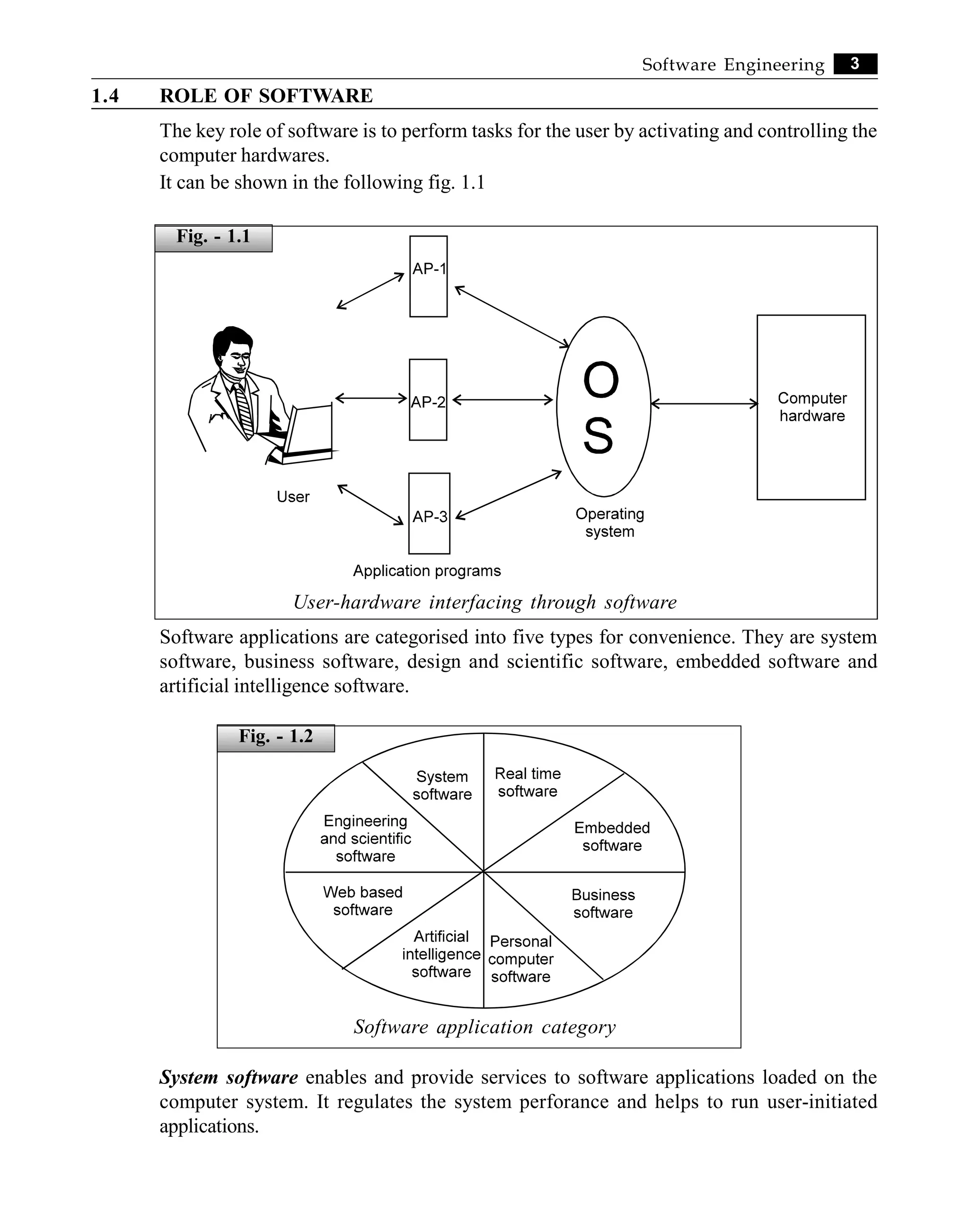
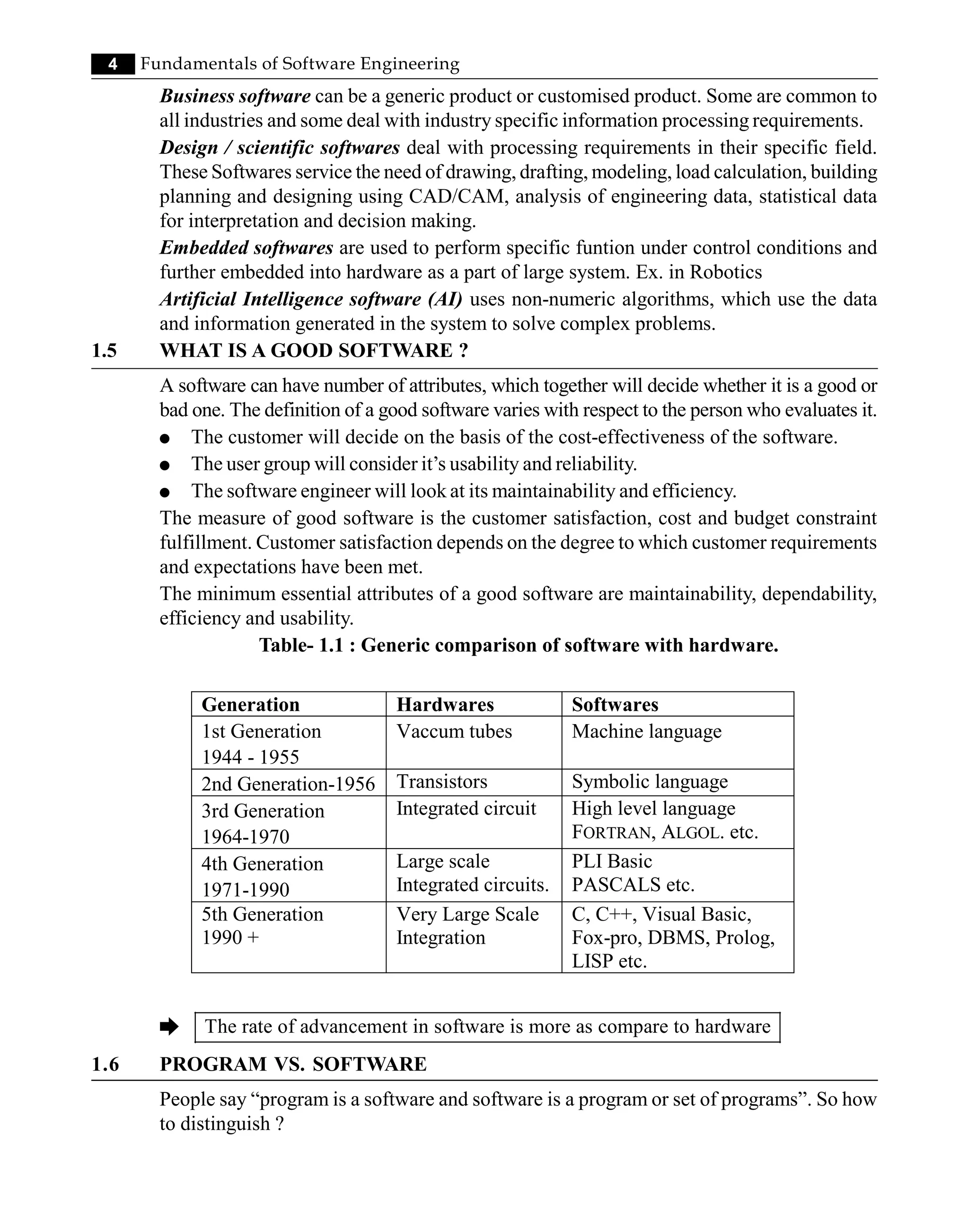
![5
Software Engineering
Program Software
Program vs software
Simple, program comes under the software category or program is a subset of software.A
program can be viewed as
- a set of instructions written for a specific task by individuals.
- small in size and limited functionality.
- it does not hold all the properties of what actually it is intended for.
[size, portability, compatibility, entertaining wide range of inputs, user friendly etc. and lot
more...]
è Program = source code + object code
A software is a broad sense of developing programs that satisfies the criteria like
user friendly
portable
maintainable
fitsto wide range of environments
error / risk free
cost effective etc.
-
-
-
-
-
-
Software consists not only program codes but also of all associated documents (design,
testing operating procedures which includes user manuals and operational manuals.)
è Software = program + documentation + operating procedures
1.7 SOFTWARE CAN BE VIEWED AS A PRODUCT. HOW ?
A product (consumable) which is available in the market is exhausted for the users.
The demand of a product is based on its price, quality, durability. When the demand of the
customers changes w.r.t their taste / use, manufacturers need to modify / redesign these
existing products or to introduce new products time-to-time.
Fig. - 1.3](https://image.slidesharecdn.com/18261342-250527000106-36979acb/75/Fundamentals-Of-Software-Engineering-Engineering-Handbook-1st-Edition-Rajat-Gupta-19-2048.jpg)
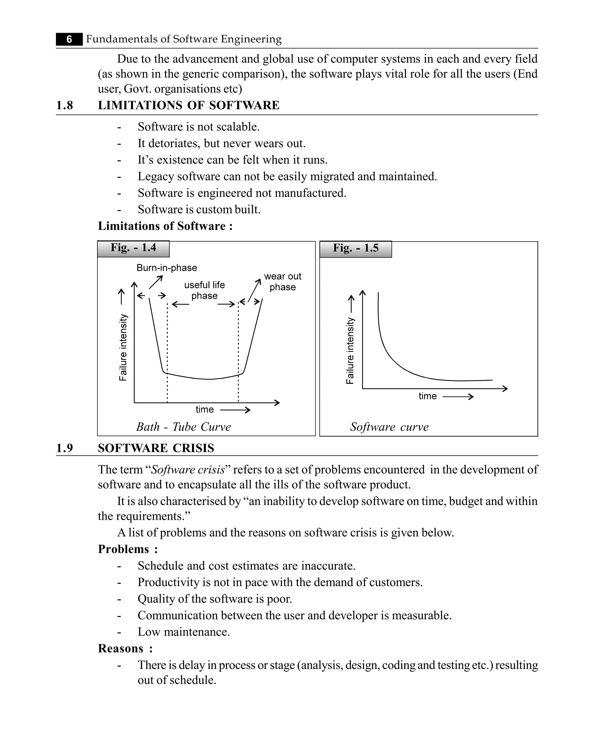
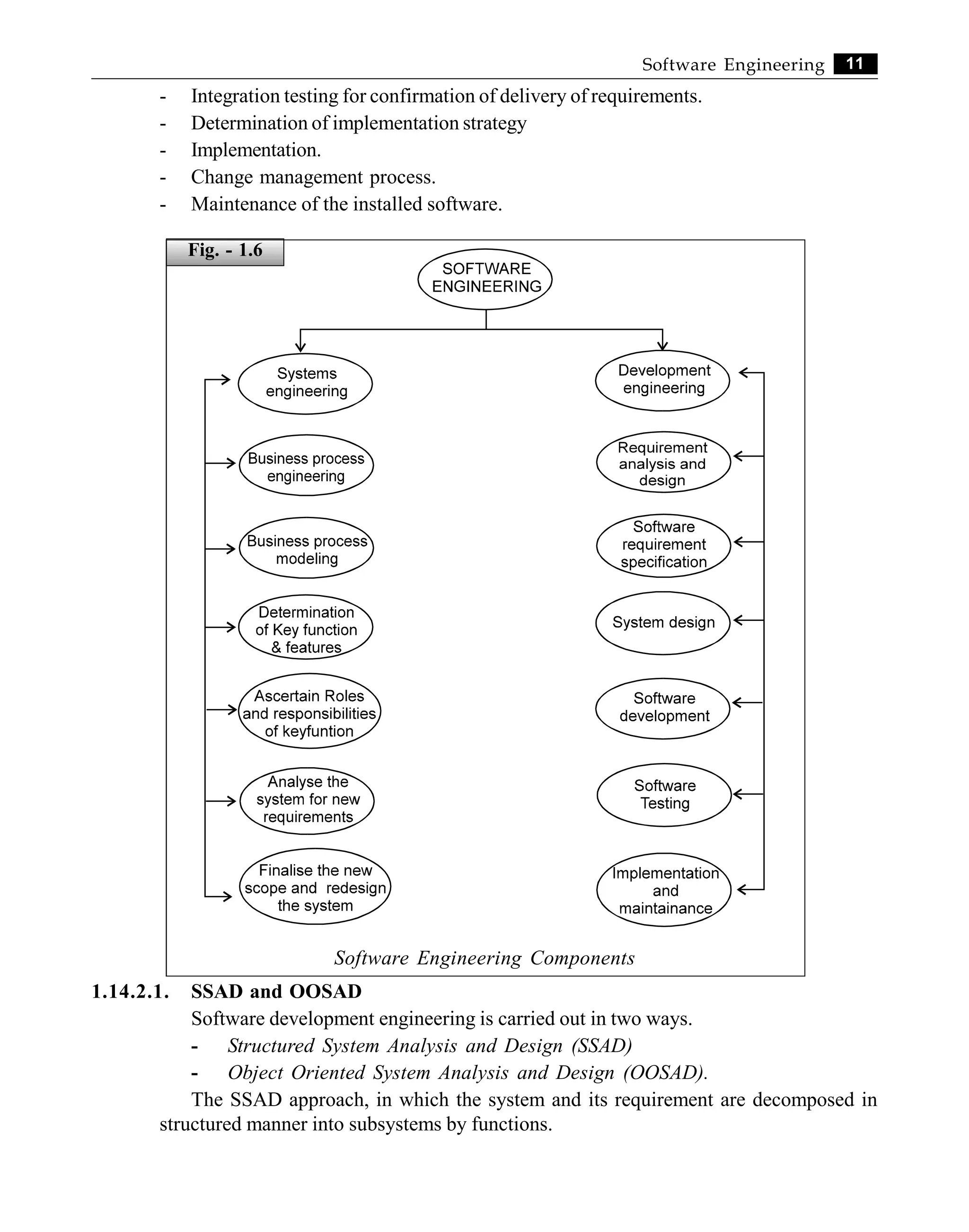
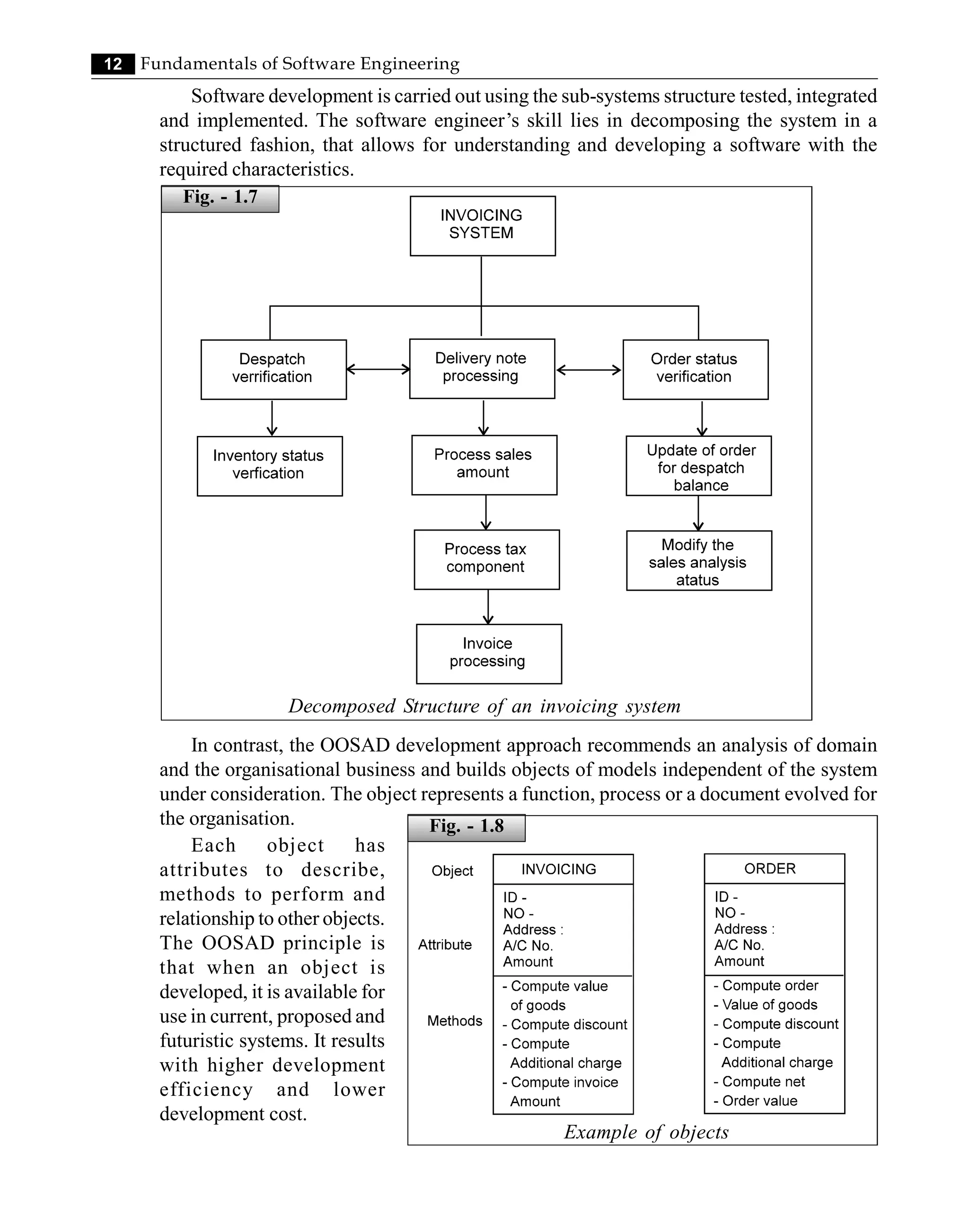
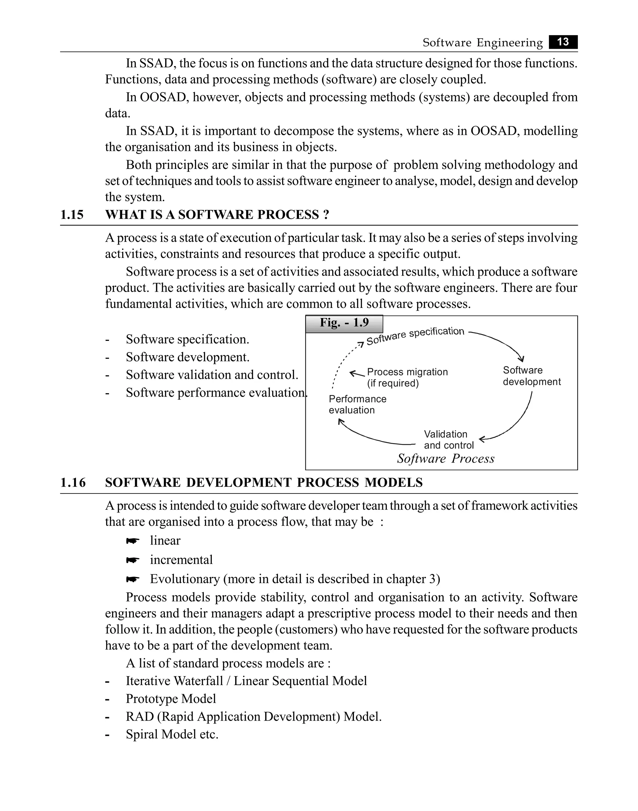
![14 Fundamentals of Software Engineering
1.17 SOFTWARE DEVELOPMENT LIFE CYCLE : (SDLC)
A systematic representation of different phases through which a software product
undergoes from its inception to implementation and modification whenever required.
The highlighted phases / stages of the entire activity for software development are
- User requirements - Feasibility study
- Requirement and Analysis - Design
- Coding - Testing
- Implementation - Maintenance and review
- Modification (whenever required) etc.
[The details are being discussed in chapter - 2.]
1.18 MODERN SOFTWARE DEVELOPMENT
Modern software development is complex for various reasons. It is technology driven
and calls for knowledge on different fronts and management of complex business issues.
Hence, software process management is a key management area in the development of
effective software solutions.
The fig 1.10 shows the key area of management for increasing the effectiveness of process
models.
Modern software process
Software process models will provide the best software solution if these key areas are
managed properly. The organisation and its developers should have good knowledge of
domain, application, tools and technology.
Fig. - 1.10](https://image.slidesharecdn.com/18261342-250527000106-36979acb/75/Fundamentals-Of-Software-Engineering-Engineering-Handbook-1st-Edition-Rajat-Gupta-28-2048.jpg)
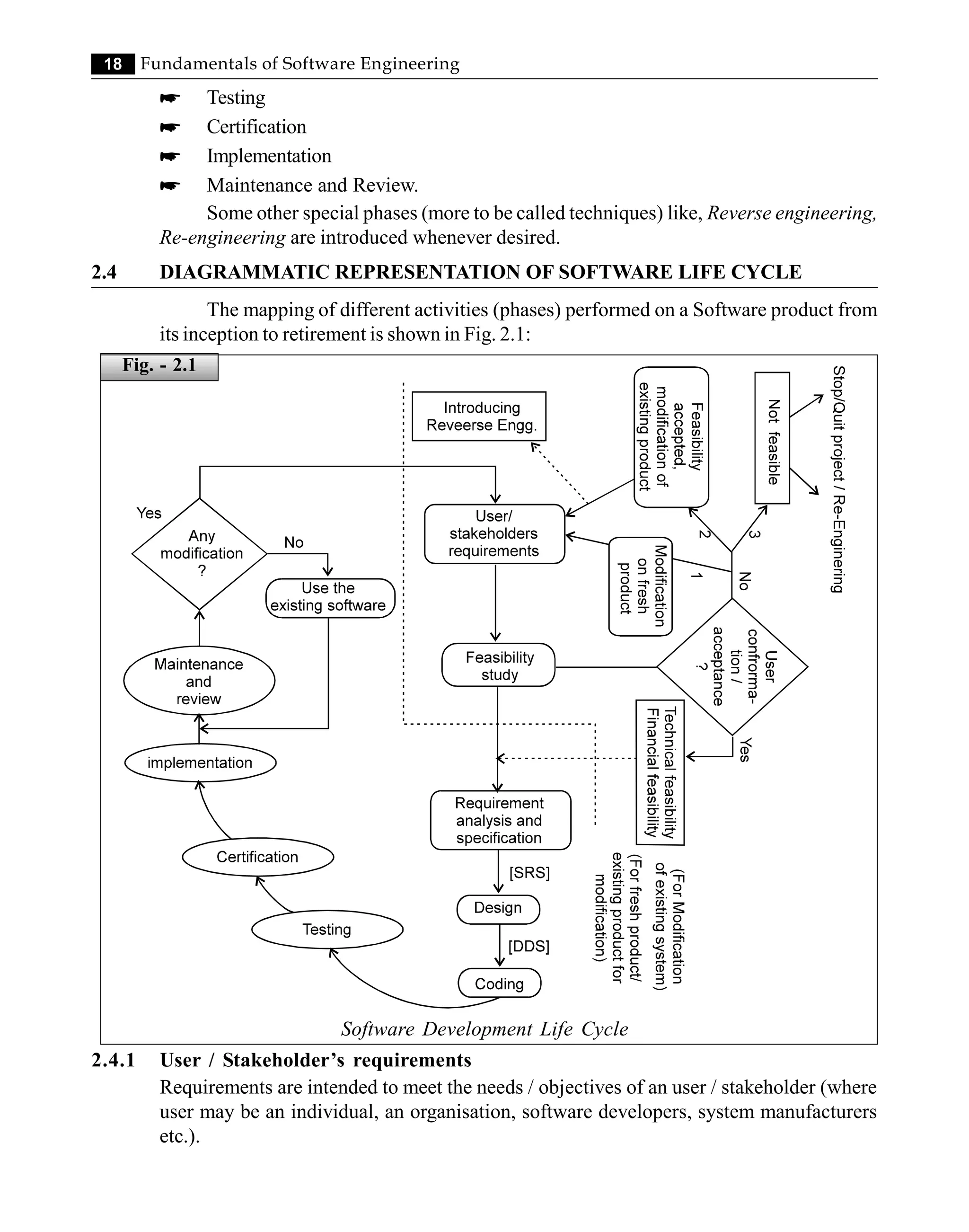
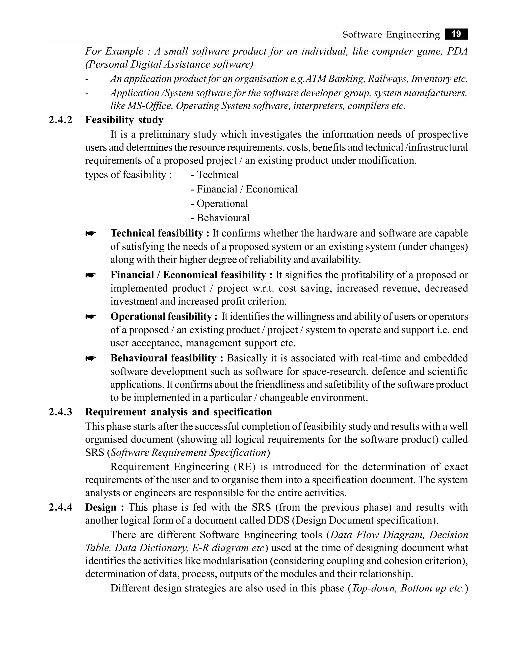
![20 Fundamentals of Software Engineering
2.4.5 Coding : It translates the DDS (from the design phase) into codes under a suitable chosen
language environment. It emphasizes the improvisation of programming efficiency by
reducing the elapsed (execution) time, identification/rectification of errors, and increasing
the throughput (performance) and resource utilisation. It is maintained through LOCs
(Line of codes), FP (Function Point), Feature Point (FP) etc.
2.4.6 Testing : This phase is associated with the activities like quality control measure, detection
of errors on designed modules. During this phase specific test cases are executed and the
actual results from the module under testing are compared with the expected outputs.
The final output of the testing phase is a test report and an error report. It does not
show the absence of defects but the presence of software error.
2.4.7 Certification : The performance of the tested Software product is basically compared
with the standards as framed by some internally recognised organisations like SEI, CMM
and ISO etc.
SEI - Software Engineering Institute
CMM - Capability Maturity Model
ISO - International Organisation for Standardisation. It signifies the overall
reliability of the software product as well as the organisational input in
the user, using the product.
2.4.8 Implementation : It is mainly concerned with ascertaining site selection and preparation,
file conversion and the tasks leading immediately to a fully operational system.
It also includes the final testing of the complete software product to the user
satisfaction, producing security to the system.
2.4.9 Maintenance and review : It is an important phase of SDLC, it includes the correction of
errors and the changes needed on the Software product.
It may be classified as -
i) Corrective
ii) Adaptive
iii) Perfective
iv) Preventive maintenance
Review is a set of activities which is conducted by the software analyst / system analyst
on the basis of following attributes.
- Case of use
- Level of Utilisation
- Response time
- Suitability of information
- Overall reliability
2.4.10 Special phases : [Techniques]
To have an overview on this type of phases, Let’s consider the dotted portion of the
SDLC as given in Fig. 2.1 :](https://image.slidesharecdn.com/18261342-250527000106-36979acb/75/Fundamentals-Of-Software-Engineering-Engineering-Handbook-1st-Edition-Rajat-Gupta-34-2048.jpg)
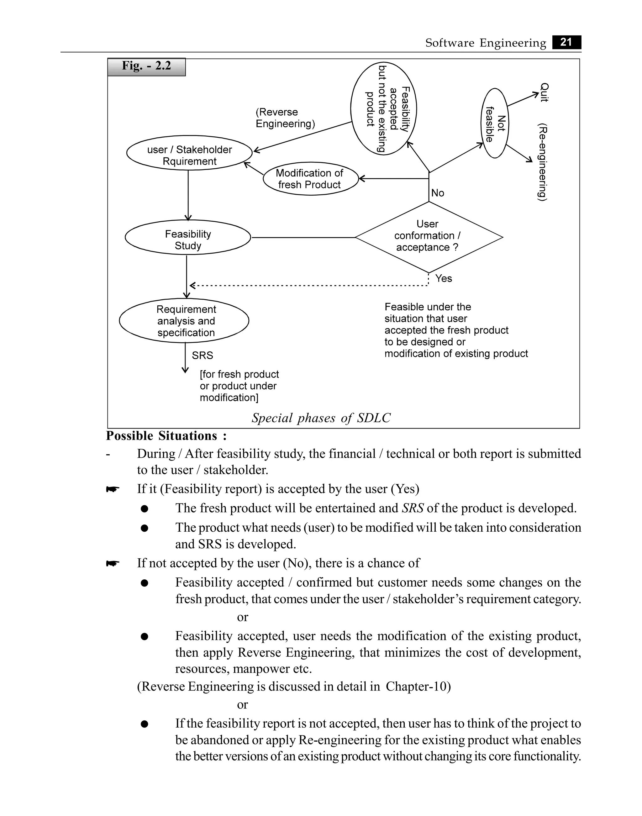
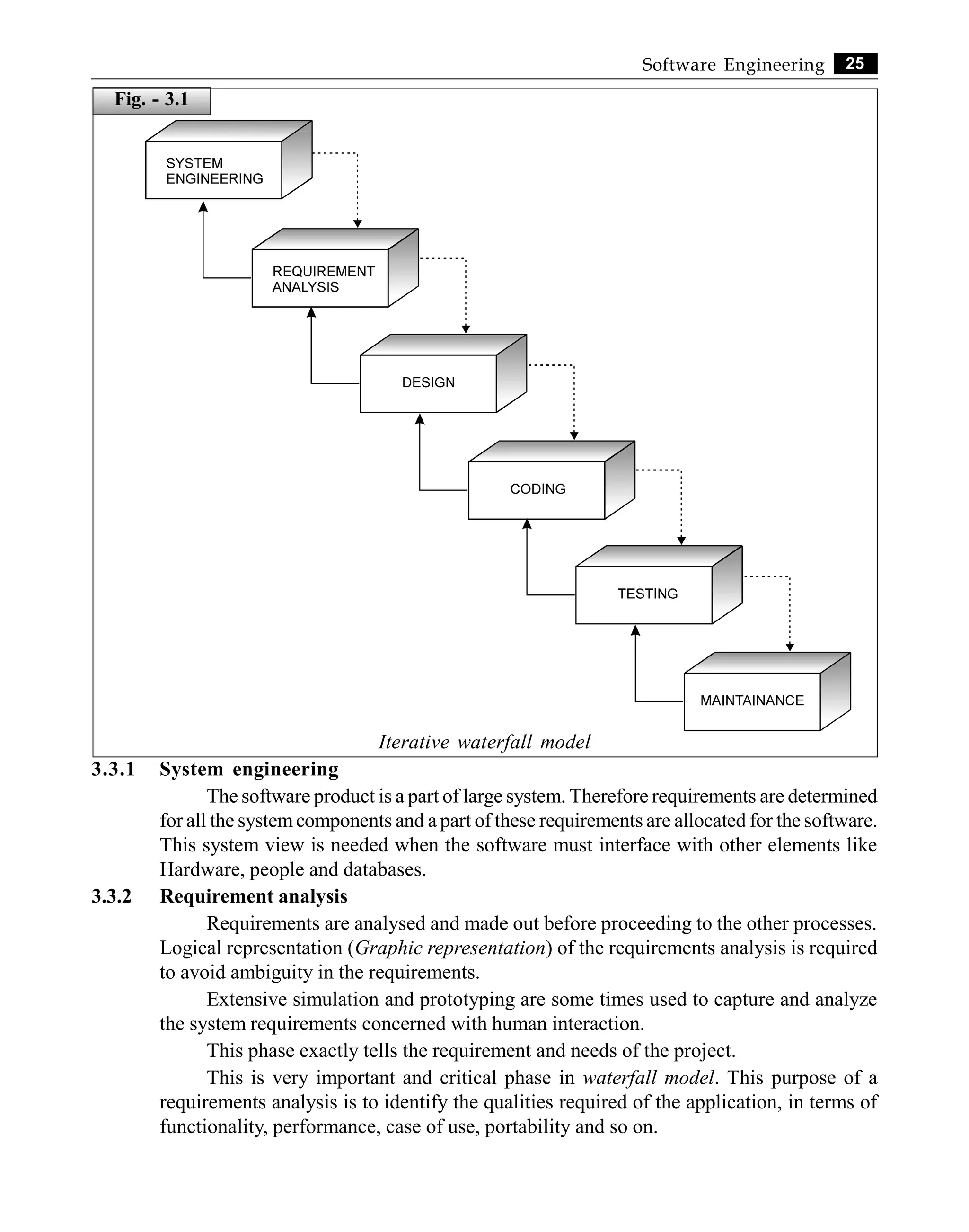
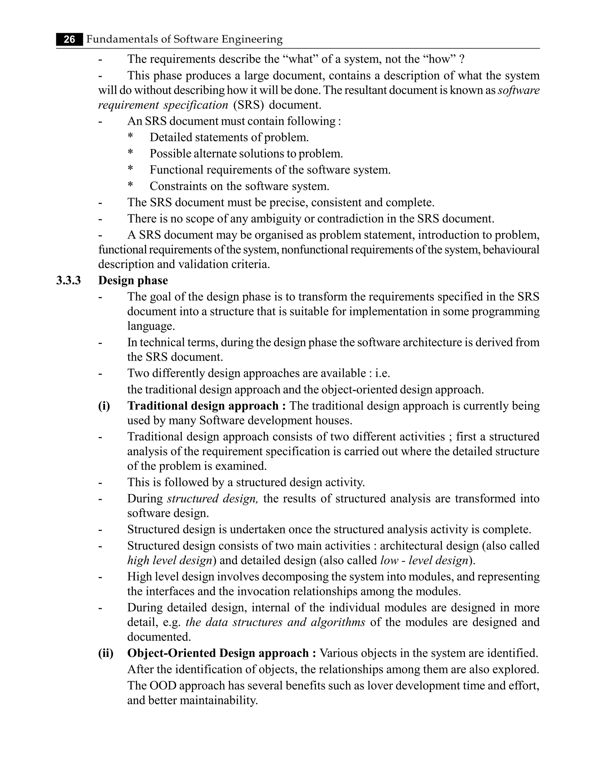
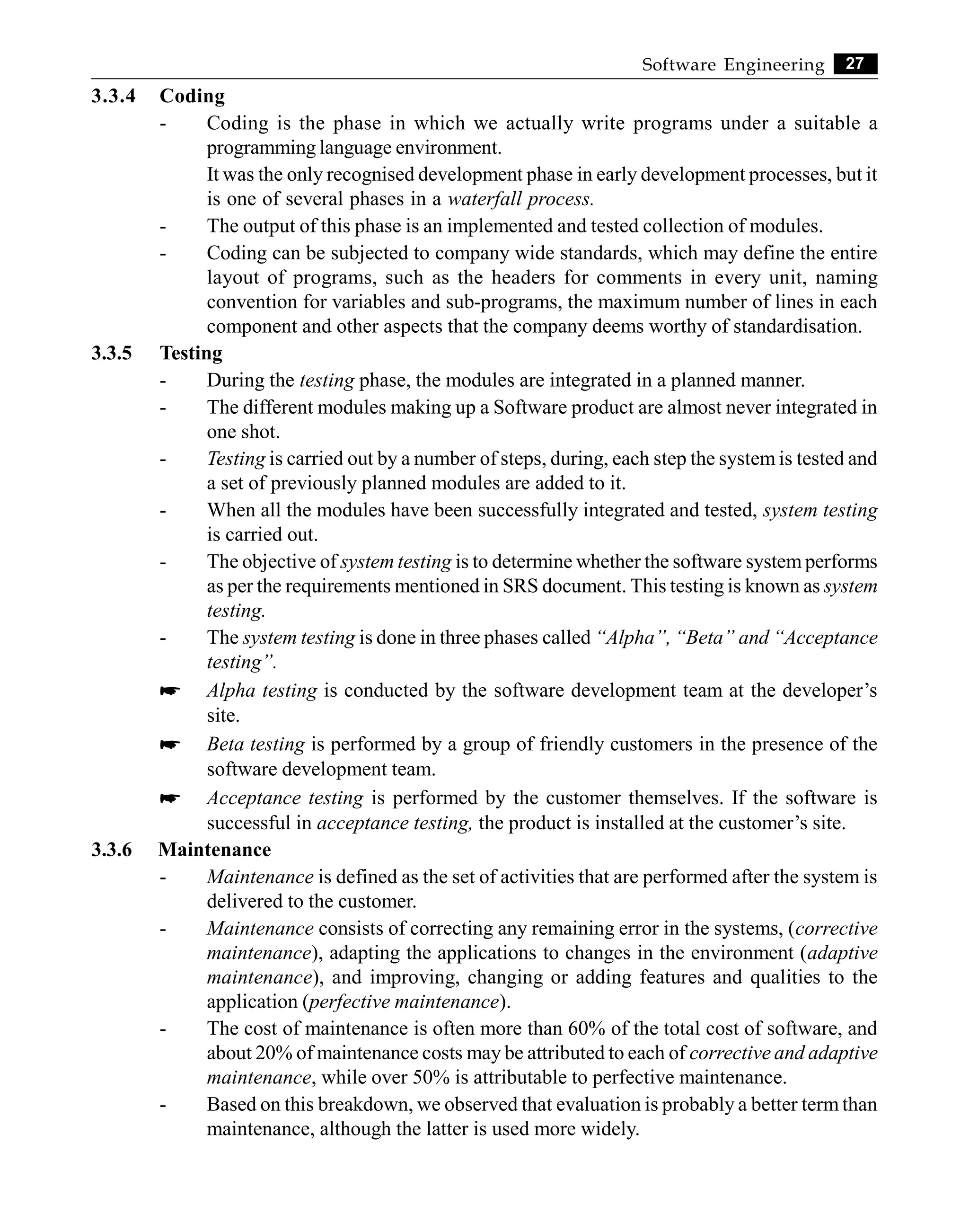
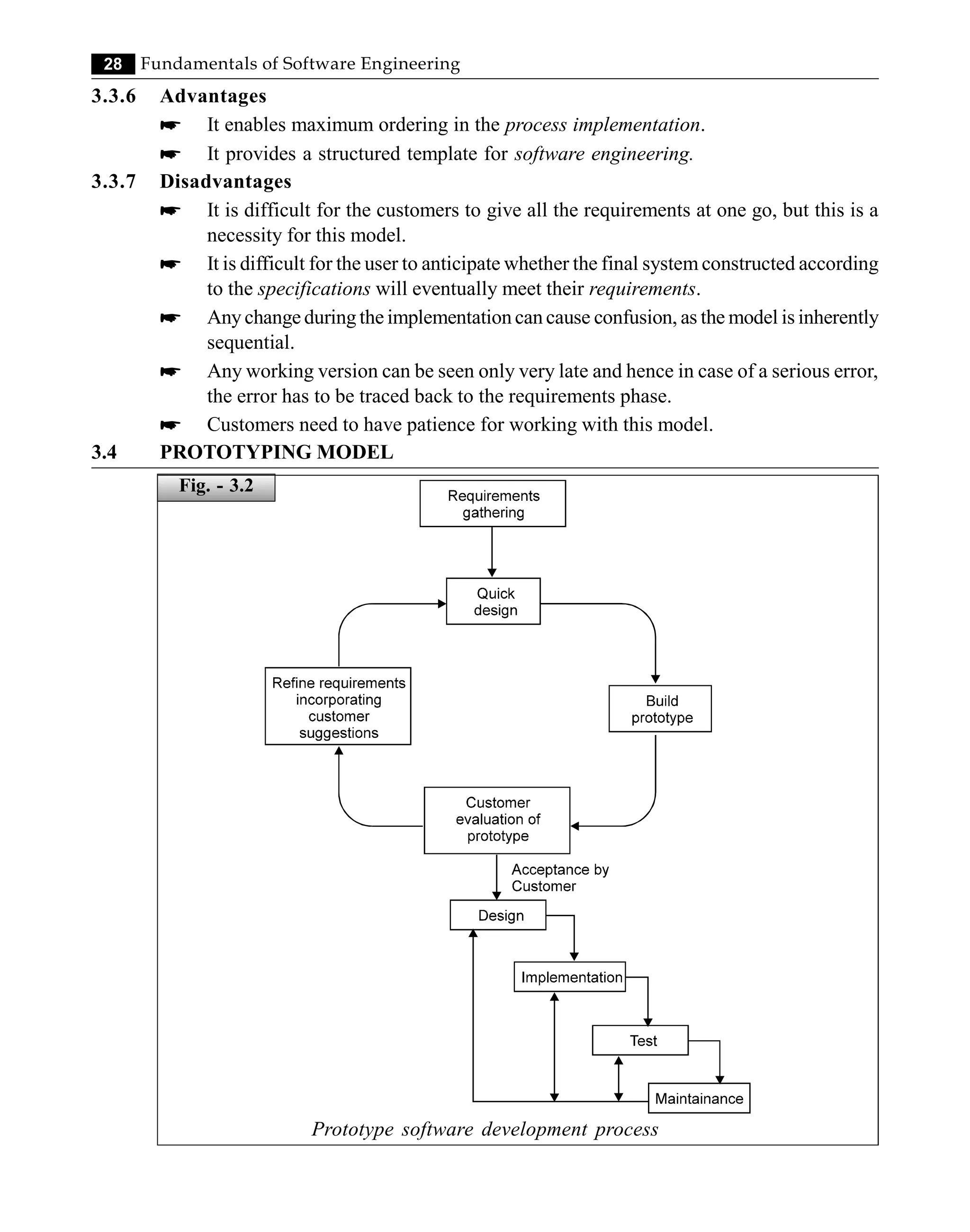
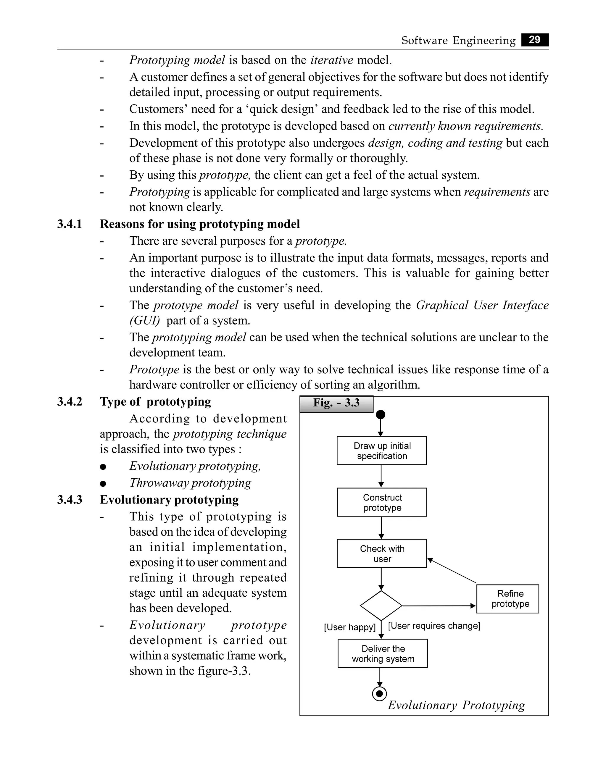
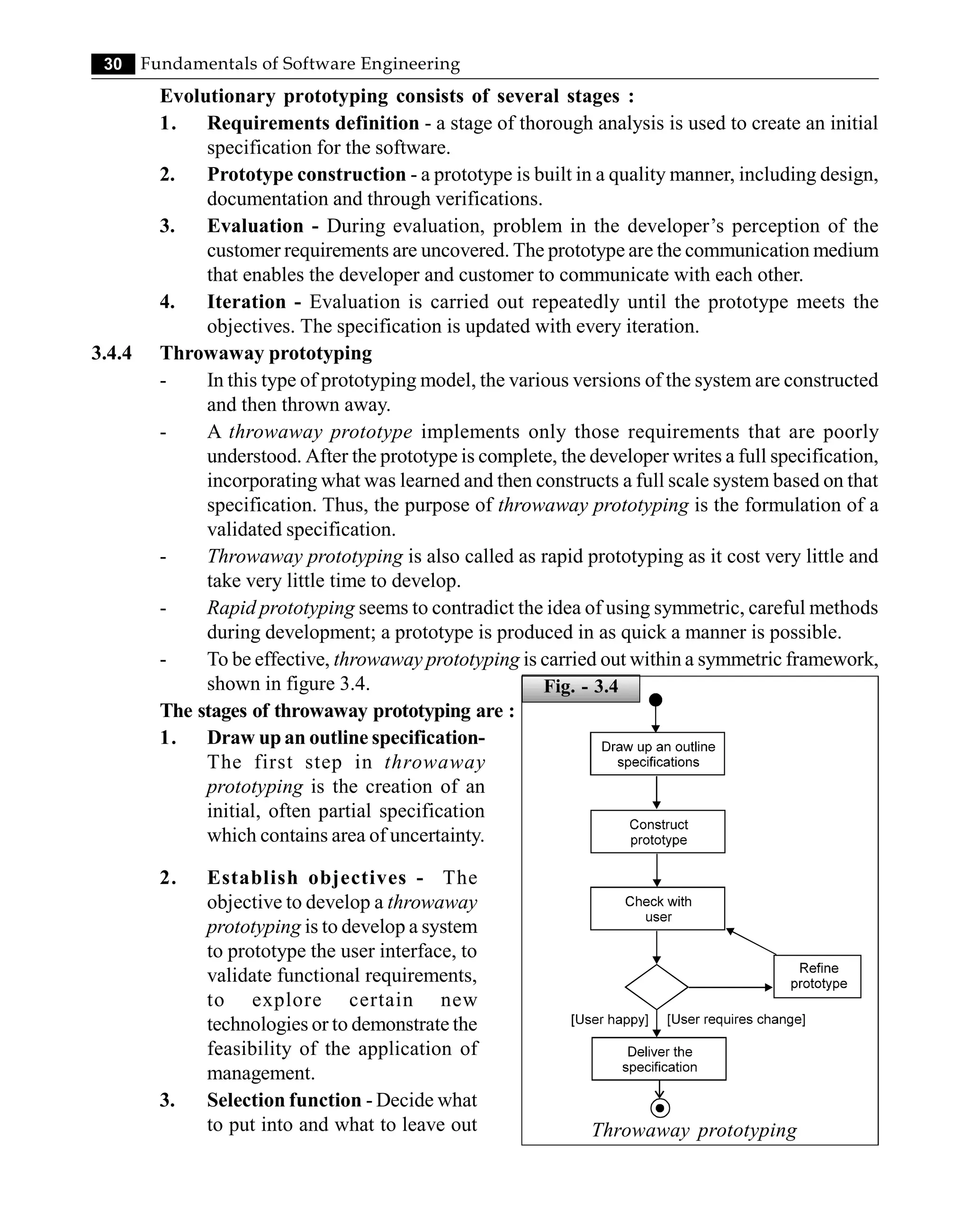
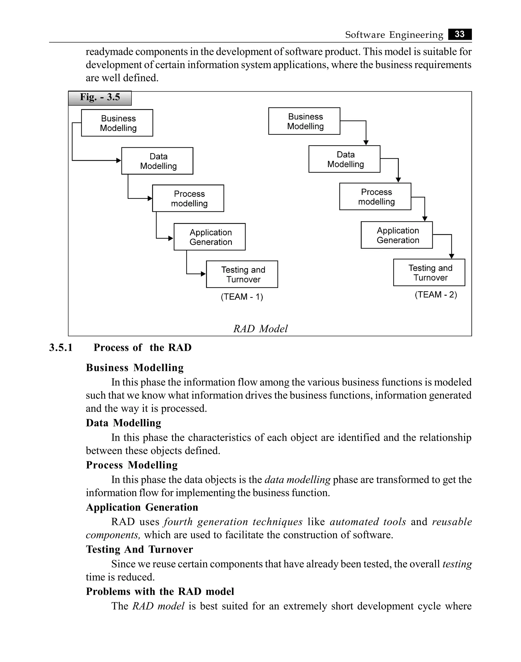
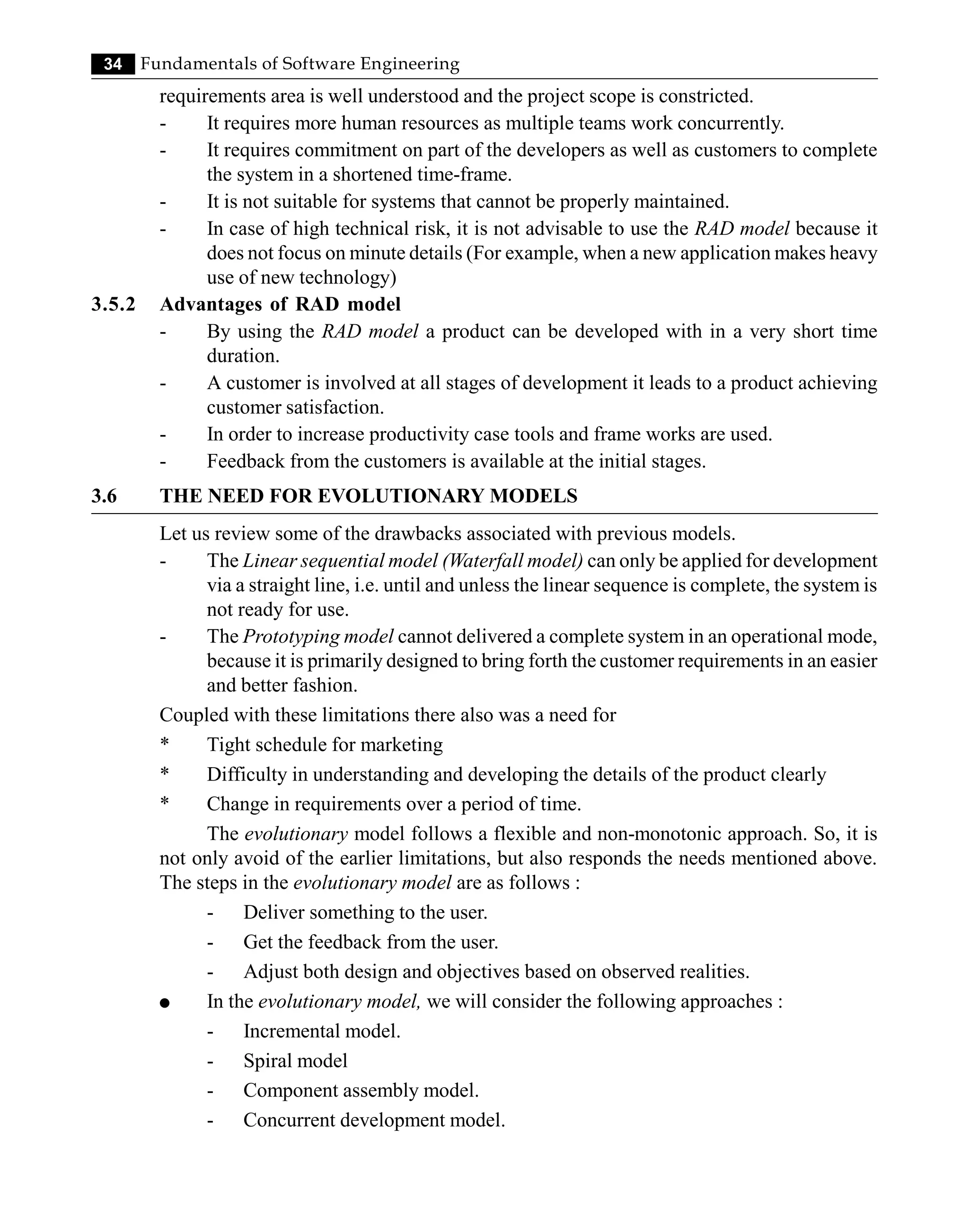
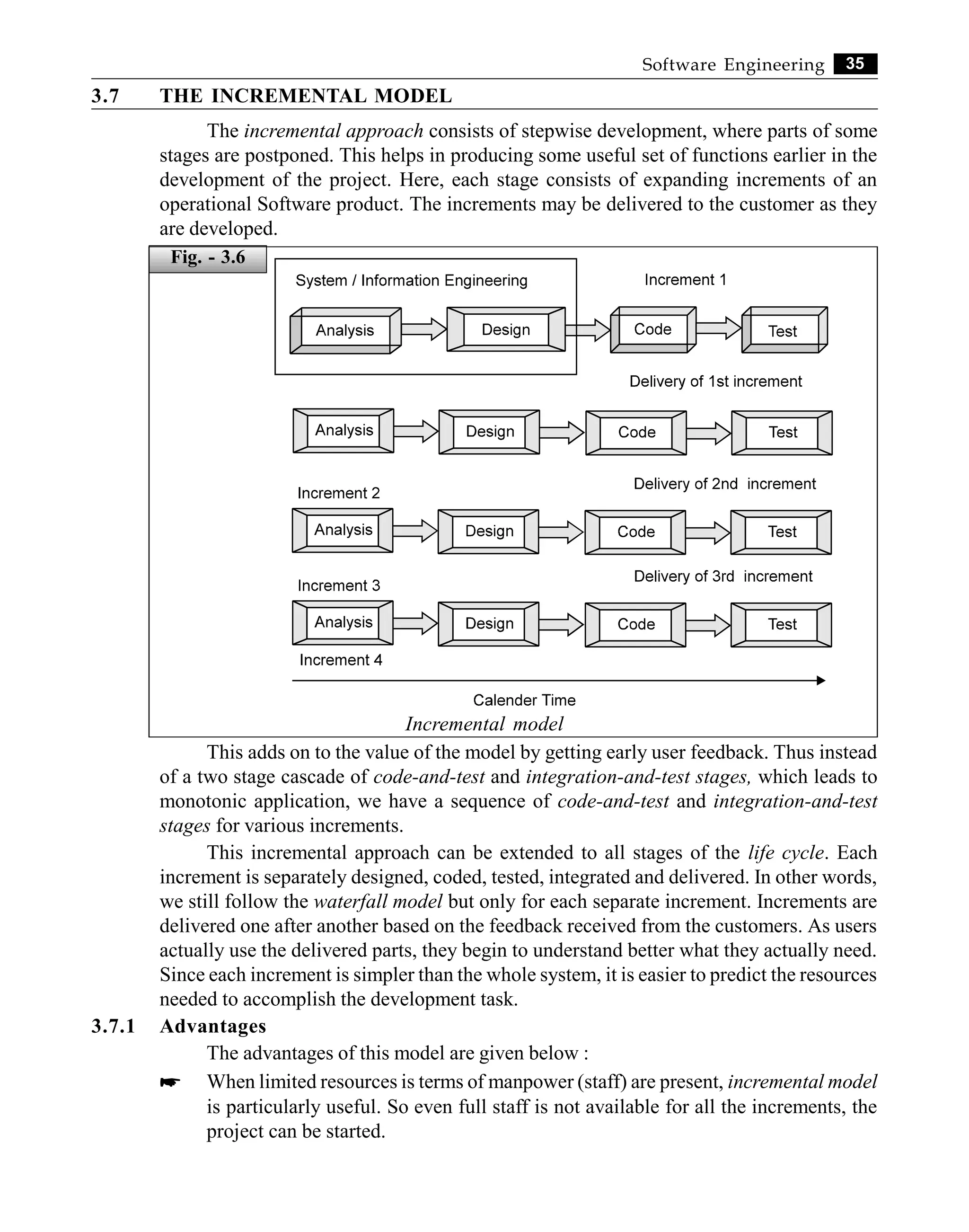
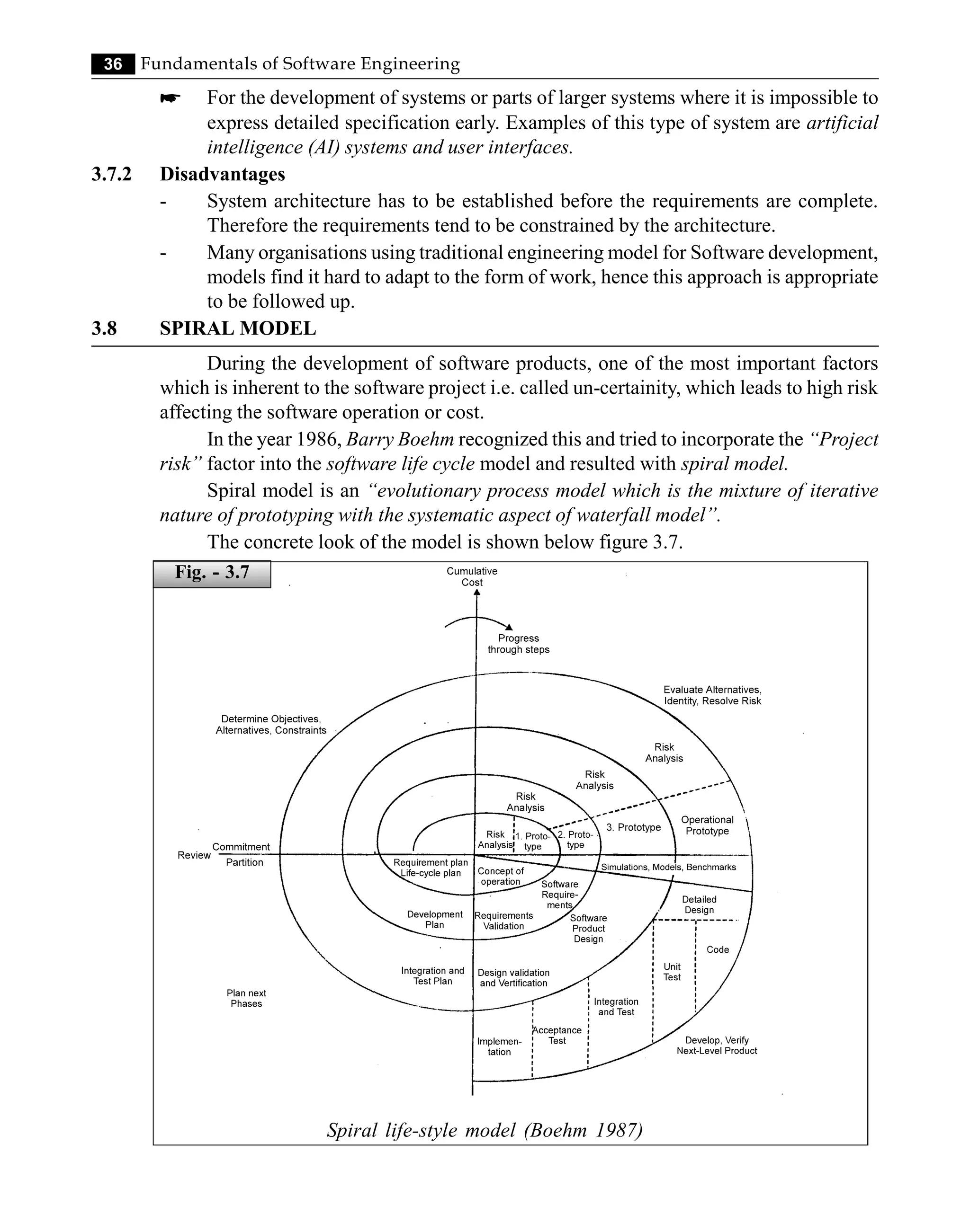
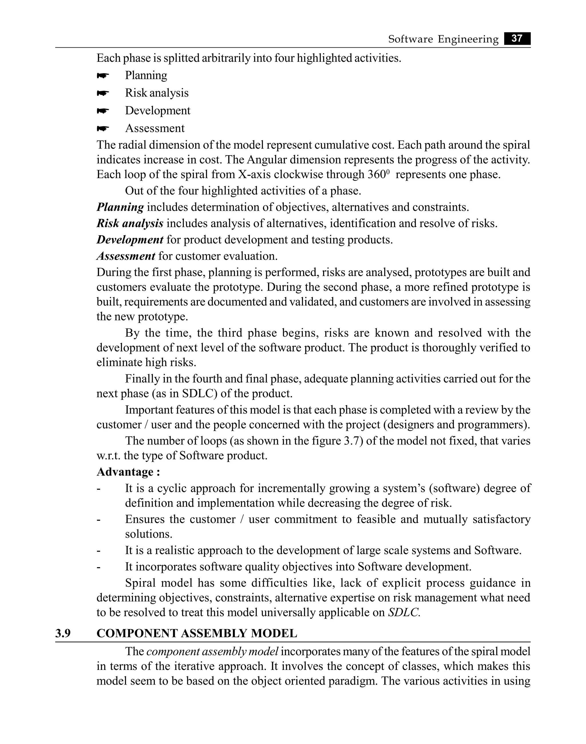
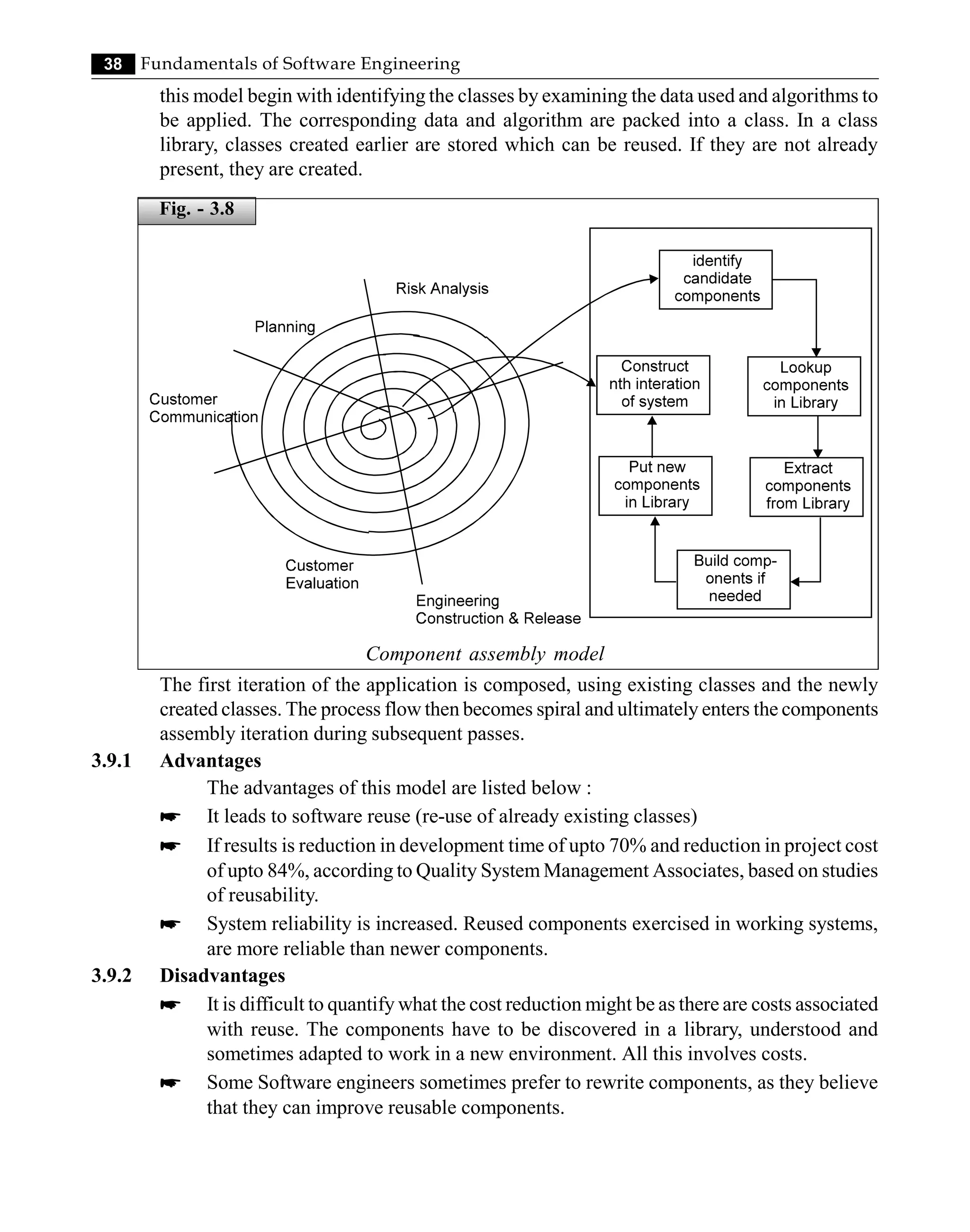
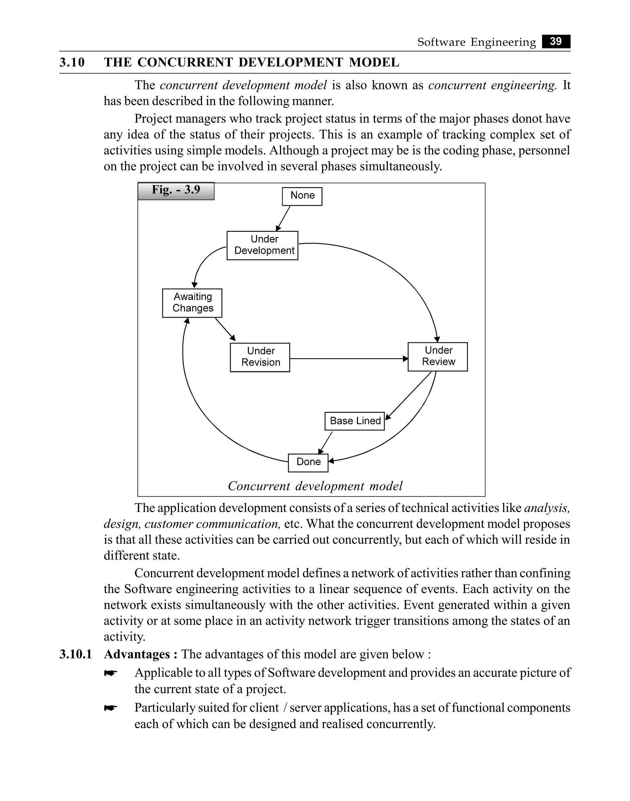


![This ebook is for the use of anyone anywhere in the United States and most other
parts of the world at no cost and with almost no restrictions whatsoever. You may
copy it, give it away or re-use it under the terms of the Project Gutenberg License
included with this ebook or online at www.gutenberg.org. If you are not located in
the United States, you will have to check the laws of the country where you are
located before using this eBook.
Title: The Anatomy of Bridgework
Author: William Henry Thorpe
Release date: December 6, 2013 [eBook #44371]
Most recently updated: October 23, 2024
Language: English
Credits: Produced by Chris Curnow, Harry Lamé and the Online
Distributed Proofreading Team at http://www.pgdp.net (This
file was produced from images generously made available
by The Internet Archive)
*** START OF THE PROJECT GUTENBERG EBOOK THE ANATOMY OF BRIDGEWORK
***](https://image.slidesharecdn.com/18261342-250527000106-36979acb/75/Fundamentals-Of-Software-Engineering-Engineering-Handbook-1st-Edition-Rajat-Gupta-60-2048.jpg)