Airport
Airport
Engineering
Engineering
Unit-4
Unit-4
Prof. P. V.Khandve
Prof. P. V. Khandve
B.E.Civil, M.Tech.(Env.Engg.)(Hons.),
B.E.Civil, M.Tech.(Env.Engg.)(Hons.),
D.B.M., D.I.D., D.I.T., D.I.J., B.A.Soc.
D.B.M., D.I.D., D.I.T., D.I.J., B.A.Soc.
M.I.E., M.I.S.T.E., M.I.S.E.T, M.I.S.C.A., M.I.W.W.A., M.I.A.S.
2.
Airport Engg byPVK
2
Surveys for site selection
Surveys for site selection
Traffic surveys – traffic volume, traffic intensity etc
Traffic surveys – traffic volume, traffic intensity etc
Meteorological survey - direction, duration,
Meteorological survey - direction, duration,
intensity of wind, rainfall, fog, temperature &
intensity of wind, rainfall, fog, temperature &
pressure
pressure
Topographical Survey – topography of ground,
Topographical Survey – topography of ground,
trees, streams, contour map, Location map,
trees, streams, contour map, Location map,
Layout map, etc.
Layout map, etc.
Soil survey – type of soil, properties of soil, ground
Soil survey – type of soil, properties of soil, ground
water table details etc.
water table details etc.
Drainage survey – quantity of storm water,
Drainage survey – quantity of storm water,
pattern of drainage, possibilities of diversions etc.
pattern of drainage, possibilities of diversions etc.
Material survey – availability of construction
Material survey – availability of construction
material etc
material etc
TMTSDM
TMTSDM
3.
Airport Engg byPVK
3
Airport Site Selection
Airport Site Selection
Regional Plan – National network of airport
Regional Plan – National network of airport
Airport use – Civil or military use
Airport use – Civil or military use
Proximity to other airports – Small – 2 miles, big – 4
Proximity to other airports – Small – 2 miles, big – 4
miles, piston engine – 16 miles, jet engine – 100 miles
miles, piston engine – 16 miles, jet engine – 100 miles
Ground accessibility – 30 m distance, near highway,
Ground accessibility – 30 m distance, near highway,
bus stand and railway station.
bus stand and railway station.
Topography – raised ground, hill top, less obstruction,
Topography – raised ground, hill top, less obstruction,
natural drainage, uniform wind, better visibility (fog)
natural drainage, uniform wind, better visibility (fog)
Obstructions – landing or takeoff – approach areas,
Obstructions – landing or takeoff – approach areas,
less fences, trees, poles, lines, buildings etc. future
less fences, trees, poles, lines, buildings etc. future
growth, controlled by zoning laws
growth, controlled by zoning laws
Visibility – free from visibility reduction conditions, fog,
Visibility – free from visibility reduction conditions, fog,
smoke, smog etc., industrial area proximity checked
smoke, smog etc., industrial area proximity checked
4.
Airport Engg byPVK
4
Airport Site Selection
Airport Site Selection
Wind – Orientation of runway, windword side of city
Wind – Orientation of runway, windword side of city
Noise nuisance – engine noise, buffer zone,
Noise nuisance – engine noise, buffer zone,
preferential runway used.
preferential runway used.
Grading, Drainage and Soil characteristics –
Grading, Drainage and Soil characteristics –
construction and maintenance, grading, and
construction and maintenance, grading, and
drainage system, gravel, sand mix
drainage system, gravel, sand mix
Future Development – provisions for expansion,
Future Development – provisions for expansion,
parking, passanger facilities
parking, passanger facilities
Availability of utilities from towns – water supply,
Availability of utilities from towns – water supply,
electricity, sewer, telephone etc.
electricity, sewer, telephone etc.
Economic consideration – land cost, clearing,
Economic consideration – land cost, clearing,
grading, drainage, construction, roads, parking,
grading, drainage, construction, roads, parking,
facilities etc. cost
facilities etc. cost
5.
Airport Engg byPVK
5
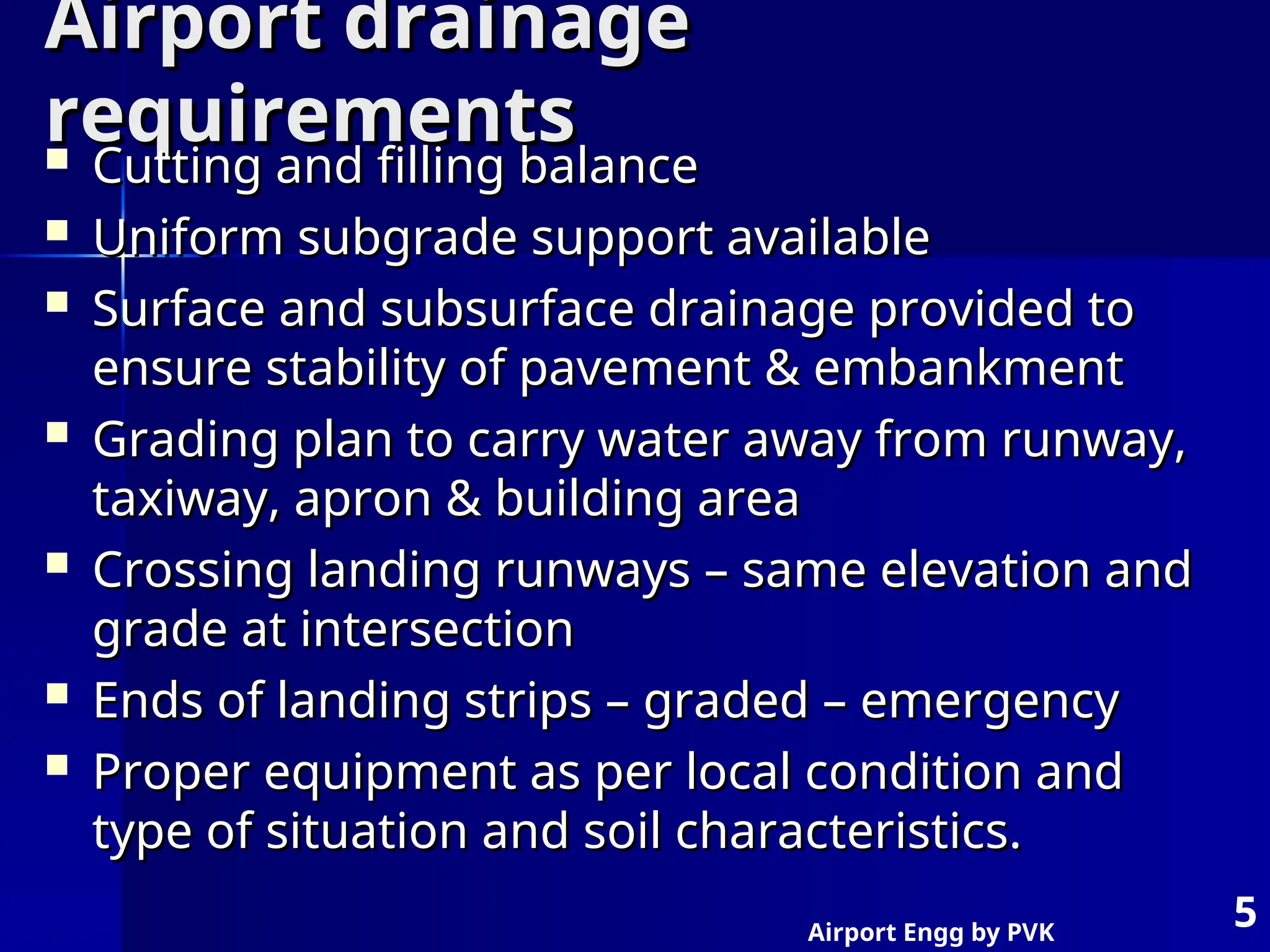
Airport drainage
Airport drainage
requirements
requirements
Cutting and filling balance
Cutting and filling balance
Uniform subgrade support available
Uniform subgrade support available
Surface and subsurface drainage provided to
Surface and subsurface drainage provided to
ensure stability of pavement & embankment
ensure stability of pavement & embankment
Grading plan to carry water away from runway,
Grading plan to carry water away from runway,
taxiway, apron & building area
taxiway, apron & building area
Crossing landing runways – same elevation and
Crossing landing runways – same elevation and
grade at intersection
grade at intersection
Ends of landing strips – graded – emergency
Ends of landing strips – graded – emergency
Proper equipment as per local condition and
Proper equipment as per local condition and
type of situation and soil characteristics.
type of situation and soil characteristics.
6.
Airport Engg byPVK
6
Functions of Airport Drainage system
Functions of Airport Drainage system
Removal of surface run off the airfield
Removal of surface run off the airfield
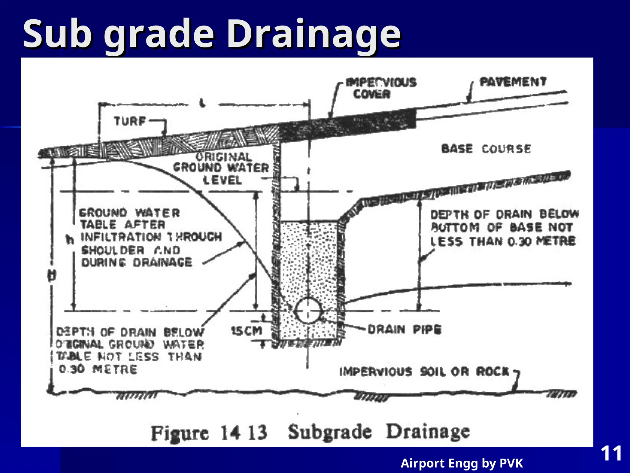
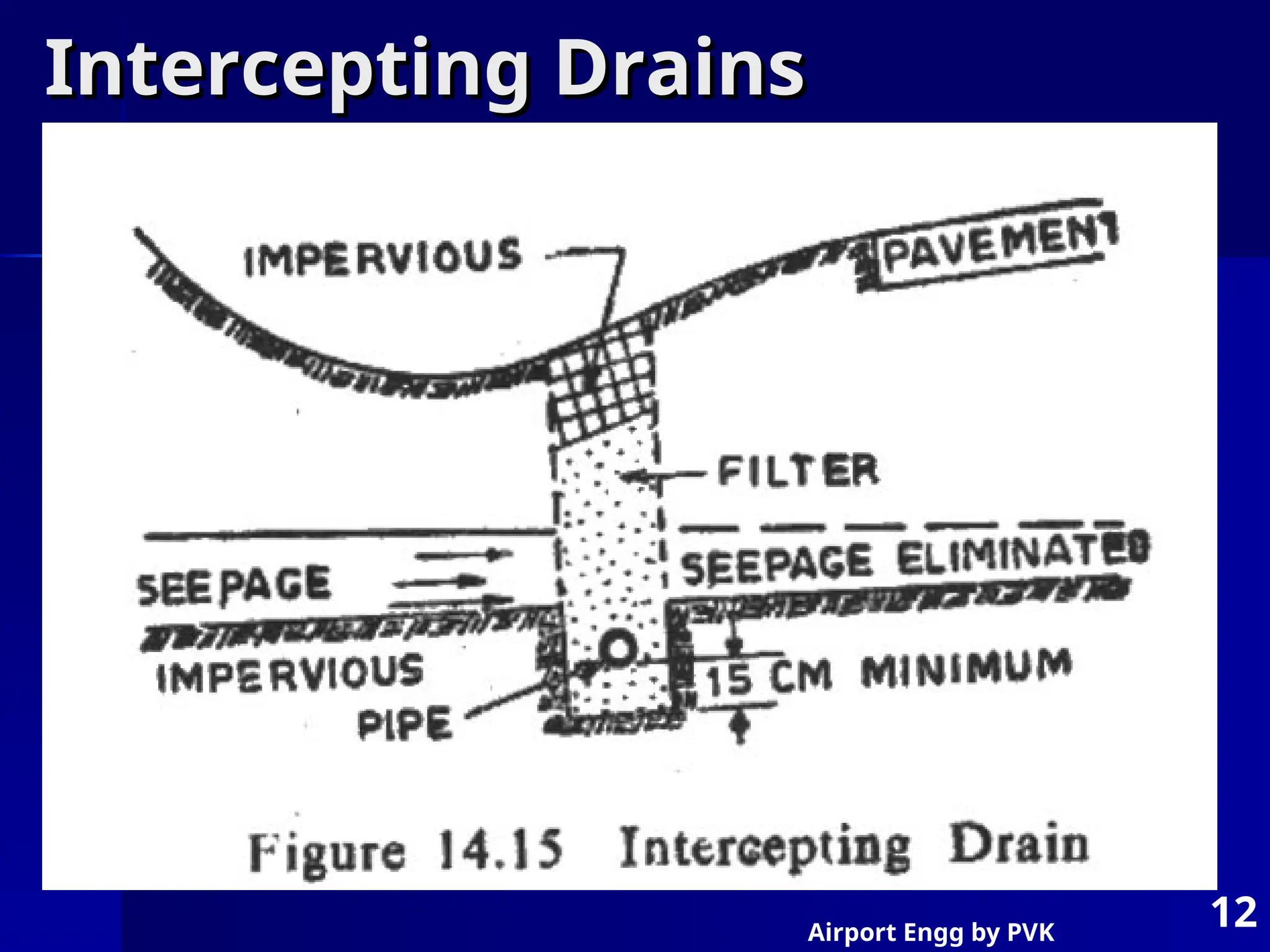
Interception of surface and ground water
Interception of surface and ground water
flow originating from land adjacent to airfield
flow originating from land adjacent to airfield
Diversion of surface and ground water flow
Diversion of surface and ground water flow
originating from land adjacent to airfield
originating from land adjacent to airfield
Lowering of subsurface water level in the
Lowering of subsurface water level in the
airfield areas.
airfield areas.
Providing safety of aircraft
Providing safety of aircraft
Providing long life of runway pavement
Providing long life of runway pavement
7.
Airport Engg byPVK
7
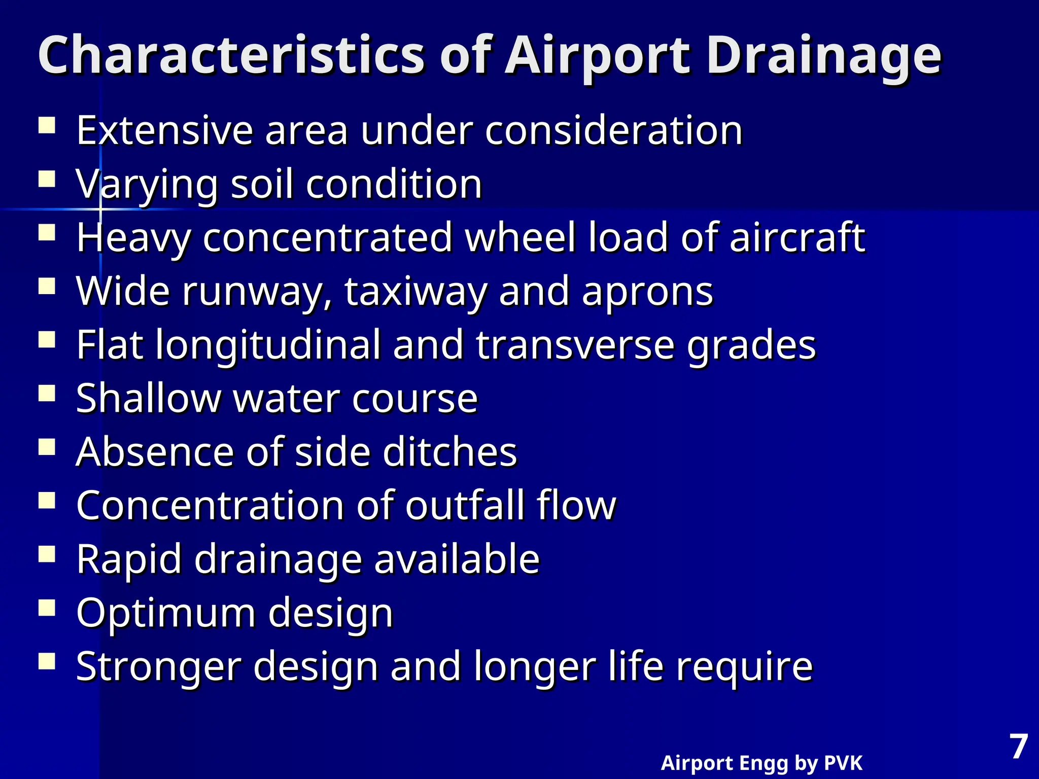
Characteristics of Airport Drainage
Characteristics of Airport Drainage
Extensive area under consideration
Extensive area under consideration
Varying soil condition
Varying soil condition
Heavy concentrated wheel load of aircraft
Heavy concentrated wheel load of aircraft
Wide runway, taxiway and aprons
Wide runway, taxiway and aprons
Flat longitudinal and transverse grades
Flat longitudinal and transverse grades
Shallow water course
Shallow water course
Absence of side ditches
Absence of side ditches
Concentration of outfall flow
Concentration of outfall flow
Rapid drainage available
Rapid drainage available
Optimum design
Optimum design
Stronger design and longer life require
Stronger design and longer life require
8.
Airport Engg byPVK
8
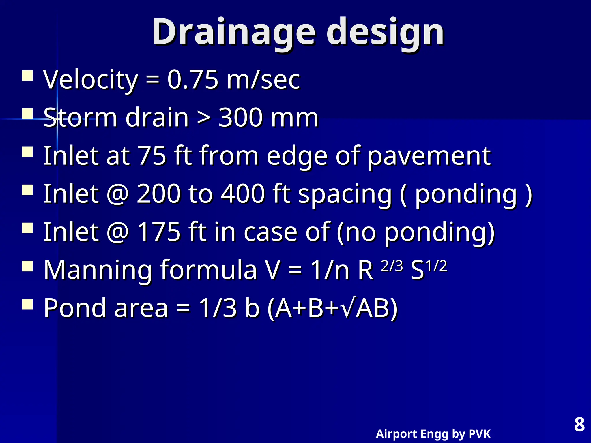
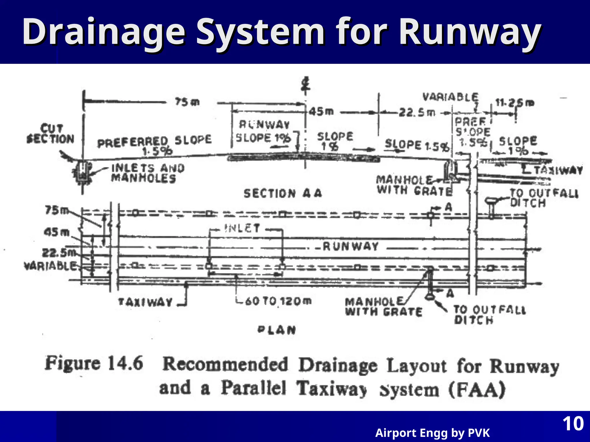
Drainage design
Drainage design
Velocity = 0.75 m/sec
Velocity = 0.75 m/sec
Storm drain > 300 mm
Storm drain > 300 mm
Inlet at 75 ft from edge of pavement
Inlet at 75 ft from edge of pavement
Inlet @ 200 to 400 ft spacing ( ponding )
Inlet @ 200 to 400 ft spacing ( ponding )
Inlet @ 175 ft in case of (no ponding)
Inlet @ 175 ft in case of (no ponding)
Manning formula V = 1/n R
Manning formula V = 1/n R 2/3
2/3
S
S1/2
1/2
Pond area = 1/3 b (A+B+ AB)
√
Pond area = 1/3 b (A+B+ AB)
√
9.
Airport Engg byPVK
9
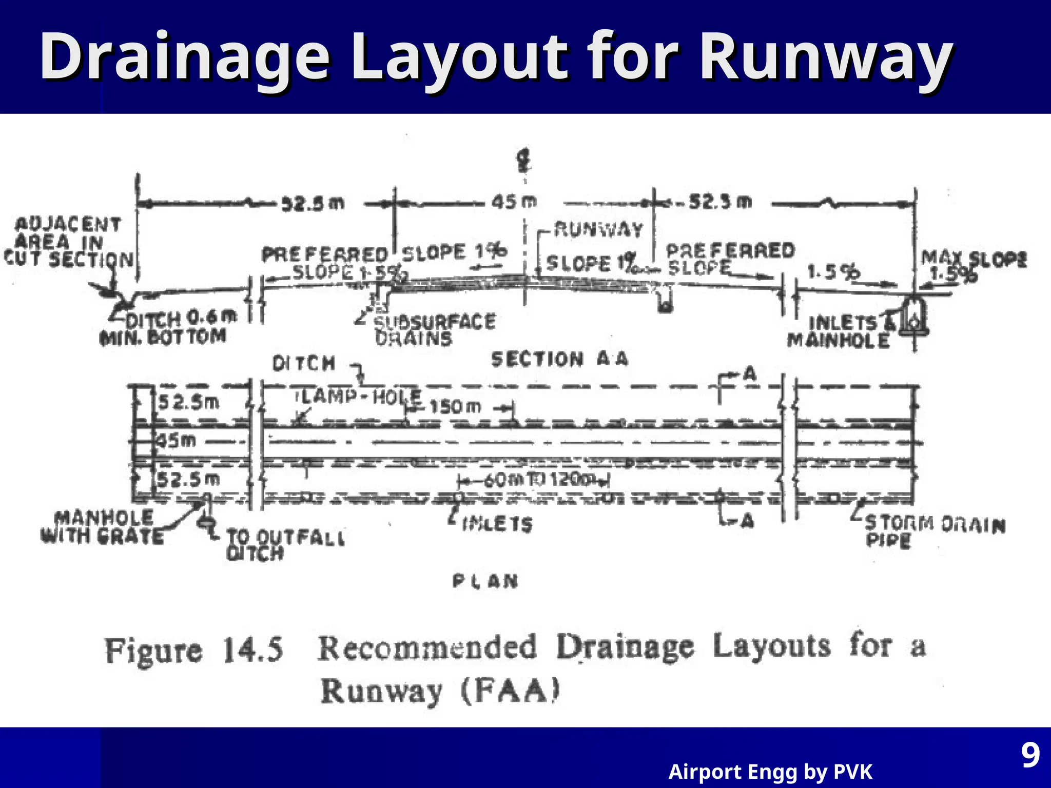
Drainage Layout for Runway
Drainage Layout for Runway
10.
Airport Engg byPVK
10
Drainage System for Runway
Drainage System for Runway
Airport Engg byPVK
13
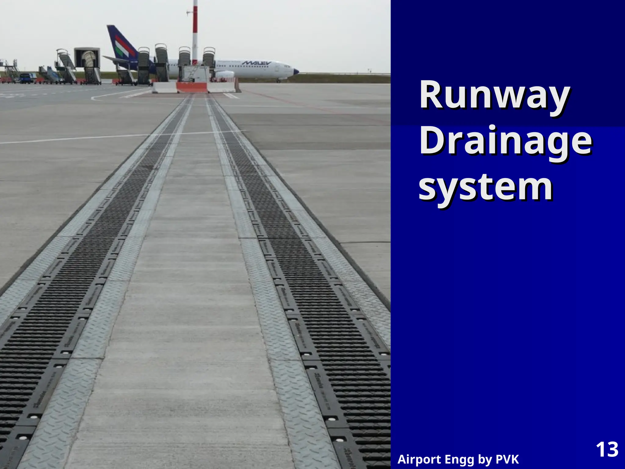
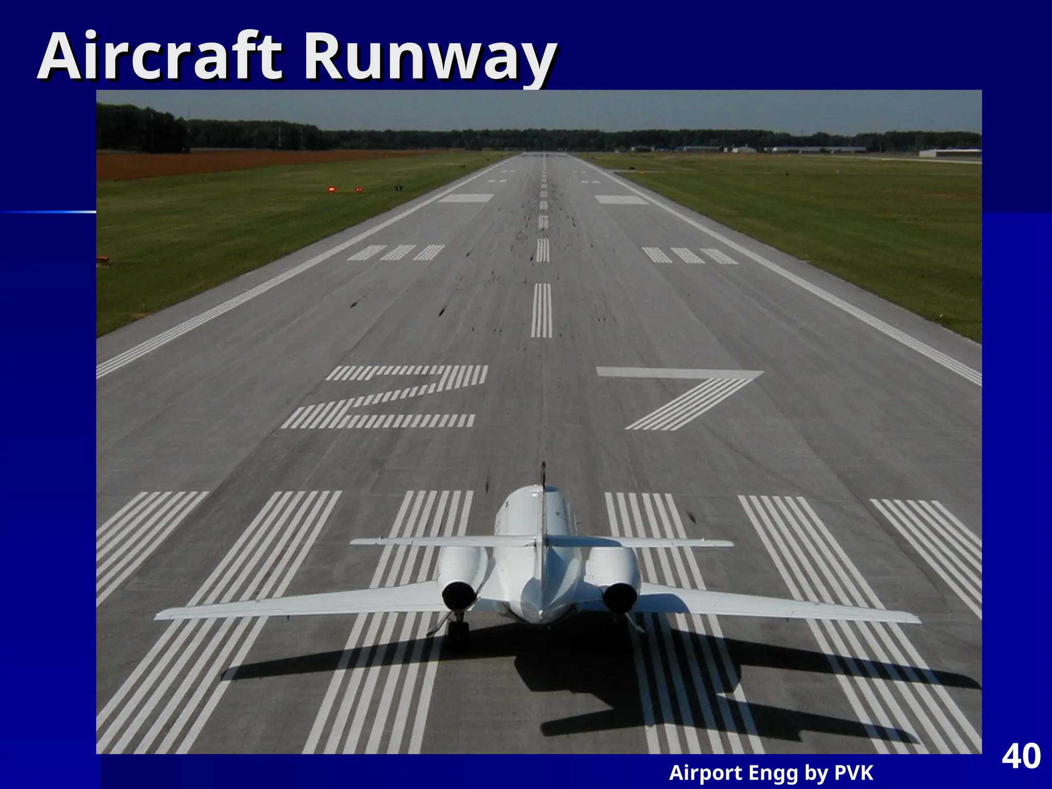
Runway
Runway
Drainage
Drainage
system
system
14.
Airport Engg byPVK
14
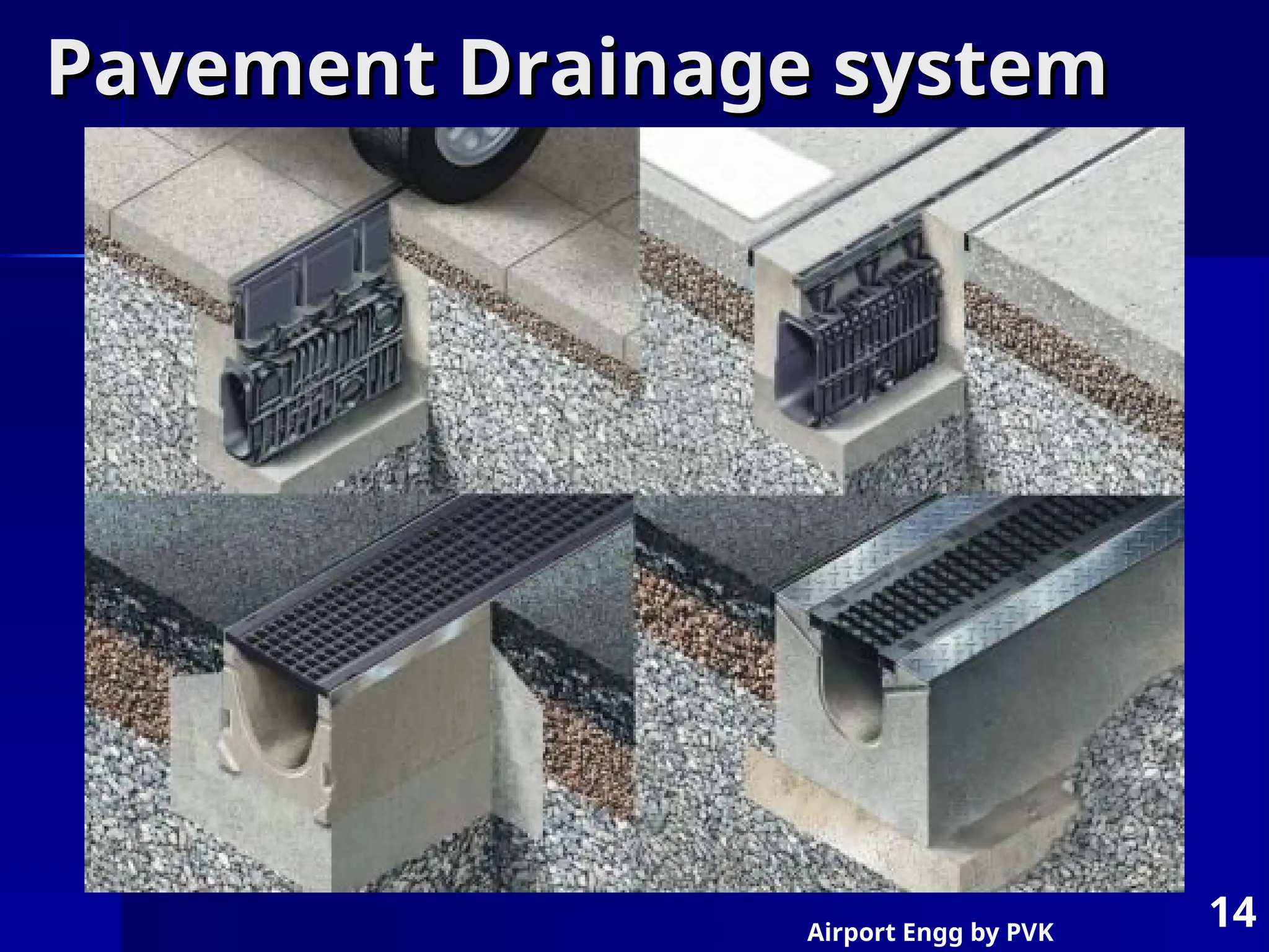
Pavement Drainage system
Pavement Drainage system
15.
Airport Engg byPVK
15
Component parts of Aircraft
Component parts of Aircraft
Engine –
Engine –
– Piston engine – low altitude, moderate speed
Piston engine – low altitude, moderate speed
– Turbo jet engine – baloone, take-compress-burn-expand-exhaust
Turbo jet engine – baloone, take-compress-burn-expand-exhaust
– Turbo Propulsion engine – mix
Turbo Propulsion engine – mix
– Ram jet – divergent convergent tube inside
Ram jet – divergent convergent tube inside
– Rocket engine – own oxygen supply
Rocket engine – own oxygen supply
Propeller – two blades – forces air inside at high speed
Propeller – two blades – forces air inside at high speed
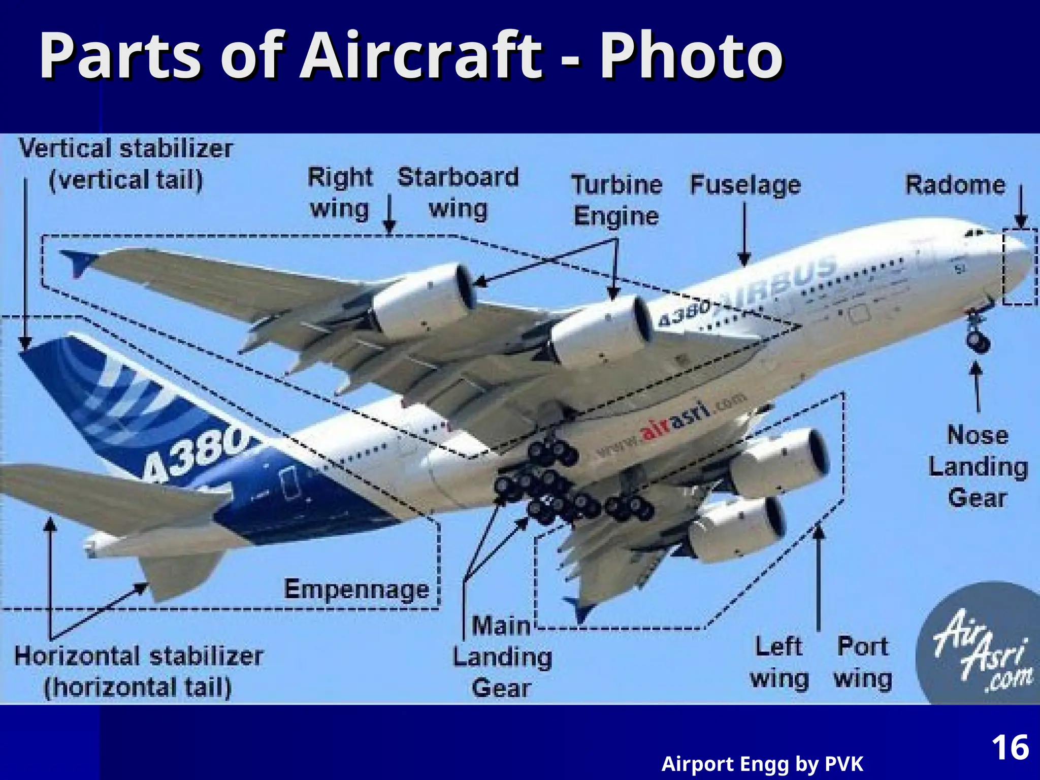
Fuselage – body containing power plant, fuel, cockpit, pasengers,
Fuselage – body containing power plant, fuel, cockpit, pasengers,
cargo etc. – aerogenic shape
cargo etc. – aerogenic shape
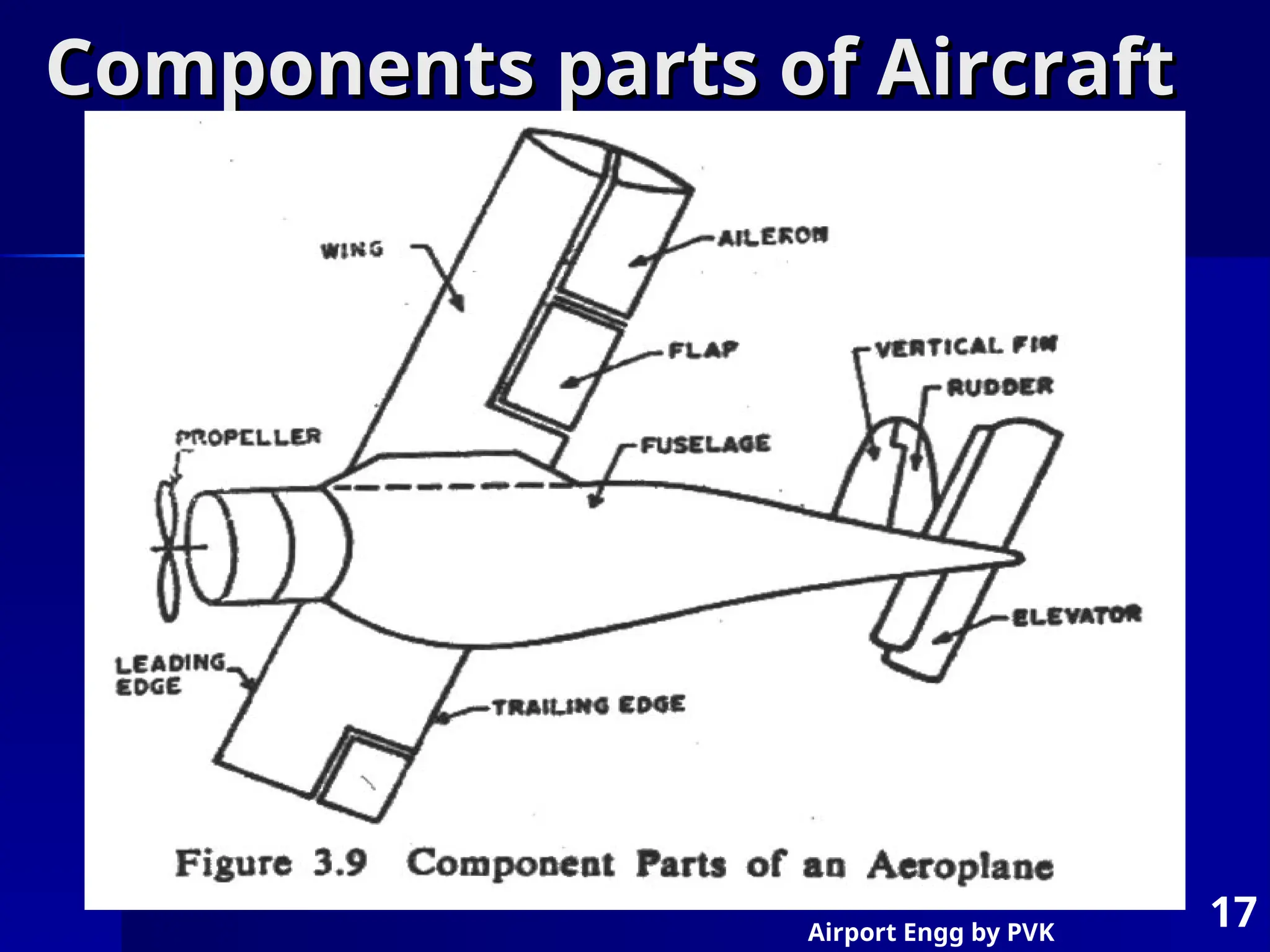
Wings – Aeilron, leading edge, trailing edge, flight path, angle of
Wings – Aeilron, leading edge, trailing edge, flight path, angle of
incidence, camber, Aerofoil.
incidence, camber, Aerofoil.
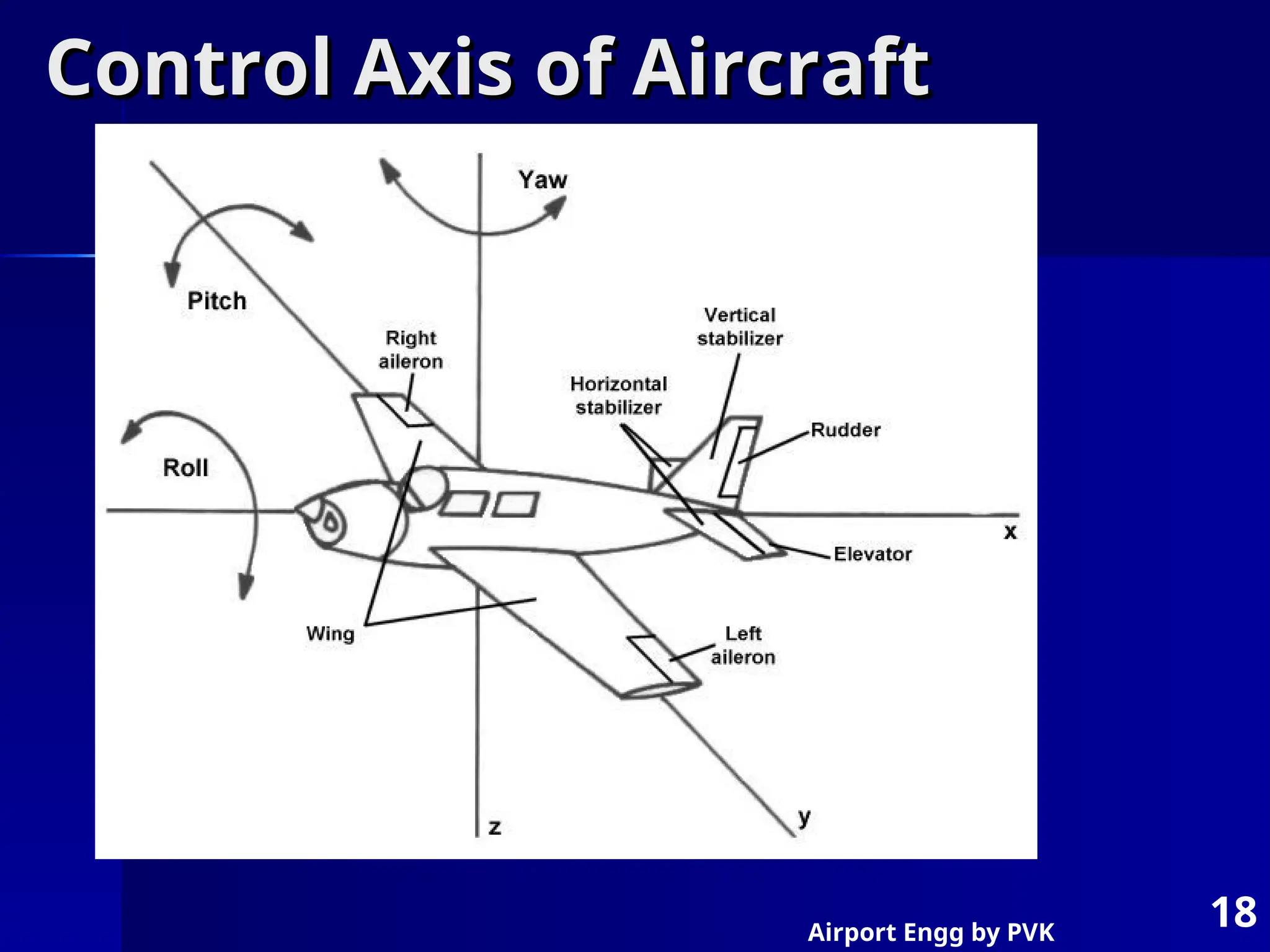
Three controls
Three controls
– Elevator – up / down / 50
Elevator – up / down / 500
0
/ 60
/ 600
0
/ at tail plane
/ at tail plane
– Rudder – right / left / 30
Rudder – right / left / 300
0
/
/
– Aileron – Tilting 45
Aileron – Tilting 450
0
/
/
Flaps – under wings – like aileron
Flaps – under wings – like aileron
Trycycle undercarriage – to absorb landing shocks, to enable
Trycycle undercarriage – to absorb landing shocks, to enable
movement on ground,
movement on ground,
16.
Airport Engg byPVK
16
Parts of Aircraft - Photo
Parts of Aircraft - Photo
17.
Airport Engg byPVK
17
Components parts of Aircraft
Components parts of Aircraft
18.
Airport Engg byPVK
18
Control Axis of Aircraft
Control Axis of Aircraft
19.
Airport Engg byPVK
19
Aircraft Parts and functions
Aircraft Parts and functions
20.
Airport Engg byPVK
20
Aircraft Component Parts - Plan
Aircraft Component Parts - Plan
21.
Airport Engg byPVK
21
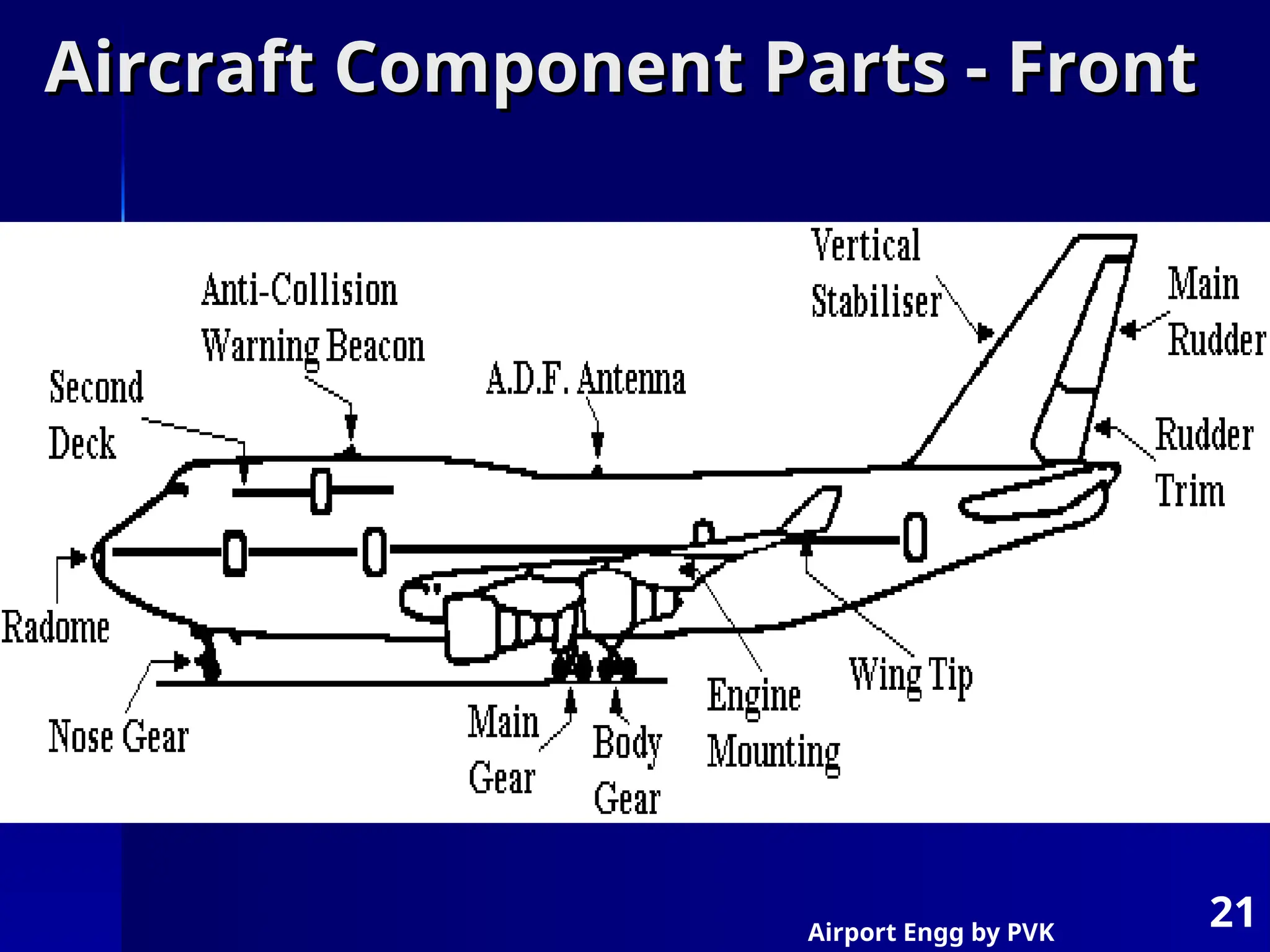
Aircraft Component Parts - Front
Aircraft Component Parts - Front
22.
Airport Engg byPVK
22
Aircraft Characteristics
Aircraft Characteristics
Type of propulsion
Type of propulsion
Size of aircraft
Size of aircraft
Min turning radius
Min turning radius
Min circling radius
Min circling radius
Speed of aircraft
Speed of aircraft
Capacity of aircraft
Capacity of aircraft
Aircraft weight and wheel configuration
Aircraft weight and wheel configuration
Jet blast
Jet blast
Fuel spillage
Fuel spillage
Noise
Noise
23.
Airport Engg byPVK
23
Airport Obstructions
Airport Obstructions
Zoning Laws -
Zoning Laws -
Classification of Obstructions
Classification of Obstructions
– a) objects protruding above imaginary surface
a) objects protruding above imaginary surface
– b) object exceeding limiting heights in approach zone
b) object exceeding limiting heights in approach zone
and turning zones
and turning zones
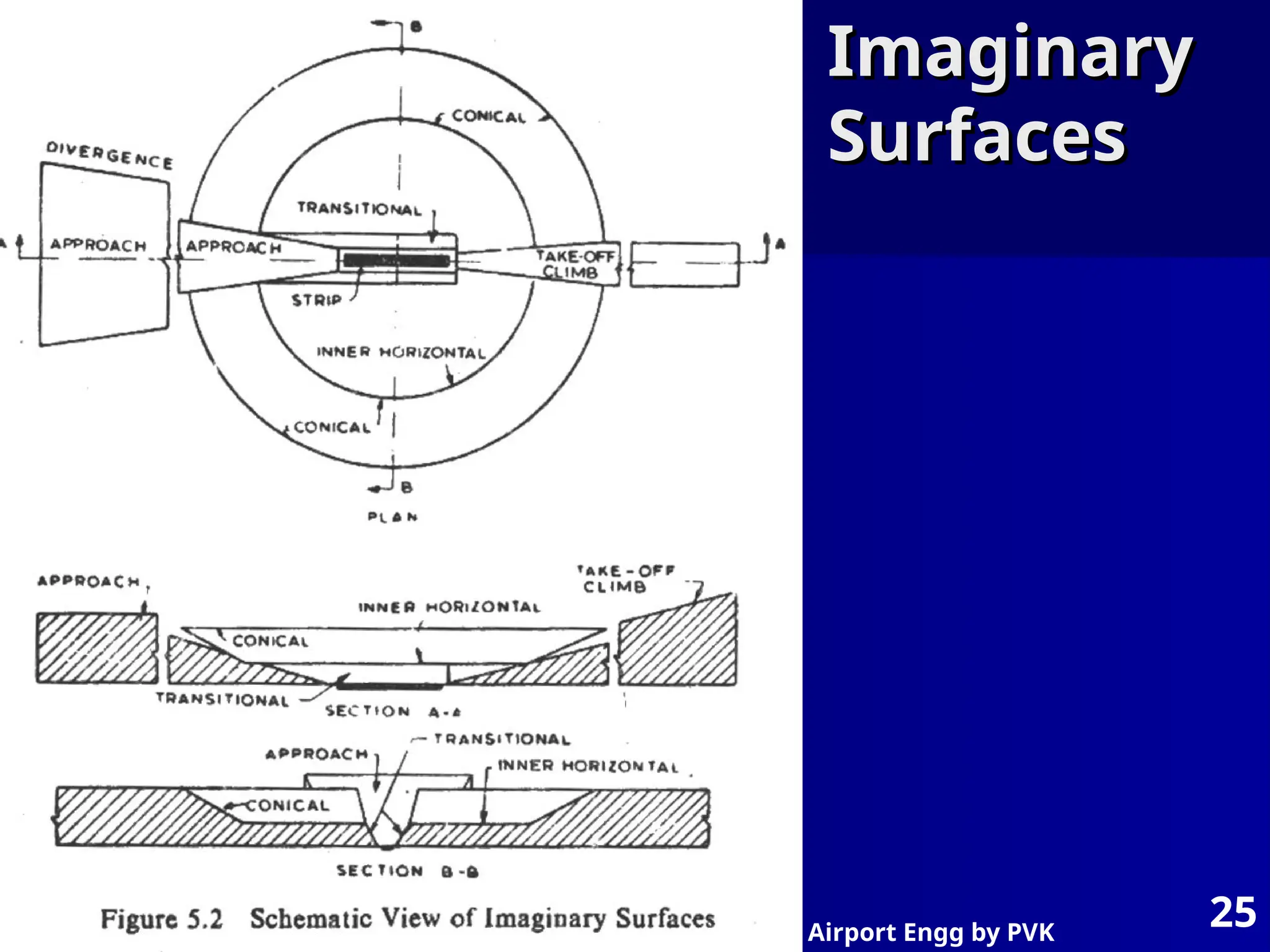
Imaginary surfaces
Imaginary surfaces
– Take-off climb surface
Take-off climb surface
– Approach surface
Approach surface
– Inner horizontal surface
Inner horizontal surface
– Conical surface
Conical surface
– Transitional surface
Transitional surface
– Outer horizontal surface
Outer horizontal surface
Airport Engg byPVK
26
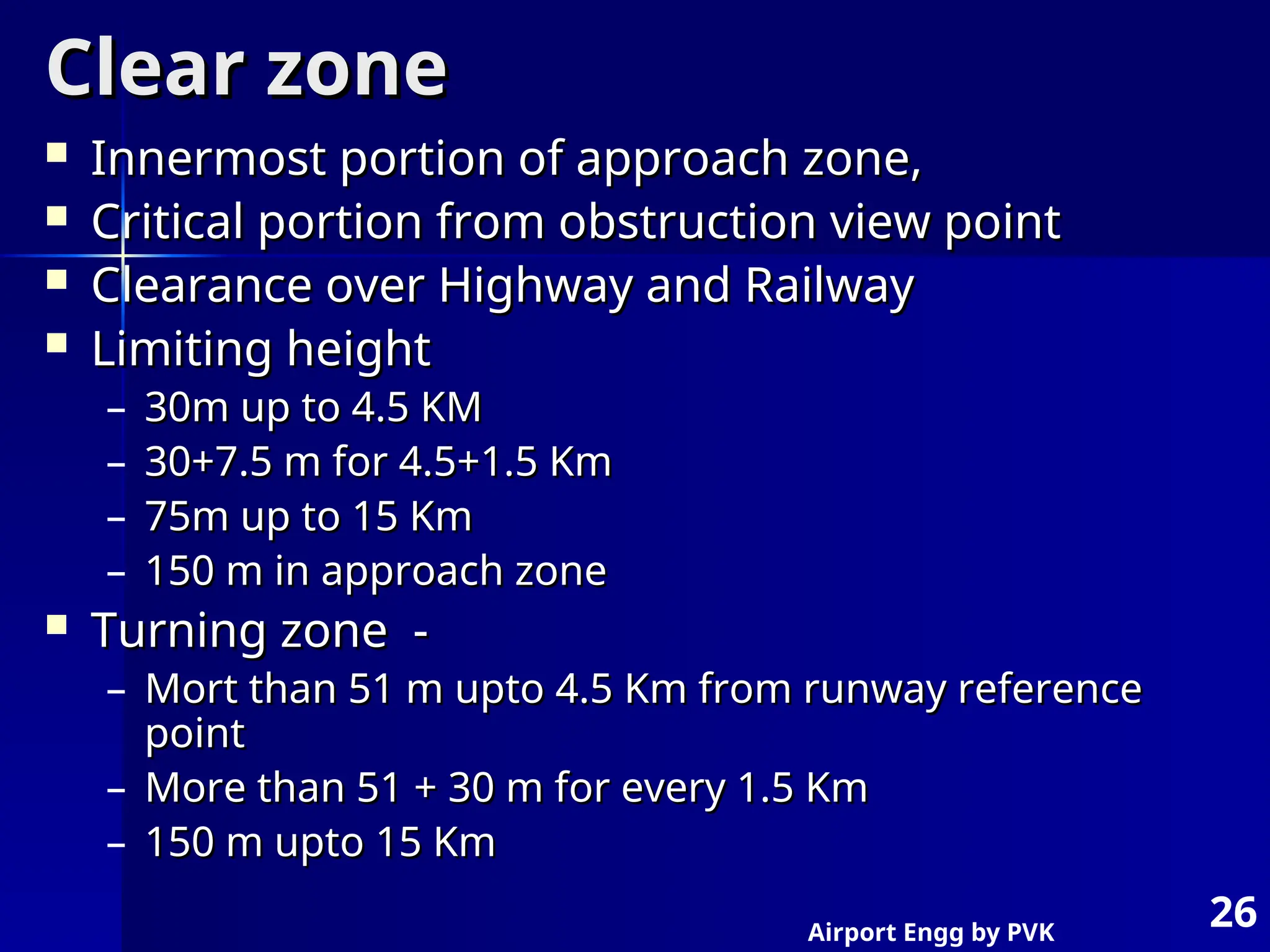
Clear zone
Clear zone
Innermost portion of approach zone,
Innermost portion of approach zone,
Critical portion from obstruction view point
Critical portion from obstruction view point
Clearance over Highway and Railway
Clearance over Highway and Railway
Limiting height
Limiting height
– 30m up to 4.5 KM
30m up to 4.5 KM
– 30+7.5 m for 4.5+1.5 Km
30+7.5 m for 4.5+1.5 Km
– 75m up to 15 Km
75m up to 15 Km
– 150 m in approach zone
150 m in approach zone
Turning zone -
Turning zone -
– Mort than 51 m upto 4.5 Km from runway reference
Mort than 51 m upto 4.5 Km from runway reference
point
point
– More than 51 + 30 m for every 1.5 Km
More than 51 + 30 m for every 1.5 Km
– 150 m upto 15 Km
150 m upto 15 Km
Airport Engg byPVK
28
Clearance Over Highway & Railway
Clearance Over Highway & Railway
29.
Airport Engg byPVK
29
Approach Zone Profile for Runway
Approach Zone Profile for Runway
30.
Airport Engg byPVK
30
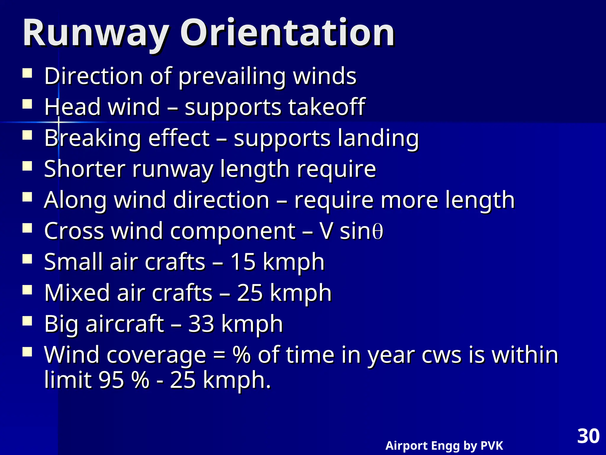
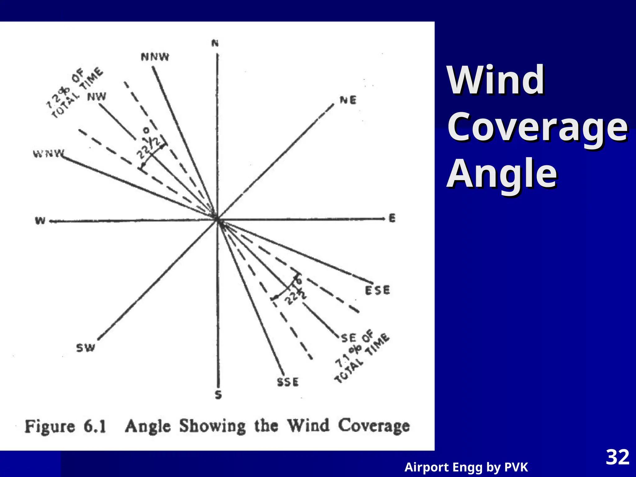
Runway Orientation
Runway Orientation
Direction of prevailing winds
Direction of prevailing winds
Head wind – supports takeoff
Head wind – supports takeoff
Breaking effect – supports landing
Breaking effect – supports landing
Shorter runway length require
Shorter runway length require
Along wind direction – require more length
Along wind direction – require more length
Cross wind component – V sin
Cross wind component – V sin
Small air crafts – 15 kmph
Small air crafts – 15 kmph
Mixed air crafts – 25 kmph
Mixed air crafts – 25 kmph
Big aircraft – 33 kmph
Big aircraft – 33 kmph
Wind coverage = % of time in year cws is within
Wind coverage = % of time in year cws is within
limit 95 % - 25 kmph.
limit 95 % - 25 kmph.
31.
Airport Engg byPVK
31
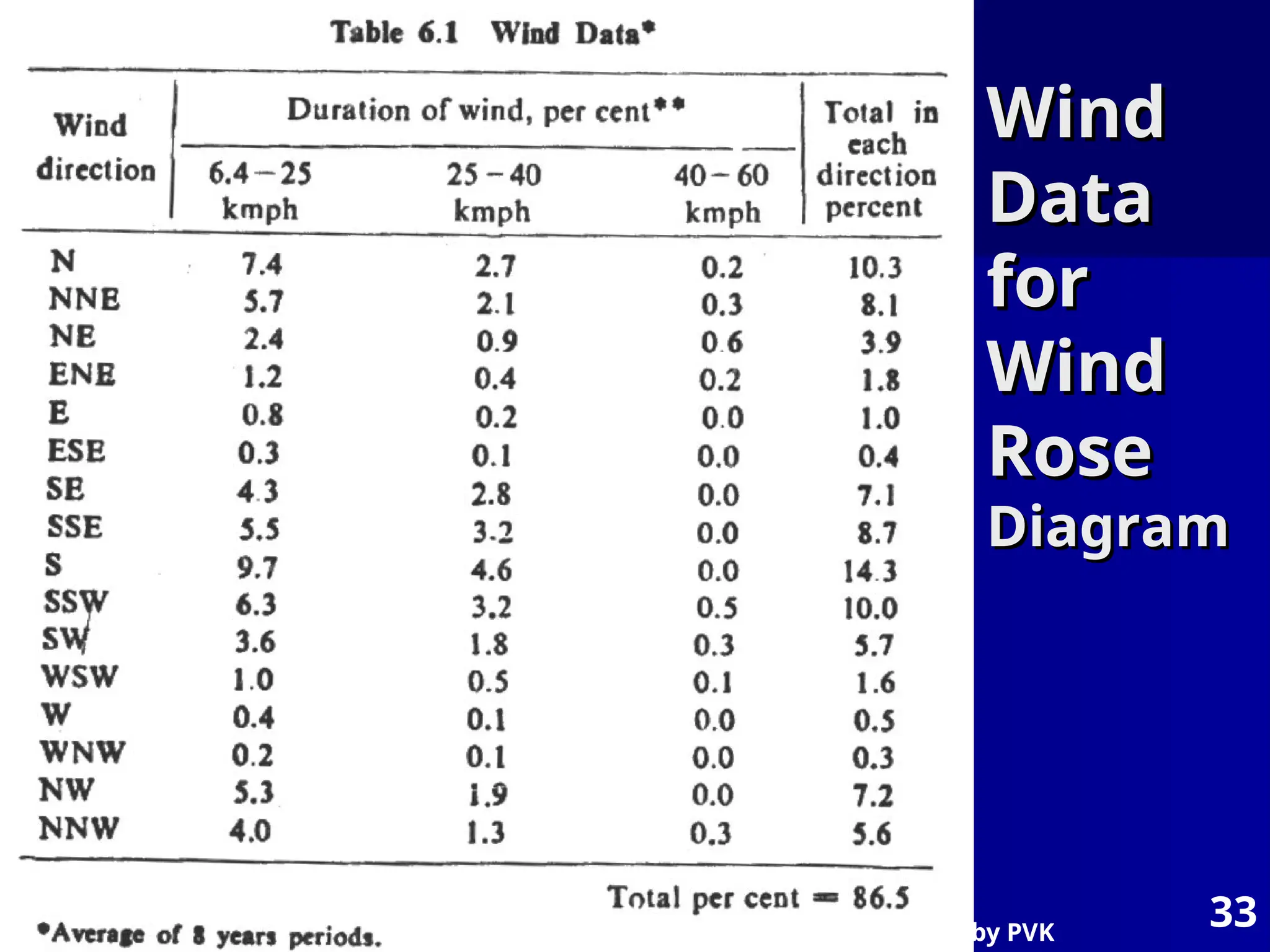
Wind rose Diagram
Wind rose Diagram
The wind data – direction, duration & intensity
The wind data – direction, duration & intensity
are graphically represented by wind rose
are graphically represented by wind rose
diagram.
diagram.
5 to 10 years
5 to 10 years
Analyzing wind data for orientation of runway
Analyzing wind data for orientation of runway
Direction, duration in %, total % in each
Direction, duration in %, total % in each
direction
direction
Type – 1, type -2
Type – 1, type -2
Wind coverage 2.5
Wind coverage 2.50
0
2
2
Obstructions, excessive grading, Noise nuisance
Obstructions, excessive grading, Noise nuisance
Airport Engg byPVK
33
Wind
Wind
Data
Data
for
for
Wind
Wind
Rose
Rose
Diagram
Diagram
34.
Airport Engg byPVK
34
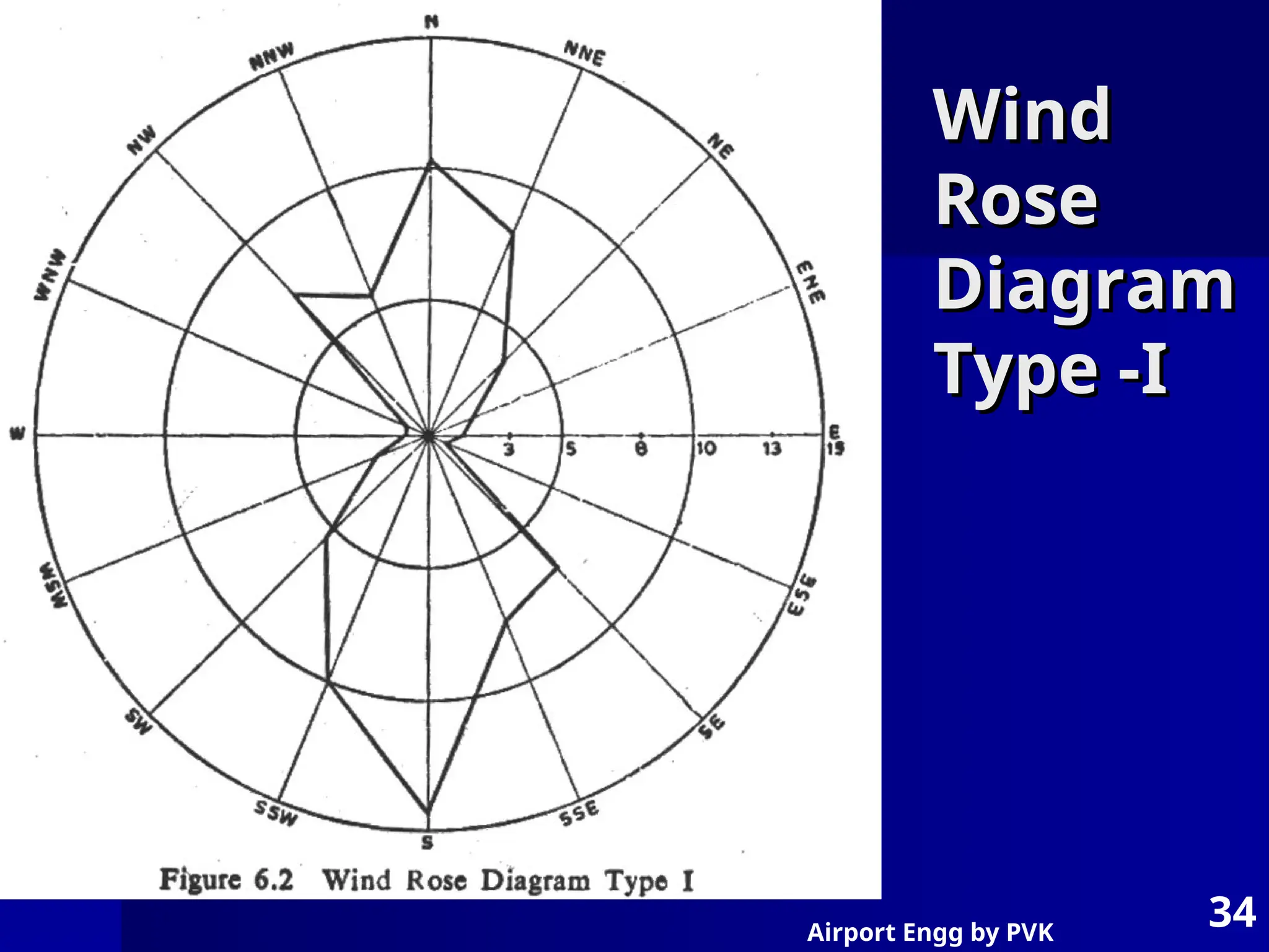
Wind
Wind
Rose
Rose
Diagram
Diagram
Type -I
Type -I
35.
Airport Engg byPVK
35
Wind Rose
Wind Rose
Diagram
Diagram
Type-II
Type-II
36.
Airport Engg byPVK
36
Basic runway length
Basic runway length
Assumptions
Assumptions
i) airport altitude is at sea level
i) airport altitude is at sea level
Temp at airport is standard 15 0
Temp at airport is standard 15 0
Runway is leveled in longitudional direction
Runway is leveled in longitudional direction
No wind is blowing on runway
No wind is blowing on runway
Aircraft is loaded to its full loading capacity
Aircraft is loaded to its full loading capacity
There is no wind blowing enroute to
There is no wind blowing enroute to
destination city
destination city
Enroute temperature is standard
Enroute temperature is standard
37.
Airport Engg byPVK
37
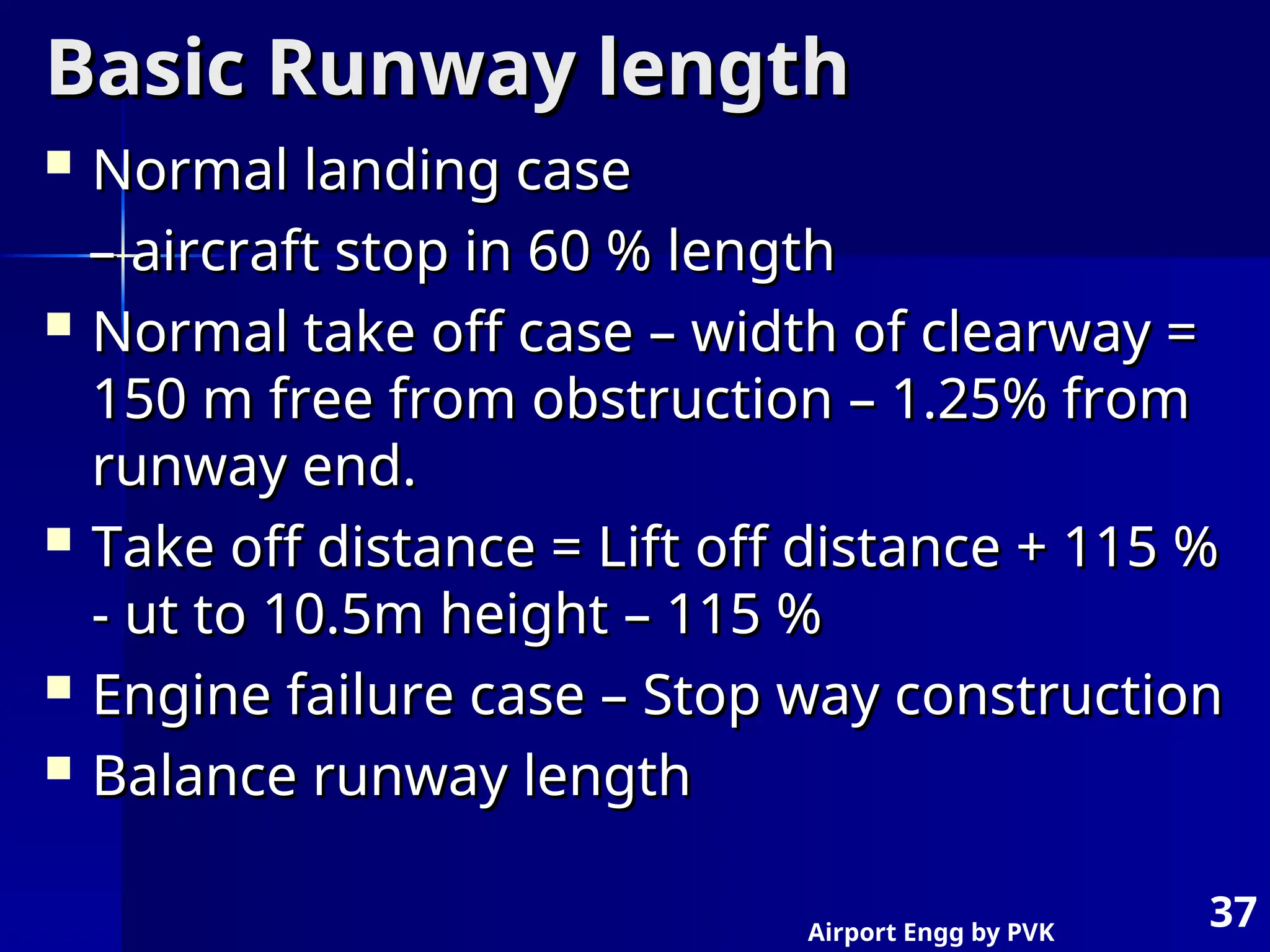
Basic Runway length
Basic Runway length
Normal landing case
Normal landing case
–
– aircraft stop in 60 % length
aircraft stop in 60 % length
Normal take off case – width of clearway =
Normal take off case – width of clearway =
150 m free from obstruction – 1.25% from
150 m free from obstruction – 1.25% from
runway end.
runway end.
Take off distance = Lift off distance + 115 %
Take off distance = Lift off distance + 115 %
- ut to 10.5m height – 115 %
- ut to 10.5m height – 115 %
Engine failure case – Stop way construction
Engine failure case – Stop way construction
Balance runway length
Balance runway length
38.
Airport Engg byPVK
38
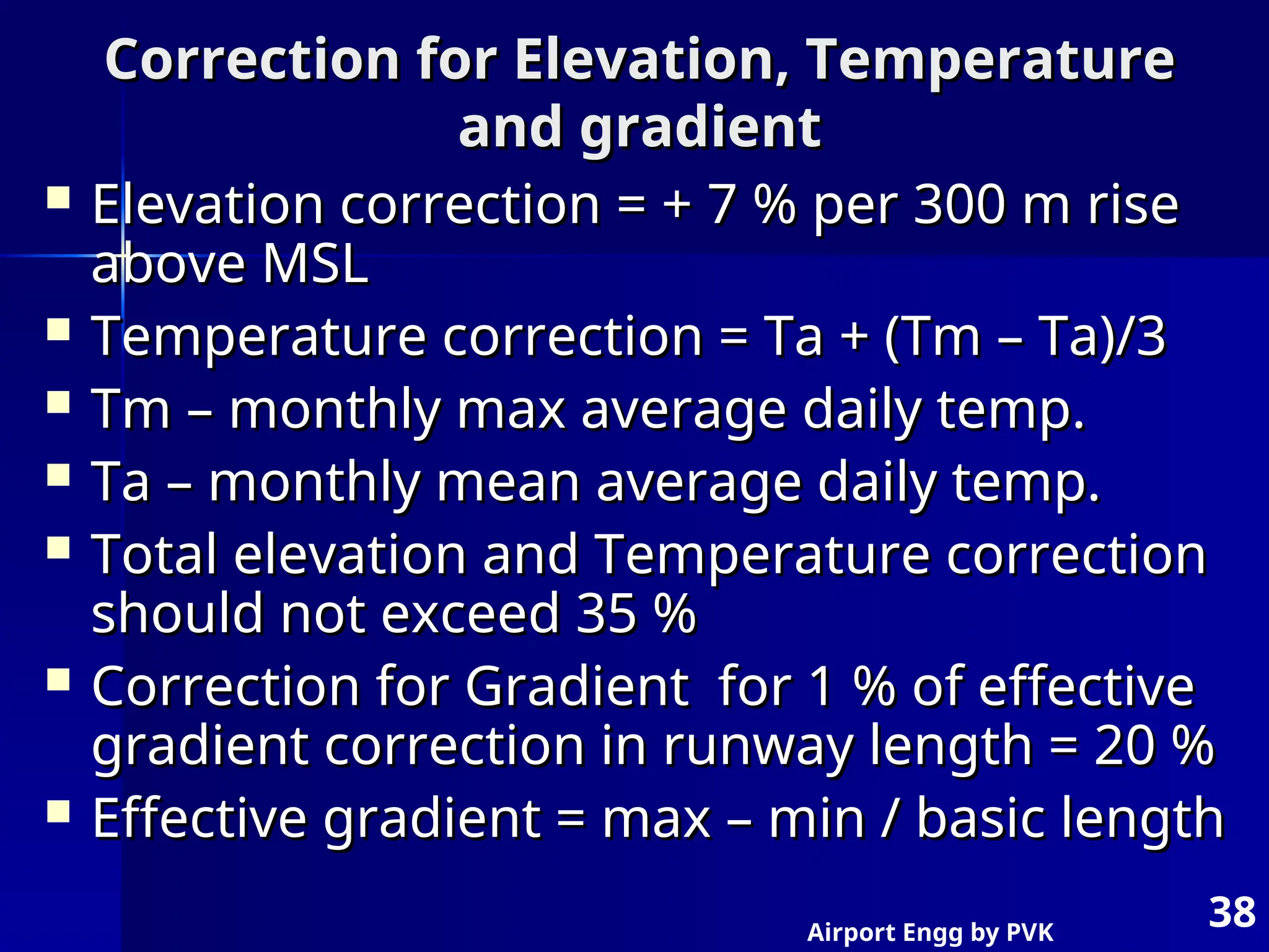
Correction for Elevation, Temperature
Correction for Elevation, Temperature
and gradient
and gradient
Elevation correction = + 7 % per 300 m rise
Elevation correction = + 7 % per 300 m rise
above MSL
above MSL
Temperature correction = Ta + (Tm – Ta)/3
Temperature correction = Ta + (Tm – Ta)/3
Tm – monthly max average daily temp.
Tm – monthly max average daily temp.
Ta – monthly mean average daily temp.
Ta – monthly mean average daily temp.
Total elevation and Temperature correction
Total elevation and Temperature correction
should not exceed 35 %
should not exceed 35 %
Correction for Gradient for 1 % of effective
Correction for Gradient for 1 % of effective
gradient correction in runway length = 20 %
gradient correction in runway length = 20 %
Effective gradient = max – min / basic length
Effective gradient = max – min / basic length