SlideShare a Scribd company logo
1 of 103
Download to read offline
11–76
                                                     FUEL   –   COMMON RAIL ASSY (1CD–FTV)


COMMON RAIL ASSY (1CD–FTV)
                                                                                                           110UB–01


COMPONENTS


                                              Clip


                                                                   Ratainer
        8.0 (82, 71 in.Vlbf)
                                                                          Radiator Support Opening Cover


                       Engine Cover No. 1


                 6.0 (61, 53 in.Vlbf)


  Radiator Reserve
  Tank Assy


    N·m (kgf·cm, ft·lbf) : Specified torque
                                                                                                            A79437


AVENSIS REPAIR MANUAL (RM1018E)
11–77
                                                 FUEL   –   COMMON RAIL ASSY (1CD–FTV)


                                                                     * 31 (316, 23)
                                                                      34 (347, 25)


                                                                                       5.0 (51, 44 in.Vlbf)


                                                                                          Injection Pipe Clamp No. 2

                                                                                         z Injection Pipe Sub–assy
                       z Fuel Inlet Pipe Sub–assy

                                * 31 (316, 23)
                                 34 (347, 25)
                                                                                * 31 (316, 23)
                                                                                 34 (347, 25)


                                                                                            Intake Manifold
                                                                                            Insulator No. 1
                                                               Common Rail Assy


                                                                                                     5.0 (51, 44 in.Vlbf)

                                                                                      43 (438, 32)

                                                             Fuel Hose No. 4


   N·m (kgf·cm, ft·lbf) : Specified torque
  z Non–reusable part
  * Use SST
                                                                                                                            A79438


AVENSIS REPAIR MANUAL (RM1018E)
11–78
                                              FUEL    –   COMMON RAIL ASSY (1CD–FTV)
                                                                                                           110UC–01


REPLACEMENT
1.      DRAIN ENGINE COOLANT (See page 16–44)
2.      REMOVE RADIATOR SUPPORT OPENING COVER
3.      REMOVE ENGINE COVER NO.1
(a)     Remove the 5 nuts and the engine cover.
4.      REMOVE RADIATOR RESERVE TANK ASSY (See page 16–50)


                                            5.    REMOVE FUEL INLET PIPE SUB–ASSY
                                            NOTICE:
                                            After removing the fuel inlet pipe, cover the common rail
                                            and the injection pump with vinyl tape to prevent dust from
                                            being introduced.
                                            (a) Using SST, remove the fuel inlet pipe from the common
        SST
                                                  rail.
                                                  SST 09023–12700
                                   A79148   (b) Using SST, remove the fuel inlet pipe from the injection
                                                  pump.
                                                  SST 09023–12700


                                            6.     REMOVE INJECTION PIPE SUB–ASSY NO.1
                                            (a)    Remove the 2 nuts and the 2 upper infection pipe clamps
                                                   from the intake manifold.
                                            (b)    Using SST, remove the injection pipe from the common
                                                   rail side.
                                                   SST 09023–12700
         SST                                (c)    Using SST, remove the injection pipe from the injector
                                                   side.
                                   A79143          SST 09023–12700
                                            (d)    After removing the fuel pipe, to prevent dust or foreign ob-
                                                   jects from being introduced, cover the common rail with
                                                   vinyl tape and protect the injector inlet with a vinyl or plas-
                                                   tic bag.
7.      REMOVE INJECTION PIPE SUB–ASSY            NO.2
        SST 09023–12700
HINT:
Perform the same procedures as injection pipe No. 1.
8.    REMOVE INJECTION PIPE SUB–ASSY NO.3
      SST 09023–12700
HINT:
Perform the same procedures as injection pipe No. 1.


 AVENSIS REPAIR MANUAL (RM1018E)
11–79
                                                FUEL   –   COMMON RAIL ASSY (1CD–FTV)

9.    REMOVE INJECTION PIPE SUB–ASSY NO.4
      SST 09023–12700
HINT:
Perform the same procedures as injection pipe No. 1.
10. DISCONNECT FUEL HOSE NO.4
(a) Disconnect the fuel hose from the common rail.
11. REMOVE INTAKE MANIFOLD INSULATOR NO.1 (See page 11–69)


                                              12.   REMOVE COMMON RAIL ASSY
                                              (a)   Disconnect the engine wire connector from the bracket.
                                              (b)   Remove the 2 bolts and the common rail.


                                     A79154


13.   INSTALL COMMON RAIL ASSY
      Torque: 43 NVm (438 kgfVcm, 32 ftVlbf)
14.   INSTALL INTAKE MANIFOLD INSULATOR NO.1 (See page 11–69)


                                              15. INSTALL INJECTION PIPE SUB–ASSY NO.1
                               30 cm          NOTICE:
                               (11.81 in.)     S  In case of having the common rail replaced, must re-
                                                  place the injection pipes, too.
                                               S  When assembling the pipes, perform the operation
       SST                                        with the engine cold under room temperature.
                                              (a) Remove the vinyl or the plastic bag from the injector and
                                                  vinyl tape from the common rail.
                                     A79147   (b) Temporarily install the injection pipe.


 AVENSIS REPAIR MANUAL (RM1018E)
11–80
                                                FUEL   –   COMMON RAIL ASSY (1CD–FTV)

                                           (c)     Using SST, tighten the nut of the injection pipe to the com-
                                                   mon rail side.
                                                   SST 09023–12700
                                                   Torque:
                                                   42 NVm (428 kgfVcm, 31 ftVlbf) for a used pipe using SST
                                                   46 NVm (469 kgfVcm, 34 ftVlbf) for a used pipe not using
                                                   SST
                                                   31 NVm (316 kgfVcm, 23 ftVlbf) for a new pipe using SST
                                                   34 NVm (347 kgfVcm, 25 ftVlbf) for a new pipe not using
                                                   SST
                                           HINT:
                                            S      Use a torque wrench with a fulcrum length of 30 cm
                                                   (11.81 in.)
                                            S      Check if the used pipe has deflection or is installed prop-
                                                   erly after injection pipe is reassembled. If there is deflec-
                                                   tion or if it can not be installed properly, replace the used
                                                   pipe with a new pipe.
                                           (d)     Using SST, tighten the nut of the injection pipe to the injec-
                                                   tor side.
                                                   SST 09023–12700
                                                   Torque:
                                                   42 NVm (428 kgfVcm, 31 ftVlbf) for a used pipe using SST
                                                   46 NVm (469 kgfVcm, 34 ftVlbf) for a used pipe not using
                                                   SST
                                                   31 NVm (316 kgfVcm, 23 ftVlbf) for a new pipe using SST
                                                   34 NVm (347 kgfVcm, 25 ftVlbf) for a new pipe not using
                                                   SST
                                           HINT:
                                            S
                                         Use a torque wrench with a fulcrum length of 30 cm
                                         (11.81 in.)
                                      S  Check if the used pipe has deflection or is installed prop-
                                         erly after injection pipe is reassembled. If there is deflec-
                                         tion or if it can not be installed properly, replace the used
                                         pipe with a new pipe.
                                     (e) Install the 2 upper injection pipe clamps with the 2 nuts.
                                         Torque: 5.0 NVm (51 kgfVcm, 44 in.Vlbf)
16.     INSTALL INJECTION PIPE SUB–ASSY NO.2
        SST 09023–12700
HINT:
Perform the same procedures as injection pipe No. 1.
17. INSTALL INJECTION PIPE SUB–ASSY NO.3
      SST 09023–12700
HINT:
Perform the same procedures as injection pipe No. 1.
18. INSTALL INJECTION PIPE SUB–ASSY NO.4
      SST 09023–12700
HINT:
Perform the same procedures as injection pipe No. 1.


AVENSIS REPAIR MANUAL (RM1018E)
11–81
                                               FUEL   –   COMMON RAIL ASSY (1CD–FTV)

                                           19. INSTALL FUEL INLET PIPE SUB–ASSY
                             30 cm         NOTICE:
                             (11.81 in.)    S    In case of having the common rail replaced, must re-
                                                 place fuel inlet pipe, too.
                                            S    When assembling the pipe, perform the operation
       SST                                       with the engine cold under room temperature.
                                           (a) Temporarily install the fuel inlet pipe.
                                           (b) Using SST, tighten the nut of the fuel inlet pipe to the com-
                                    A79149       mon rail side.
                                                 SST 09023–12700
                                                 Torque:
                                                 42 NVm (428 kgfVcm, 31 ftVlbf) for a used pipe using SST
                                                 46 NVm (469 kgfVcm, 34 ftVlbf) for a used pipe not using
                                                 SST
                                                 31 NVm (316 kgfVcm, 23 ftVlbf) for a new pipe using SST
                                                 34 NVm (347 kgfVcm, 25 ftVlbf) for a new pipe not using
                                                 SST
                                           HINT:
                                            S    Use a torque wrench with a fulcrum length of 30 cm
                                                 (11.81 in.)
                                            S    Check if the used pipe has deflection or is installed prop-
                                                 erly after inlet pipe is reassembled. If there is deflection
                                                 or if it can not be installed properly, replace the used pipe
                                                 with a new pipe.
                                           (c) Using SST, tighten the nut of the fuel inlet pipe to the injec-
                                                 tion pump side.
                                                 SST 09023–12700
                                                 Torque:
                                                 42 NVm (428 kgfVcm, 31 ftVlbf) for a used pipe using SST
                                                 46 NVm (469 kgfVcm, 34 ftVlbf) for a used pipe not using
                                                 SST
                                                 31 NVm (316 kgfVcm, 23 ftVlbf) for a new pipe using SST
                                                 34 NVm (347 kgfVcm, 25 ftVlbf) for a new pipe not using
                                                 SST
                                           HINT:
                                            S    Use a torque wrench with a fulcrum length of 30 cm
                                                 (11.81 in.)
                                            S    Check if the used pipe has deflection or is installed prop-
                                                 erly after inlet pipe is reassembled. If there is deflection
                                                 or if it can not be installed properly, replace the used pipe
                                                 with a new pipe.
20.   INSTALL RADIATOR RESERVE TANK ASSY (See page 16–50)
21.   INSTALL ENGINE COVER NO.1
      Torque: 8.0 NVm (82 kgfVcm, 71 in.Vlbf)
22.   ADD ENGINE COOLANT (See page 16–44)
23.   CHECK FOR ENGINE COOLANT LEAKS (See page 16–37)
24.   CHECK FOR FUEL LEAKS (See page 11–60)


AVENSIS REPAIR MANUAL (RM1018E)
11–82
                                                FUEL   –   FUEL FILTER ASSY (1CD–FTV)


FUEL FILTER ASSY (1CD–FTV)
                                                                                                           110UD–01


REPLACEMENT
1.      REMOVE AIR CLEANER ASSY
(a)     Disconnect the connector.
(b)     Remove the air cleaner cap with the air cleaner hose.
(c)     Remove the air cleaner filter element.
(d)     Remove the 3 bolts and the air cleaner case.
2.      REMOVE FUEL FILTER ASSY
(a)     Disconnect the 2 fuel hose from the fuel filter. (STD or COLD)
(b)     Disconnect the 3 fuel hose from the fuel filter. (W/ ADDTIONAL HEATER)
(c)     Disconnect the 2 connectors.
(d)     Remove the 2 bolts and the fuel filter.
3.      DRAIN FUEL
(a)     Loosen the drain plug, and drain the fuel from the fuel filter.


                                              4.   REMOVE LEVEL WARNING SWITCH
                                              (a) Clamp the fuel filter in a soft jaw vise.
                                              (b) Using pliers, remove the level warning switch.
                                              NOTICE:
                                              Be careful not to damage the level warning switch.


                                     A79188


                                              5.    REMOVE FUEL FILTER ELEMENT
                                              (a)   Using SST, remove the fuel filter element.
                                                    SST 09228–64030


            SST                      A80091


                                              6.    INSTALL FUEL FILTER ELEMENT
                                              (a)   Check and clean the fuel filter installation surface.
                                              (b)   Apply fuel to a gasket of a new fuel filter element.
                                              (c)   Lightly screw the fuel filter element into place, and tighten
                                                    it until the gasket comes into contact with the seat.
                                              (d)   Tighten it additional 3/4 turn by hand.


                                     A79190


 AVENSIS REPAIR MANUAL (RM1018E)
11–83
                                                 FUEL   –   FUEL FILTER ASSY (1CD–FTV)

7.    INSTALL LEVEL WARNING SWITCH
(a)   Install a new O–ring to the level warning switch.
(b)   Apply fuel to the O–ring of the level warning switch.
(c)   Install the level warning switch to the fuel filter by hand.
8.    INSTALL FUEL FILTER ASSY
      Torque: 18 NVm (178 kgfVcm, 13 ftVlbf)
9.    INSTALL AIR CLEANER ASSY
      Torque: 7.0 NVm (71 kgfVcm, 62 in.Vlbf)
10.   CHECK FOR FUEL LEAKS (See page 11–60)


 AVENSIS REPAIR MANUAL (RM1018E)
11–24
                                              FUEL      –   FUEL INJECTOR ASSY (1AZ–FE)


FUEL INJECTOR ASSY (1AZ–FE)
                                                                                                         110U0–01


COMPONENTS


                                             7.0 (71, 62 in.Vlbf)


                                                              Engine Cover Sub–assy
                                                              No. 1

                                                               Fuel Vapor Feed Hose
                                                                                                   VSV
                                                                                                   Connector


                                                                                               Mass Air Flow
                                                                                               Meter Connector

                                                     Air Cleaner Cap
                                                     Sub–assy


                                                                        Fuel Vapor Feed Hose
                                                                        No. 2


   N·m (kgf·cm, ft·lbf) : Specified torque
                                                                                                          A79730


AVENSIS REPAIR MANUAL (RM1018E)
11–25
                                                 FUEL   –   FUEL INJECTOR ASSY (1AZ–FE)


            z Fuel Injector O–ring                                          Fuel Injector
                                                                            Connector
           Fuel Injector Assy


                                                                    20 (204, 15)

                             Fuel Delivery Pipe Sub–assy


                           EFI Fuel Pipe Clamp
                                                                                            Delivery Pipe No. 1
                                                                                            Spacer
                        Fuel Tube Sub–assy
                                                                                    z Injector Vibration Insulator


                                                                                            Ventilation Hose No. 2


  N·m (kgf·cm, ft·lbf) : Specified torque
 z Non–reusable part                                                                                              A77907


AVENSIS REPAIR MANUAL (RM1018E)
11–26
                                                      FUEL   –   FUEL INJECTOR ASSY (1AZ–FE)
                                                                                                          110U1–01


REPLACEMENT
1.      DISCHARGE FUEL SYSTEM PRESSURE (See page 11–15)
2.      REMOVE ENGINE COVER SUB–ASSY NO.1 (See page 10–26)
3.      REMOVE AIR CLEANER CAP SUB–ASSY (See page 10–26)

                                                    4.  DISCONNECT FUEL TUBE SUB–ASSY
                                                    (a) Remove the fuel pipe clamp.
                  Retainer                          (b) Using SST, disconnect the fuel tube.
                  (at 4 places)                         SST 09268–21010
                                  Fuel Pipe
                                                        (1) Assemble SST to the connection of the fuel tube as
                                  Clamp
                                                              shown in the illustration.
                                                        (2) Turn SST, align the retainers inside the connector
                                                              with SST into the connector.
                                                        (3) Push in the SST and the connector together to-
                                  Turn                        wards the fuel tube assembly.
                                                    NOTICE:
                                    SST              S  Check if there is any dirt or mud on the pipe and
                                                        around the connector before disconnecting them and
                                                        remove the dirt as necessary.
             Insert                                  S  Do not bent and twist the nylon tube.
                                                     S  When the connector and pipe are stuck, push and pull
                                                        the connector to free. Pull the connector out carefully.
                                                     S  Prevent the disconnected pipe and connector from
                                           A77908       being damaged and foreign objects from being
                                                        introduced, cover with a vinyl or plastic bag.

                  O–ring Retainer        Pipe


     Nylon Tube              Housing
                                           A76220


                                                    5.    REMOVE FUEL DELIVERY PIPE SUB–ASSY
                                                    (a)   Disconnect the ventilation hose.


                                           A77909


 AVENSIS REPAIR MANUAL (RM1018E)
11–27
                                                 FUEL   –   FUEL INJECTOR ASSY (1AZ–FE)

                                               (b)   Remove the 2 wire harness clamps.
                                               (c)   Disconnect the 4 fuel injector connectors.


                          (b)
                                (c)
                         (c)
               (b) (c)
             (c)
                                      A77910


                                               (d)  Remove the 2 bolts, and then remove the fuel delivery
                                                    pipe together with the 4 fuel injectors.
                                               NOTICE:
                                               Be careful not to drop the fuel injectors when removing the
                                               delivery pipe.


                                      A78437


         Delivery Pipe                         (e)   Remove the 2 delivery pipe No. 1 spacers and the 4 insu-
         No. 1 Spacer                                lators from the cylinder head.


                  Insulator
                                      A77911


                                               6.    REMOVE FUEL INJECTOR ASSY
                                               (a)   Pull out the 4 fuel injectors.


                                      A77912


                                               7.    INSTALL FUEL INJECTOR ASSY
                                               (a)   Apply a light coat of spindle oil or gasoline to new O–rings
                                                     and install them to each fuel injector.


                          New O–ring
                                      A78481


AVENSIS REPAIR MANUAL (RM1018E)
11–28
                                                FUEL   –   FUEL INJECTOR ASSY (1AZ–FE)

                                              (b) Apply a light coat of spindle oil or gasoline on the place
                   Turn                           where a fuel delivery pipe contacts the O–ring.
 Push                                         (c) Push the fuel injector while twisting it back and forth to
                                                  install it to the fuel delivery pipe.
                                              NOTICE:
                                               S  Be careful not to twist the O–ring.
                                               S  After installing the fuel injectors, check that they turn
                                                  smoothly. If not, reinstall it with a new O–ring.
                                     A77913


                                              8.     INSTALL FUEL DELIVERY PIPE SUB–ASSY
                                              (a)    Install 4 new insulators and the 2 delivery pipe No. 1
                                                     spacers to the cylinder head.
                                              (b) Place the fuel delivery pipe and the 4 fuel injectors togeth-
                                                     er to the cylinder head.
                            Turn
                                              NOTICE:
                                              Be careful not to drop the fuel injectors when installing the
                                              fuel delivery pipe.
                                     A77914   (c) Temporarily install 2 bolts which are used to secure the
                                                     fuel delivery pipe to the cylinder head.
                                              (d) Check that the fuel injectors rotate smoothly.
                                              If the fuel injectors do not rotate smoothly, the probable cause
                                              is incorrect installation of O–ring. Replace with the O–ring.
                                              (e) Tighten the 2 bolts.
                                                     Torque: 20 NVm (204 kgfVcm, 15 ftVlbf)
                                              (f)    Connect the 4 fuel injector connectors.
                                              (g) Install the 2 wire harness clamps.
                                              (h) Connect the ventilation hose.


                              Fuel Pipe       9.  CONNECT FUEL TUBE SUB–ASSY
                              Clamp           (a) Push in the connector to the pipe until it makes ”click”
                                                  sound.
                                              NOTICE:
                                               S  Check if there is any damage or foreign objects on the
                                                  connected part.
                                               S  After connecting, check if the connector and the pipe
                                  Push
                                                  are securely connected by pulling on them.
                                     A81621   (b) Install the fuel pipe clamp.

10.     INSTALL AIR CLEANER CAP SUB–ASSY
11.     CHECK FOR FUEL LEAKS (See page 11–19)
12.     INSTALL ENGINE COVER SUB–ASSY NO.1 (See page 10–26)


AVENSIS REPAIR MANUAL (RM1018E)
11–37
                                                     FUEL    –   FUEL INJECTOR ASSY (1AZ–FSE)


FUEL INJECTOR ASSY (1AZ–FSE)
                                                                                                                     110TC–01


COMPONENTS
                  x2
           Clip


                                          Engine Room Cover Side


                                     x4
                                              Clip
                                                                                                Retainer
                                                            Radiator Support Opening Cover


                                                 7.0 (71, 62 in.Vlbf)


                                                                 Engine Cover Sub–assy
                                                                 No. 1

                                                                        Fuel Vapor Feed Hose
                                                                                                               VSV
                                                                   1.5 (15, 13 in.Vlbf)
                                                                                                               Connector


                                                                                                           Mass Air Flow
                                                                                                           Meter Connector


                                                             Air Cleaner Cap
                                                             Sub–assy


   N·m (kgf·cm, ft·lbf) : Specified torque
                                                                                                                      A78507


AVENSIS REPAIR MANUAL (RM1018E)
11–38
                                                    FUEL   –   FUEL INJECTOR ASSY (1AZ–FSE)


                                                                     Throttle Motor Connector


                                             Throttle Body Assy


                                                                                                  x4


                                                                                        9.0 (90, 80 in.Vlbf)


                                z Throttle Body Gasket
                                     Water By–pass Hose No. 1                             Water By–pass Hose No. 2


                                                                                                               x4


                            Throttle Body Bracket                                                       21 (210, 15)

                                                                                                       Ground Terminal


                                                                                                    8.4 (86, 74 in.Vlbf)

                              Wire Harness Protector


                                                                         8.4 (86, 74 in.Vlbf)


   N·m (kgf·cm, ft·lbf) : Specified torque
  z Non–reusable part                                                                                                      A78508


AVENSIS REPAIR MANUAL (RM1018E)
11–39
                                                 FUEL       –   FUEL INJECTOR ASSY (1AZ–FSE)


                                                                                Fuel Tube Sub–assy


                                                                 z Gasket                            Fuel Pipe Clamp


                                              z Gasket


          25 (255, 18)


                                                                     33 (331, 24)
                                                                    Fuel Pressure Pulsation
  z Fuel Pump                          Fuel Pump Assy               Damper Assy
    Insulator
                                             30 (306, 22)


                                                                    Fuel Pipe Sub–assy No. 1

                                                                         9.0 (92, 80 in.Vlbf)

                                        Fuel Hose                           z Fuel Injector Back–up Ring No. 1
                                                                            z Fuel Injector Back–up Ring No. 2
                                                                            z O–ring
                                                                            z Fuel Injector Back–up Ring No. 3


                                                                                                             38 (388, 28 )


                                                                                                Engine Cover Bracket


  N·m (kgf·cm, ft·lbf) : Specified torque
  z Non–reusable part                                                                                                        A79577


AVENSIS REPAIR MANUAL (RM1018E)
11–40
                                                      FUEL    –   FUEL INJECTOR ASSY (1AZ–FSE)


                                                                                                    30 (306, 22)


        Union to Connector
        Tube Hose
                                                                                                                 30 (306, 22)


             Vacuum Hose


             Intake Manifold                                                                        Intake Manifold
             Insulator No. 1


                                                                                                         x2
                                                                                                                30 (306, 22)
                                                                     z Gasket


                                                             Intake Air Control Valve Assy


                                                   z Gasket

                                      9.5 (97, 84 in.Vlbf)


                                                                                                              9.8 (100, 7)


                                                Intake Manifold Insulator No. 2

                                                                                                              21 (210, 15)


                                                                                Surge Tank
                                                                                Stay No. 1


                                                                                    38 (388, 28)


                                                                  Engine Cover Bracket        Charcoal Canister Assy

   N·m (kgf·cm, ft·lbf) : Specified torque
   z Non–reusable part
                                                                                                                             A79597


AVENSIS REPAIR MANUAL (RM1018E)
11–41
                                                FUEL        –   FUEL INJECTOR ASSY (1AZ–FSE)


                                                                                                      z E–ring
                                                                                        z O–ring
                                                                       z Fuel Injector
                                                                         Back–up Ring No. 1


                                                                                               z Fuel Injector
                                                                                                 Back–up Ring No. 3

                                                                                       z Fuel Injector
                                                                                         Back–up Ring No. 2


                                                                       z Gasket


                                                                                Injector Assy

                                                                z Fuel Injector Seal


                                              13 (127, 9)


                                                                   Fuel Delivery
                                                                   Pipe Sub–assy


                                  Nozzle Holder Clamp


                                                                                     x5


                                                                            19 (194, 14)

   N·m (kgf·cm, ft·lbf) : Specified torque
   z Non–reusable part
                                                                                                                 A79598


AVENSIS REPAIR MANUAL (RM1018E)
11–10
                                                       FUEL    –     FUEL INJECTOR ASSY (1ZZ–FE/3ZZ–FE)


FUEL INJECTOR ASSY (1ZZ–FE/3ZZ–FE)
                                                                                                                           110TY–01


COMPONENTS
        1ZZ–FE:


                                 z Fuel Injector O–Ring

                                     Fuel Injector Assy
        3ZZ–FE:


                                 z Fuel Injector O–Ring                                               Clip
                                   z Fuel Injector Grommet
                                                                                                    7.0 (71, 62 in.·lbf)

                                       Fuel Injector Assy


               19 (189, 14)
                                             Cylinder Head Cover No. 2


                                                   Fuel Pipe Clamp No. 2


                                       Fuel Delivery Pipe
                                       Sub–assy
                                                                         Fuel Tube Sub–assy
 z Injector Vibration
   Insulator
                                                                   9.0 (91, 80 in.·lbf)


                              No. 1 Spacer


                                                              Ventilation Hose

                                                       Fuel Injector Connector


    N·m (kgf·cm, ft·lbf) : Specified torque
    z Non–reusable part                                                                                                     A78470


AVENSIS REPAIR MANUAL (RM1018E)
11–11
                                                       FUEL   –   FUEL INJECTOR ASSY (1ZZ–FE/3ZZ–FE)
                                                                                                           110TZ–01


REPLACEMENT
1.      DISCHARGE FUEL SYSTEM PRESSURE (See page 11–1)
2.      REMOVE CYLINDER HEAD COVER NO.2 (See page 10–9)


                                                     3.  SEPARATE FUEL TUBE SUB–ASSY
                                                     (a) Remove the fuel pipe clamp.
                          Retainer                   (b) Using SST, disconnect the fuel tube.
                          (at 4 places)                  SST 09268–21010
                                                         (1) Assemble SST to the connection of the fuel tube as
                                   Fuel Pipe                   shown in the illustration.
                                   Clamp                 (2) Turn SST, align the retainers inside the connector
                                                               with SST into the connector.
                                                         (3) Push in the SST and the connector together to-
                  Turn                                         wards the fuel tube assembly.
                                  SST                NOTICE:
                                                      S  Check if there is any dirt or mud on the pipe and
                                                         around the connector before disconnecting them and
                                                         remove the dirt as necessary.
                     Insert                           S  Do not bent and twist the nylon tube.
                                                      S  When the connector and pipe are stuck, push and pull
                                                         the connector to free. Pull the connector out carefully.
                                                      S  Prevent the disconnected pipe and connector from
                                            A78471       being damaged and foreign objects from being
                                                         introduced, cover with a vinyl or plastic bag.

                  O–ring Retainer         Pipe


     Nylon Tube               Housing
                                            A76220


                                                     4.    REMOVE FUEL DELIVERY PIPE SUB–ASSY
                                                     (a)   Disconnect the ventilation hose.


                                            A78472


 AVENSIS REPAIR MANUAL (RM1018E)
11–12
                                                   FUEL   –   FUEL INJECTOR ASSY (1ZZ–FE/3ZZ–FE)

                                                 (b)   Disconnect the 4 fuel injector connectors.
                (a)                              (c)   Remove the 3 wire harness clamps.
                      (a)
                            (a)
                                  (a)

          (b)
                  (b)
                                  (b)
                                        A78473


                                                 (d)   Remove the 3 bolts, and then remove the fuel delivery
                                                       pipe together with the 4 fuel injectors.
                                                 NOTICE:
                                                 Be careful not to drop the fuel injectors when removing the
                                                 fuel delivery pipe.


                                        A78480


                                                 (e)   Remove the 2 delivery pipe No. 1 spacers and the 4 insu-
        Delivery Pipe No. 1 spacer                     lators from the cylinder head.


            Insulator
                                        A78475


                                                 5.    REMOVE FUEL INJECTOR ASSY
                                                 (a)   Pull out the 4 fuel injectors from the fuel delivery pipe.


                                        A78476


AVENSIS REPAIR MANUAL (RM1018E)
11–13
                                                     FUEL   –   FUEL INJECTOR ASSY (1ZZ–FE/3ZZ–FE)


1ZZ–FE:                                            6.    INSTALL FUEL INJECTOR ASSY
                                                   (a)   Install new grommets to each fuel injector. (3ZZ–FE)
                                                   (b)   Apply a light coat of spindle oil or gasoline to new O–rings,
                                                         and install them to each fuel injector.


                             New O–ring
                                          A78477


 3ZZ–FE:


                             New O–ring
                   New Grommet     A78478


                                                   (c) Apply a light coat of spindle oil or gasoline on the place
                                                       where the fuel delivery pipe contacts the O–ring.
                                                   (d) Push the fuel injector while twisting it back and forth to
                      Turn                             install it to the fuel delivery pipe.
 Push                                              NOTICE:
                                                    S  Be careful not to twist the O–ring.
                                                    S  After installing the fuel injectors, check that they turn
                                                       smoothly. If not, reinstall it with a new O–ring.
                                          A78479


                                                   7.      INSTALL FUEL DELIVERY PIPE SUB–ASSY
               A                                   (a)     Instal 4 new insulators and the 2 delivery pipe No. 1
                                                           spacers to the cylinder head.
                        A
                                                   (b) Place the fuel delivery pipe and 4 fuel injectors together
                                                           to the cylinder head.
        Turn                                       NOTICE:
                                                   Be careful not to drop the fuel injectors when installing the
                                    B              fuel delivery pipe.
                                          A78474   (c) Temporarily install 3 bolts which are used to secure the
                                                           fuel delivery pipe to the cylinder head.
                                                   (d) Check that the fuel injectors rotate smoothly.
                                                   If fuel injectors do not rotate smoothly, the probable cause is in-
                                                   correct installation of O–ring. Replace with the O–ring.
                                                   (e) Tighten the 3 bolts.
                                                           Torque:
                                                           19 NVm (194 kgfVcm, 14 ftVlbf) for bolt A
                                                           9.0 NVm (92 kgfVcm, 80 in.Vlbf) for bolt B
                                                   (f)     Install the 3 wire harness clamps.
                                                   (g) Connect the 4 fuel injector connectors.
                                                   (h) Connect the ventilation hose.
AVENSIS REPAIR MANUAL (RM1018E)
11–14
                                               FUEL   –   FUEL INJECTOR ASSY (1ZZ–FE/3ZZ–FE)

                                             8.  CONNECT FUEL TUBE SUB–ASSY
                            Fuel Pipe        (a) Push in the connector to the pipe until it makes ”click”
                            Clamp
                                                 sound.
                           Push              NOTICE:
                                              S  Check if there is any damage or foreign objects on the
                                                 connected part.
                                              S  After connecting, check if the connector and the pipe
                                                 are securely connected by pulling on them.
                                    A81613   (b) Install the fuel pipe clamp.

9.      CHECK FOR FUEL LEAKS (See page 11–5)
10.     INSTALL CYLINDER HEAD COVER NO.2 (See page 10–9)


AVENSIS REPAIR MANUAL (RM1018E)
FUEL   –   FUEL PRESSURE PULSATION DAMPER             11–29
                                                                ASSY (1AZ–FE)


FUEL PRESSURE PULSATION DAMPER ASSY (1AZ–FE)
                                                                                                           110U2–01


REPLACEMENT
1.    DISCHARGE FUEL SYSTEM PRESSURE (See page 11–15)
2.    REMOVE ENGINE COVER SUB–ASSY NO.1 (See page 10–26)
3.    REMOVE AIR CLEANER CAP SUB–ASSY (See page 10–26)
4.    DISCONNECT FUEL TUBE SUB–ASSY (See page 11–26)
      SST 09268–21010


                                                5.      REMOVE FUEL PRESSURE PULSATION DAMPER
                                                        ASSY
                                                (a)     Remove the 2 bolts, and then remove the fuel pressure
                                                        pulsation damper.


                                       A77915


6.    INSTALL FUEL PRESSURE PULSATION DAMPER ASSY
(a)   Apply a light coat of spindle oil or gasoline to a new O–ring, and install it to the fuel pressure pulsation
      damper.
(b)   Install the fuel pressure pulsation damper with the 2 bolts.
      Torque: 9.0 NVm (92 kgfVcm, 80 in.Vlbf)
7.    CONNECT FUEL TUBE SUB–ASSY (See page 11–26)
8.    INSTALL AIR CLEANER CAP SUB–ASSY
9.    CHECK FOR FUEL LEAKS (See page 11–19)
10.   INSTALL ENGINE COVER SUB–ASSY NO.1 (See page 10–26)


 AVENSIS REPAIR MANUAL (RM1018E)
11–49
                                                     FUEL    –   FUEL PUMP ASSY (1AZ–FSE)


FUEL PUMP ASSY (1AZ–FSE)
                                                                                                                    110TA–01


COMPONENTS
                  x2
           Clip


                                          Engine Room Cover Side


                                     x4
                                              Clip
                                                                                               Retainer
                                                            Radiator Support Opening Cover


                                                 7.0 (71, 62 in.Vlbf)


                                                                 Engine Cover Sub–assy
                                                                 No. 1

                                                                        Fuel Vapor Feed Hose
                                                                                                              VSV
                                                                   1.5 (15, 13 in.Vlbf)
                                                                                                              Connector


                                                                                                          Mass Air Flow
                                                                                                          Meter Connector


                                                             Air Cleaner Cap
                                                             Sub–assy


   N·m (kgf·cm, ft·lbf) : Specified torque
                                                                                                                     A78507


AVENSIS REPAIR MANUAL (RM1018E)
11–50
                                                    FUEL   –   FUEL PUMP ASSY (1AZ–FSE)


                                                                     Throttle Motor Connector


                                             Throttle Body Assy


                                                                                                  x4


                                                                                        9.0 (90, 80 in.Vlbf)


                                z Throttle Body Gasket
                                     Water By–pass Hose No. 1                             Water By–pass Hose No. 2


                                                                                                               x4


                            Throttle Body Bracket                                                       21 (210, 15)

                                                                                                       Ground Terminal


                                                                                                    8.4 (86, 74 in.Vlbf)

                              Wire Harness Protector


                                                                         8.4 (86, 74 in.Vlbf)


   N·m (kgf·cm, ft·lbf) : Specified torque
  z Non–reusable part                                                                                                      A78508


AVENSIS REPAIR MANUAL (RM1018E)
11–51
                                                 FUEL       –   FUEL PUMP ASSY (1AZ–FSE)


                                                                                Fuel Tube Sub–assy


                                                                z Gasket                             Fuel Pipe Clamp


                                              z Gasket


          25 (255, 18)


                                                                     33 (331, 24)
                                                                    Fuel Pressure Pulsation
  z Fuel Pump                          Fuel Pump Assy               Damper Assy
    Insulator
                                             30 (306, 22)


                                                                    Fuel pipe Sub–assy No. 1

                                                                         9.0 (92, 80 in.Vlbf)

                                        Fuel Hose                           z Fuel Injector Back–up Ring No. 1
                                                                            z Fuel Injector Back–up Ring No. 2
                                                                            z O–ring
                                                                            z Fuel Injector Back–up Ring No. 3


                                                                                                             38 (388, 28 )


                                                                                                Engine Cover Bracket


  N·m (kgf·cm, ft·lbf) : Specified torque
  z Non–reusable part                                                                                                        A79577


AVENSIS REPAIR MANUAL (RM1018E)
11–52
                                                 FUEL   –   FUEL PUMP ASSY (1AZ–FSE)
                                                                                                    110TB–01


REPLACEMENT
1.      DISCHARGE FUEL SYSTEM PRESSURE (See page 11–30)
2.      REMOVE RADIATOR SUPPORT OPENING COVER (See page 18–16)
3.      REMOVE ENGINE COVER SUB–ASSY NO.1 (See page 10–44)
4.      REMOVE AIR CLEANER CAP SUB–ASSY (See page 10–44)


                                            5.      REMOVE ENGINE COVER BRACKET
                                            (a)     Remove the bolt and the engine cover bracket.


                                   A79569


                                            6.      REMOVE FUEL PRESSURE PULSATION DAMPER
                             SST                    ASSY
                                            (a)     Disconnect the fuel tube sub–assy. (See page 11–30)
                                            (b)     Using SST, remove the fuel pressure pulsation damper
                                                    assy, the fuel tube sub–assy and the 2 gasket.
                                                    SST 09617–24011


                                   A79570


                                            7.      REMOVE FUEL PIPE SUB–ASSY NO.1
                                            (a)     Remove the fuel hose.


                                   A79571


                                            (b)  Clamp the union bolt on the fuel pump assy with a 21 mm
                                                 wrench and remove the fuel pipe sub–assy No. 1 from the
                                                 fuel pump assy using a 19 mm union–nut wrench.
                                            NOTICE:
                                            Do not loosen the union bolt on the fuel pump assy. If it be-
                                            come loose, replace the fuel pump assy with new fuel
                                            pump assy.

                                   A79572


 AVENSIS REPAIR MANUAL (RM1018E)
11–53
                                             FUEL   –   FUEL PUMP ASSY (1AZ–FSE)

                                           (c)   Remove the 2 bolts first, then remove the fuel pipe sub–
                                                 assy No. 1 from the fuel delivery pipe sub–assy.
                                           NOTICE:
                                           Be careful not to damage both the sealing surfaces of the
                                           fuel delivery pipe and the fuel pump when removing the
                                           fuel pipe No.1.


                                  A79573


                                           8.    REMOVE FUEL PUMP ASSY
                                           (a)   Disconnect the fuel pump assy connector.
                                           (b)   Remove the 2 nuts and the fuel pump assy.
                                           (c)   Remove the fuel pump insulator.


                                  A79574


                                           9.    INSTALL FUEL PUMP ASSY
                                           (a)   Turn the crankshaft and set the camshaft to the position
                                                 where the oil port of the camshaft can be seen from the
                                                 fuel pump mounting hole.
                                           (b)   From the fuel pump mounting hole of the cylinder head,
                                                 pour 35 to 45cc (2.14 to 2.75 cu in) engine oil into the cyl-
                                                 inder head.
                                           (c)   For more smooth rotation, apply engine oil on the cam
                                  A79834         lobe which can be seen from the fuel pump mounting hole
                                                 using fingers.
                                           (d)   Set a new fuel pump insulator and fuel pump assy with the
                                                 2 nuts.
                                                 Torque: 25 NVm (255 kgfVcm, 18 ftVlbf)


AVENSIS REPAIR MANUAL (RM1018E)
11–54
                                              FUEL   –   FUEL PUMP ASSY (1AZ–FSE)

                                            10.   INSTALL FUEL PIPE SUB–ASSY NO.1
                                            (a)   Attach a new O–ring, fuel injector back–up ring No. 1, No.
                                                  2 and No. 3 to the fuel pipe sub–assy No.1.
                                            (b) Apply a small amount of fuel on the O–ring and install the
                                                  fuel pipe sub–assy No. 1 to the fuel pump assy and the
                                                  fuel delivery pipe sub–assy.
                                            NOTICE:
                                            Be careful not to damage both the sealing surfaces of the
                                            fuel delivery pipe and the fuel pump when installing the fuel
                                            pipe No.1.
                                            (c) Tighten the nut by hand to attach the fuel pipe sub–assy
  Fuel Injector                                   No. 1 to the fuel pump assy.
  Back–up Ring No. 1                        (d) In order to secure the fuel pipe sub–assy No. 1 to the fuel
  Fuel Injector                                   delivery pipe sub–assy, tighten the 2 bolts to the specified
  Back–up Ring No. 2                              torque.
                                                  Torque: 9.0 NVm (92 kgfVcm, 80 in.Vlbf)
              O–ring                        (e) Clamp the union bolt on the fuel pump assy with a 21 mm
  Fuel injector                                   wrench and tighten the nut with the specified torque to se-
  Back–up Ring No. 3               A79575         cure the fuel pipe sub–assy No. 1 to the fuel pump assy
                                                  using a 19 mm union–nut wrench.
                                                  Torque: 30 NVm (306 kgfVcm, 22 ftVlbf)


                                            11.   INSTALL FUEL PRESSURE PULSATION DAMPER
                                                  ASSY
                                            (a)   Install the fuel pulsation damper assy to the fuel pump
                                                  assy after fitting new 2 gaskets and fuel tube sub–assy
                                                  between those assys.


                                   A79576


                                            (b)   Using SST, install the fuel pressure pulsation damper
                             SST                  assy to the fuel pump assy.
                                                  SST 09617–24011
                                                  Torque: 33 NVm (331 kgfVcm, 24 ftVlbf)
                                            (c)   Connect the fuel tube sub–assy.


                                   A79570


AVENSIS REPAIR MANUAL (RM1018E)
11–55
                                     FUEL   –   FUEL PUMP ASSY (1AZ–FSE)

12.   INSTALL ENGINE COVER BRACKET
(a)   Install the engine cover bracket with the bolt.
      Torque: 38 NVm (388 kgfVcm, 28 ftVlbf)
13.   INSTALL AIR CLEANER CAP SUB–ASSY (See page 10–44)
14.   CHECK FOR FUEL LEAKS
15.   INSTALL ENGINE COVER SUB–ASSY NO.1
      Torque: 7.0 NVm (71 kgfVcm, 62 in.Vlbf)
16.   INSTALL RADIATOR SUPPORT OPENING COVER


AVENSIS REPAIR MANUAL (RM1018E)
11–84
                                              FUEL   –   FUEL PUMP ASSY (GASOLINE)


FUEL PUMP ASSY (GASOLINE)
                                                                                             110U3–01


COMPONENTS


          Seat Fixed Type:
          Rear Seat Cushion Assembly


                                                           x4

           Rear Floor Service Hole Cover


                      1AZ–FSE:
                                                                   Fuel Pump Connector
                      Fuel Tank Return Tube

    Fuel Tank Main Tube
    Sub–assy
       Fuel Evaporation Tube                                    z Fuel Pump Gauge Retainer
       Sub–assy No. 2
                        Tube Joint Clip


                  Fuel Suction
                  w/ Pump & Gage Tube Assy


                                                                z Fuel Suction Tube
                                                                  Set Gasket


   N·m (kgf·cm, ft·lbf) : Specified torque
  z Non–reusable part                                                                         A78441


AVENSIS REPAIR MANUAL (RM1018E)
11–85
                                                      FUEL   –   FUEL PUMP ASSY (GASOLINE)
                                                                                                           110U4–01


REPLACEMENT
1.    DISCHARGE FUEL SYSTEM PRESSURE
HINT:
 S    1ZZ–FE/3ZZ–FE: 11–1
 S    1AZ–FE: 11–15
 S    1AZ–FSE: 11–30
2.    REMOVE REAR SEAT CUSHION ASSY (SEAT FIXED TYPE) (See page 72–32)


                                        (a)
                                                 3.      REMOVE REAR FLOOR SERVICE HOLE COVER
                                                 (a)     Remove the 4 screws, and then remove the rear floor ser-
                                                         vice hole cover.
                                                 (b)     Disconnect the fuel pump connector.


                                        A78442


             Tube Joint Clip                     4.  DISCONNECT FUEL TANK RETURN TUBE (1AZ–FSE
       1                                             ENGINE TYPE)
                      2                          (a) Remove the tube joint clip, and pull out the fuel return
                                                     tube.
                                                 NOTICE:
                                                  S  Check if there is any dirt or mud around the connector
                                                     before this operation and remove the dirt as neces-
                                                     sary.
                                        A78443    S  Be careful of mud because the fuel tube joint has an
                                                     O–ring which seals the pipe and connector that can
                                                     be contaminated.
    Fuel Tube Joint        Nylon Tube
                                                  S  Do not use any tool in this operation.
                                                  S  Do not bend or twist the nylon tube. Protect the con-
                                                     nector by covering it with a vinyl or plastic bag.
                                                  S  When the pipe and connector are stuck, push and pull
    O–ring                                           the connector to release and pull the connector out
                           Tube Joint Clip
                                                     carefully.
                      Fuel Suction Plate

                                        A60575


AVENSIS REPAIR MANUAL (RM1018E)
11–86
                                                        FUEL   –   FUEL PUMP ASSY (GASOLINE)

                                                   5.  DISCONNECT FUEL TANK MAIN TUBE SUB–ASSY
                                                   (a) Pinch the tube connector and pull out the fuel tank main
                                                       tube.
            1 Pinch
                                                   NOTICE:
                                                    S  Check if there is any dirt or mud around the connector
                                                       before this operation and remove the dirt as neces-
                                                       sary.
        2
                          1 Pinch                   S  Be careful of mud because the quick connector has
                                          A78444       an O–ring which seals the pipe and connector that
                                                       can be contaminated.
                                                    S  Do not use any tool in this operation.
                                Tube Connector      S  Do not bend or twist the nylon tube. Protect the con-
            Nylon Tube
                                                       nector by covering it with a vinyl or plastic bag.
                                                    S  When the pipe and connector are stuck, push and pull
                                                       the connector to release and pull the connector out
                                                       carefully.

                           O–ring        Pipe

                                          A75650


                                                   6.  DISCONNECT FUEL EVAPORATION TUBE
                                                       SUB–ASSY NO.2
                                                   (a) Pinch the fuel tube connector clip and pull out the fuel
                                                       evaporation tube.
                          1   Pinch
                                                   NOTICE:
                                                    S  Check if there is any dirt or mud around the connector
                                                       before this operation and remove the dirt as neces-
                      2               1 Pinch          sary.
                                          A78445    S  Be careful of mud because the quick connector has
                                                       an O–ring which seals the pipe and connector that
                                Fuel Tube              can be contaminated.
                                Connector Clip      S  Do not use any tool in this operation.
        Nylon Tube   O–ring                         S  Do not bend or twist the nylon tube. Protect the con-
                                                       nector by covering it with a vinyl or plastic bag.
                                                    S  When the pipe and connector are stuck, push and pull
                                                       the connector to release and pull the connector out
                                          Pipe         carefully.
                          Fuel Tube
                          Connector       A65059


                                                   7.    REMOVE FUEL SUCTION W/PUMP & GAGE TUBE
                          SST
                                                         ASSY
                                                   (a) Using SST, loosen the fuel pump gauge retainer.
                                                         SST 09808–14010
                                                   NOTICE:
                                                   Do not use other tools in this operation. Damage to the fuel
                                                   pump gauge retainer and the fuel tank may result.
                                        Rib        HINT:
                                          A78446   A rib on the fuel pump gauge retainer can be fitted into a tip of
                                                   the SST.
AVENSIS REPAIR MANUAL (RM1018E)
11–87
                                                      FUEL   –   FUEL PUMP ASSY (GASOLINE)

                                                (b)      Remove the fuel pump gauge retainer.


                                                (c) Remove the fuel suction w/ pump & gage tube.
                                                NOTICE:
                                                Be careful that the arm of the fuel sender gage should not
                                                be bent.
                                                (d) Remove the gasket from the tank.


                                       A78447


                                                8.   INSTALL FUEL SUCTION W/PUMP & GAGE TUBE
                                                     ASSY
                                                (a) Install a new gasket to the fuel tank.
                                                (b) Install the fuel suction w/ pump & gage tube.
                                                NOTICE:
                                                Be careful that the arm of the fuel sender gage should not
                       Triangle Mark
                                                be bent.
                                                (c) Align the triangle mark of the fuel suction w/ pump & gage
                       Matchmark
                                       A78448        tube with the matchmark location the fuel tank.

                                                (d)   Temporarily install the fuel pump gauge retainer.
                    SST
                                                (e)   Using SST, tighten the fuel pump gauge retainer until the
                                                      arrow mark is aligned with the center mark on the fuel
                                                      tank.
                                                      SST 09808–14010
                                                NOTICE:
                                                Do not use other tools in this operation. Damage to the fuel
                                   Rib          pump gauge retainer and the fuel tank may result.
                                       A78446   HINT:
                                                A rib on the fuel pump gauge retainer can be fitted into a tip of
                                                the SST.


                                                (f)      Check that the arrow mark and center mark are aligned
                           Arrow Mark
                                                         as shown in the illustration.


                                       A78449


AVENSIS REPAIR MANUAL (RM1018E)
11–88
                                                   FUEL   –   FUEL PUMP ASSY (GASOLINE)

                                              9.  CONNECT FUEL EVAPORATION TUBE SUB–ASSY
                                                  NO.2
                                              (a) Push in the fuel tube connector to the pipe until it makes
                                                  ”click” sound.
                                              NOTICE:
                                               S  Check if there is any damage or foreign objects on the
                                                  connected part.
                         Push                  S  After connecting, check if the fuel tube connector and
                                     A81614       the pipe are securely connected by pulling on them.

                                              10. CONNECT FUEL TANK MAIN TUBE SUB–ASSY
                                              (a) Push in the fuel tube connector to the pipe until it makes
                                                  ”click” sound.
                                              NOTICE:
                                               S  Check if there is any damage or foreign objects on the
                                                  connected part.
        Push                                   S  After connecting, check if the fuel tube connector and
                                                  the pipe are securely connected by pulling on them.
                                     A81615


               Tube Joint Clip                11. CONNECT FUEL TANK RETURN TUBE (1AZ–FSE
         2
                     1                            ENGINE TYPE)
                                              (a) Install in the fuel return tube with the tube joint clip.
                                              NOTICE:
                                               S  Check that there is no scratch or foreign objects on
                                  Collar          the connecting part.
                                               S  Check that the fuel tube joint is inserted securely.
                                               S  Check that the tube joint clip is on the collar of the fuel
                                     A81616       tube joint.
                                               S  After installing the tube joint clip, check that the fuel
                                                  tube joint has not been pulled off.
12. CHECK FOR FUEL LEAKS
HINT:
 S    1ZZ–FE/3ZZ–FE: 11–5
 S    1AZ–FE: 11–19
 S    1AZ–FSE: 11–33
13. INSTALL REAR FLOOR SERVICE HOLE COVER
14. INSTALL REAR SEAT CUSHION ASSY (SEAT FIXED TYPE) (See page 72–32)


AVENSIS REPAIR MANUAL (RM1018E)
11–22
                                                    FUEL      –   FUEL SYSTEM (1AZ–FE)
                                                                                                             110UY–01


INSPECTION
                                                  1.     INSPECT FUEL INJECTOR ASSY
                                                  (a)    Inspect injector resistance
                                                         (1) Using an ohmmeter, measure the resistance be-
                                                               tween the terminals.
                                                         Resistance: 13.4 to 14.2 W at 20_C (68_F)
                                                  If the resistance is not as specified, replace the injector.
                                                  (b) Inspect injector inspection
                                                  CAUTION:
                                                  This test involves high–pressure fuel and electricity. Take
                                                  every precaution regarding safe handling of both the fuel
                                                  and the electricity. Preform this test in a safe area, and
                                                  avoid any sparks or flame. Do not smoke.


                                                        (1)       Obtain new No. 1 fuel pipe (part No. 23901–0H040)
            Fuel Tube Connector                                   and remove the fuel tube connector from the pipe.


                                         A50710


                                                        (2)  Install the fuel tube connector to SST (hose), then
   Fuel Tube Connector                                       connect the tube connector and the fuel pipe.
                                                        SST 09268–41047 (95336–08070)
   SST
                                                  CAUTION:
   (Hose)                                         Connect the fuel tube connector (quick type) after observ-
                                                  ing the precautions to prevent fuel from spraying.


                                         B12947


                         SST (Hose)
                                                        (3)   Install the O–ring to the injector.
                                                        (4)   Connect SST (union and hose) to the injector, and
                                                              hold the injector and the union with SST (clamp)
    SST (Union)
                                                        SST 09268–41047 (09268–41110, 09268–41300,
        O–Ring                                                  95336–08070)
                                      SST
                                                        (5) Put the injector into a graduated cylinder.
                                      (Clamp)
                                                  CAUTION:
                                                  Install a suitable vinyl tube onto the injector to contain gas-
   Vinyl Tube
                                         A51875   oline spray.
                                                        (6) Operate the fuel pump.(See Page 11–19)


AVENSIS REPAIR MANUAL (RM1018E)
11–23
                                             FUEL     –     FUEL SYSTEM (1AZ–FE)

                                                  (7)   Connect SST (wire) to the injector and the battery
                                                        for 15 seconds, and measure the injection volume
                                                        with a graduated cylinder. Test each injector 2 or 3
                                                        times.
                                                  SST 09842–30080
                                                  Injection volume:
                      SST
                                                          Injection volume          Difference between each injector
                                                 60 to 73 cm3 (3.6 to 4.5 cu in.)
                                                                                       13 cm3 (0.9 cu in.) or less
                                  A50700
                                                         in 15 seconds

                                           NOTICE:
                                           Always do the switching at the battery side.
                                           If the injection volume is not as specified, replace the injector.


                                           (c)    Inspect leakage
                                                  (1) In the condition above, disconnect the test probes
                                                       of SST (wire) from the battery and check the fuel
                                                       leakage from the injector.
                                                  Fuel drop: 1 drop or less in 12 minutes


                                  B00069


                                           2.  INSPECT FUEL PUMP
                                           (a) Insect fuel pump resistance.
                                               (1) Using an ohmmeter, measure the resistance be-
                                                     tween the terminals.
                                               Resistance: 0.2 to 3.0 W at 20_C (68_F)
                                           (b) Inspect fuel pump operation
                                               (1) Apply battery voltage to both the terminals. Check
                                                     that the pump operates.
A16628                            A32859   NOTICE:
                                            S  These tests must be done quickly (within 10 seconds)
                                               to prevent damage to the pump.
                                            S  Keep fuel pump as far away from the battery as pos-
                                               sible.
                                            S  Always do the switching at the battery side.


AVENSIS REPAIR MANUAL (RM1018E)
11–19
                                                 FUEL   –   FUEL SYSTEM (1AZ–FE)
                                                                                                     110UX–01


ON–VEHICLE INSPECTION


                                           1.       CHECK FUEL PRESSURE
         Fuel Tube Connector               (a)      Discharge the pressure in the fuel system and take pre-
                                                    cautions for possible fuel spillage.(See page 11–15)
                                           (b)      Check that the battery voltage is above 12 V.
                                           (c)      Disconnect the negative (–) battery cable.
                                           (d)      Pull out the connecter from a new fuel tube.
                                           HINT:
                                           Part No. 23901–0H040
                                  A50710


                                           (e)      Remove the fuel pipe clamp No.1 from the fuel tube con-
                                                    nector.


   Fuel Pipe
   Clamp No.1                     A60083


                                           (f) Disconnect the fuel tube connector from the fuel pipe
              A                                while pinching part A with fingers as shown in the illustra-
                                               tion.
                                           CAUTION:
                                            S  Do not disconnect the fuel tube connector (quick
                                               type) until after you have discharged the fuel system
                        A                      pressure and taken appropriate steps to prevent fuel
                                               spillage.
                                  B12941    S  There may be remained pressure in the fuel lines after
                                               discharging the pressure.
                                               Take precautions to prevent fuel from spraying on
                                               you or your clothing or inside the engine compart-
                                               ment.


AVENSIS REPAIR MANUAL (RM1018E)
11–20
                                               FUEL   –   FUEL SYSTEM (1AZ–FE)

                                             (g)   Install SST (pressure gauge) and a fuel tube connector
                                                   using SST as shown in the illustration.
  SST
  (Clip)                                           SST 09268–41047(95336–08070),09268–45014
                                                            (09268–41250, 09268–41200, 09268–41220)
                              SST
              SST (T joint)                  (h) Wipe up any gasoline.
                                             (i)   Reconnect the negative (–) battery cable.
     No.1 Fuel Pipe
                                             (j)   Connect the hand–hand tester to the DLC3.
                                             (k) Measure the fuel pressure.
                                                   Fuel pressure:
                                                   304 to 343 kPa (3.1 to 3.5 kgf/cm2, 44 to 50 psi)
                                             If pressure is high, replace the fuel pressure regulator.
                                             If pressure is low, check the fuel hoses connections, the fuel
                                             pump, the fuel filter and the fuel pressure regulator.
     SST
                                             (l)   Disconnect the hand–held tester from the DLC3.
     (Hose)
                                             (m) Start the engine.
                                             (n) Measure the fuel pressure at idle.
                                                   Fuel pressure:
           Fuel Tube Connector                     304 to 343 kPa (3.1 to 3.5 kgf/cm2, 44 to 50 psi)
                                    B12975   (o) Stop the engine.
                                             (p) Check that the fuel pressure remains as specified for 5
                                                   minutes after the engine has stopped.
                                                   Fuel pressure:147 kPa (1.5 kgf/cm2, 21 psi) or more
                                             If pressure is not as specified, check the fuel pump, the pres-
                                             sure regulator and/or the injectors.
                                             (q) After checking the fuel pressure, disconnect the negative
                                                   (–) battery cable and carefully remove SST and the fuel
                                                   tube connector to prevent gasoline from splashing.
                                             (r)   Reconnect the No. 1 fuel pipe (fuel tube connector).
                                             CAUTION:
                                             After taking the precautions, connect the fuel tube con-
                                             necter (quick type).
                                             2.    CHECK FUEL PUMP OPERATION AND FUEL LEAK
                                             (a) When using the hand–held tester
                                                   (1) Connect the hand–held tester to the DLC3.
                                                   (2) Turn the ignition switch ON and the hand–held tes-
                                                          ter main switch ON.
                                             NOTICE:
                                             Do not start the engine.
                                                   (3) Select the active test mode on the hand–held tester.
                                                   (4) Perform the active test. Check that the fuel pump
                                                          operates and check for fuel leaks.


AVENSIS REPAIR MANUAL (RM1018E)
11–21
                                             FUEL   –   FUEL SYSTEM (1AZ–FE)

                                           (b)   When not using hand–held tester
                                                 (1) Connect the positive (+) lead form the battery to ter-
                                                     minal 4 of the connector and connect the negative
                                                     (–) lead to terminal 5.
 Battery
                                                 (2) Check that the pump operates.
           4
           5

                                  A75342


AVENSIS REPAIR MANUAL (RM1018E)
11–15
                                               FUEL   –   FUEL SYSTEM (1AZ–FE)


FUEL SYSTEM (1AZ–FE)
                                                                                                         110UW–01


PRECAUTION
1.    PRECAUTION
(a)   Before working on fuel system, disconnect negative (–) battery cable.
(b)   Do not smoke or work near fire when handling the fuel system.
(c)   Keep gasoline away from rubber or leather parts.
                                           2.   DISCHARGE FUEL SYSTEM PRESSURE
                                           CAUTION:
                                            S   Do not disconnect any part of the fuel system until
                                                you have discharged the fuel system pressure.
                                            S   Even after discharging the fuel pressure, place a
                                                shop rag over fittings as you separate them to reduce
                                                risk of fuel spray on yourself or in the engine compart-
                                                ment.


 Fuel                                        (a)   Disconnect the fuel pump connector.
 Pump                                        (b)   Start the engine. After the engine has stopped, turn the
 Connector                                         ignition switch OFF.
                                             (c)   Disconnect the negative (–) battery cable.
                                             (d)   Connect the fuel pump connector.
                                             3.    FUEL SYSTEM
                                             (a)   When disconnecting the high fuel pressure line, a large
                                                   amount of gasoline will spill out, so observe these proce-
                                    A75341         dures.
                                                   (1) Discharge the pressure in the fuel system.
                                                          (See step 2)
                                                   (2) Disconnect the fuel pump tube.
                                                          (See page 11–93)
                                                   (3) Drain the fuel that remained inside the fuel pump
                                                          tube.

                                                   (4)    Cover the disconnected fuel pump tubes with a vinyl
                                                          or a plastic bag to prevent damage and dirt.
                                                   (5)    Place a tray under the vehicle or point of disconnec-
                                                          tion to catch any fuel that may spill.


 Vinyl or Plastic Bag

                                    B00679


 AVENSIS REPAIR MANUAL (RM1018E)
11–16
                                                         FUEL      –   FUEL SYSTEM (1AZ–FE)

                                      CORRECT          (b) Observe the following precautions when removing and
               New O–ring
                                                           installing fuel injectors.
                                                       NOTICE:
                                                       Never reuse the O–ring.
                   Delivery Pipe                           (1) When installing a new O–ring to the injector, be
                                                                  careful not to damage the injector.
                                       WRONG               (2) Coat the new O–ring with grease or gasoline before
        Injector                                                  installing. Never use engine oil, gear oil or brake oil.
                                              A51878


                                                       (c)   Install the injector to the delivery pipe and cylinder head
                           Delivery Pipe
                                                             as shown in the illustration. Before installing the injector,
                                   O–ring                    be sure to apply grease or gasoline on the place where
                                                             the delivery pipe contacts the O–ring of the injector.


          Grommet
                                              B09613


                                                       (d)   Observe these precautions when disconnecting the fuel
             O–ring         Retainer Pipe                    delivery pipe.
                                                       HINT:
                                                       The structure of the metallic connector is as shown in the il-
                                                       lustration on the left.


   Nylon Tube                  Housing
                                              A50709


                                                             (1)       Remove the fuel pipe clamp No.2.
          Fuel Pipe Clamp No.2                               (2)       Find the metallic connector of the fuel tube assem-
                                                                       bly, slide it towards the vehicle rear and hold it as
                                                                       it is.


                                              A75343


                                                             (3)Assemble SST to the connection of the fuel pipe as
                                                                shown the illustration.
                                                             SST 09268–21010
                                        SST


                                              A60818


AVENSIS REPAIR MANUAL (RM1018E)
Fuel
Fuel
Fuel
Fuel
Fuel
Fuel
Fuel
Fuel
Fuel
Fuel
Fuel
Fuel
Fuel
Fuel
Fuel
Fuel
Fuel
Fuel
Fuel
Fuel
Fuel
Fuel
Fuel
Fuel
Fuel
Fuel
Fuel
Fuel
Fuel
Fuel
Fuel
Fuel
Fuel
Fuel
Fuel
Fuel
Fuel
Fuel
Fuel
Fuel
Fuel
Fuel
Fuel
Fuel
Fuel
Fuel
Fuel
Fuel
Fuel
Fuel
Fuel
Fuel
Fuel
Fuel
Fuel
Fuel
Fuel
Fuel
Fuel
Fuel

More Related Content

Similar to Fuel

авеnsis-supplementchassisbody2000-rm781
авеnsis-supplementchassisbody2000-rm781авеnsis-supplementchassisbody2000-rm781
авеnsis-supplementchassisbody2000-rm781gsx1
 
Toyota sdk10 skid steer loader service repair manual
Toyota sdk10 skid steer loader service repair manualToyota sdk10 skid steer loader service repair manual
Toyota sdk10 skid steer loader service repair manualfjjskekdmem
 
Toyota sdk10 skid steer loader service repair manual
Toyota sdk10 skid steer loader service repair manualToyota sdk10 skid steer loader service repair manual
Toyota sdk10 skid steer loader service repair manualfhjsekkemm
 
2005 toyota celica service repair manual
2005 toyota celica service repair manual2005 toyota celica service repair manual
2005 toyota celica service repair manualfujjsekfkksekm
 
279C CATERPILLAR MULTI TERRAIN LOADER SERVICE REPAIR MANUAL MBT
279C CATERPILLAR MULTI TERRAIN LOADER SERVICE REPAIR MANUAL MBT279C CATERPILLAR MULTI TERRAIN LOADER SERVICE REPAIR MANUAL MBT
279C CATERPILLAR MULTI TERRAIN LOADER SERVICE REPAIR MANUAL MBTManual Labs
 
2006 toyota celica service repair manual
2006 toyota celica service repair manual2006 toyota celica service repair manual
2006 toyota celica service repair manualfujjsefkksemmm
 
Kobelco 230 srlc 3 hydraulic excavator service repair manual
Kobelco 230 srlc 3 hydraulic excavator service repair manualKobelco 230 srlc 3 hydraulic excavator service repair manual
Kobelco 230 srlc 3 hydraulic excavator service repair manualfjsekdemmd
 
Kobelco 230 srlc 3 hydraulic excavator service repair manual
Kobelco 230 srlc 3 hydraulic excavator service repair manualKobelco 230 srlc 3 hydraulic excavator service repair manual
Kobelco 230 srlc 3 hydraulic excavator service repair manualfhsejkdkmem
 
Kobelco 230 srlc 3 hydraulic excavator service repair manual
Kobelco 230 srlc 3 hydraulic excavator service repair manualKobelco 230 srlc 3 hydraulic excavator service repair manual
Kobelco 230 srlc 3 hydraulic excavator service repair manualudfjjsjekdkdmm
 
Kobelco 230 srlc 3 hydraulic excavator service repair manual
Kobelco 230 srlc 3 hydraulic excavator service repair manualKobelco 230 srlc 3 hydraulic excavator service repair manual
Kobelco 230 srlc 3 hydraulic excavator service repair manualfujsjefksekmm
 
Kobelco 230 srlc 3 hydraulic excavator service repair manual
Kobelco 230 srlc 3 hydraulic excavator service repair manualKobelco 230 srlc 3 hydraulic excavator service repair manual
Kobelco 230 srlc 3 hydraulic excavator service repair manualfjskksmem
 
277C CATERPILLAR MULTI TERRAIN LOADER SERVICE REPAIR MANUAL JWF
277C CATERPILLAR MULTI TERRAIN LOADER SERVICE REPAIR MANUAL JWF277C CATERPILLAR MULTI TERRAIN LOADER SERVICE REPAIR MANUAL JWF
277C CATERPILLAR MULTI TERRAIN LOADER SERVICE REPAIR MANUAL JWFManual Labs
 
Toyota 52-6FGU33 Forklift Service Repair Manual
Toyota 52-6FGU33 Forklift Service Repair ManualToyota 52-6FGU33 Forklift Service Repair Manual
Toyota 52-6FGU33 Forklift Service Repair Manualujjsjefkskemmem
 
2000 toyota celica service repair manual
2000 toyota celica service repair manual2000 toyota celica service repair manual
2000 toyota celica service repair manualfhsjejkdm
 
2001 toyota celica service repair manual
2001 toyota celica service repair manual2001 toyota celica service repair manual
2001 toyota celica service repair manualfjjsjeusekkekm
 
John deere 410 d backhoe loaders service repair technical manual (tm1513)
John deere 410 d backhoe loaders service repair technical manual (tm1513)John deere 410 d backhoe loaders service repair technical manual (tm1513)
John deere 410 d backhoe loaders service repair technical manual (tm1513)udjjjskkkdmm
 
John deere 510 d backhoe loaders service repair technical manual (tm1513)
John deere 510 d backhoe loaders service repair technical manual (tm1513)John deere 510 d backhoe loaders service repair technical manual (tm1513)
John deere 510 d backhoe loaders service repair technical manual (tm1513)fusefjjskekemm
 
John deere 510 d backhoe loaders service repair technical manual (tm1513)
John deere 510 d backhoe loaders service repair technical manual (tm1513)John deere 510 d backhoe loaders service repair technical manual (tm1513)
John deere 510 d backhoe loaders service repair technical manual (tm1513)udfjjsjekkdmm
 

Similar to Fuel (18)

авеnsis-supplementchassisbody2000-rm781
авеnsis-supplementchassisbody2000-rm781авеnsis-supplementchassisbody2000-rm781
авеnsis-supplementchassisbody2000-rm781
 
Toyota sdk10 skid steer loader service repair manual
Toyota sdk10 skid steer loader service repair manualToyota sdk10 skid steer loader service repair manual
Toyota sdk10 skid steer loader service repair manual
 
Toyota sdk10 skid steer loader service repair manual
Toyota sdk10 skid steer loader service repair manualToyota sdk10 skid steer loader service repair manual
Toyota sdk10 skid steer loader service repair manual
 
2005 toyota celica service repair manual
2005 toyota celica service repair manual2005 toyota celica service repair manual
2005 toyota celica service repair manual
 
279C CATERPILLAR MULTI TERRAIN LOADER SERVICE REPAIR MANUAL MBT
279C CATERPILLAR MULTI TERRAIN LOADER SERVICE REPAIR MANUAL MBT279C CATERPILLAR MULTI TERRAIN LOADER SERVICE REPAIR MANUAL MBT
279C CATERPILLAR MULTI TERRAIN LOADER SERVICE REPAIR MANUAL MBT
 
2006 toyota celica service repair manual
2006 toyota celica service repair manual2006 toyota celica service repair manual
2006 toyota celica service repair manual
 
Kobelco 230 srlc 3 hydraulic excavator service repair manual
Kobelco 230 srlc 3 hydraulic excavator service repair manualKobelco 230 srlc 3 hydraulic excavator service repair manual
Kobelco 230 srlc 3 hydraulic excavator service repair manual
 
Kobelco 230 srlc 3 hydraulic excavator service repair manual
Kobelco 230 srlc 3 hydraulic excavator service repair manualKobelco 230 srlc 3 hydraulic excavator service repair manual
Kobelco 230 srlc 3 hydraulic excavator service repair manual
 
Kobelco 230 srlc 3 hydraulic excavator service repair manual
Kobelco 230 srlc 3 hydraulic excavator service repair manualKobelco 230 srlc 3 hydraulic excavator service repair manual
Kobelco 230 srlc 3 hydraulic excavator service repair manual
 
Kobelco 230 srlc 3 hydraulic excavator service repair manual
Kobelco 230 srlc 3 hydraulic excavator service repair manualKobelco 230 srlc 3 hydraulic excavator service repair manual
Kobelco 230 srlc 3 hydraulic excavator service repair manual
 
Kobelco 230 srlc 3 hydraulic excavator service repair manual
Kobelco 230 srlc 3 hydraulic excavator service repair manualKobelco 230 srlc 3 hydraulic excavator service repair manual
Kobelco 230 srlc 3 hydraulic excavator service repair manual
 
277C CATERPILLAR MULTI TERRAIN LOADER SERVICE REPAIR MANUAL JWF
277C CATERPILLAR MULTI TERRAIN LOADER SERVICE REPAIR MANUAL JWF277C CATERPILLAR MULTI TERRAIN LOADER SERVICE REPAIR MANUAL JWF
277C CATERPILLAR MULTI TERRAIN LOADER SERVICE REPAIR MANUAL JWF
 
Toyota 52-6FGU33 Forklift Service Repair Manual
Toyota 52-6FGU33 Forklift Service Repair ManualToyota 52-6FGU33 Forklift Service Repair Manual
Toyota 52-6FGU33 Forklift Service Repair Manual
 
2000 toyota celica service repair manual
2000 toyota celica service repair manual2000 toyota celica service repair manual
2000 toyota celica service repair manual
 
2001 toyota celica service repair manual
2001 toyota celica service repair manual2001 toyota celica service repair manual
2001 toyota celica service repair manual
 
John deere 410 d backhoe loaders service repair technical manual (tm1513)
John deere 410 d backhoe loaders service repair technical manual (tm1513)John deere 410 d backhoe loaders service repair technical manual (tm1513)
John deere 410 d backhoe loaders service repair technical manual (tm1513)
 
John deere 510 d backhoe loaders service repair technical manual (tm1513)
John deere 510 d backhoe loaders service repair technical manual (tm1513)John deere 510 d backhoe loaders service repair technical manual (tm1513)
John deere 510 d backhoe loaders service repair technical manual (tm1513)
 
John deere 510 d backhoe loaders service repair technical manual (tm1513)
John deere 510 d backhoe loaders service repair technical manual (tm1513)John deere 510 d backhoe loaders service repair technical manual (tm1513)
John deere 510 d backhoe loaders service repair technical manual (tm1513)
 

Recently uploaded

The Codex of Business Writing Software for Real-World Solutions 2.pptx
The Codex of Business Writing Software for Real-World Solutions 2.pptxThe Codex of Business Writing Software for Real-World Solutions 2.pptx
The Codex of Business Writing Software for Real-World Solutions 2.pptxMalak Abu Hammad
 
How to Troubleshoot Apps for the Modern Connected Worker
How to Troubleshoot Apps for the Modern Connected WorkerHow to Troubleshoot Apps for the Modern Connected Worker
How to Troubleshoot Apps for the Modern Connected WorkerThousandEyes
 
Tech-Forward - Achieving Business Readiness For Copilot in Microsoft 365
Tech-Forward - Achieving Business Readiness For Copilot in Microsoft 365Tech-Forward - Achieving Business Readiness For Copilot in Microsoft 365
Tech-Forward - Achieving Business Readiness For Copilot in Microsoft 3652toLead Limited
 
Transforming Data Streams with Kafka Connect: An Introduction to Single Messa...
Transforming Data Streams with Kafka Connect: An Introduction to Single Messa...Transforming Data Streams with Kafka Connect: An Introduction to Single Messa...
Transforming Data Streams with Kafka Connect: An Introduction to Single Messa...HostedbyConfluent
 
Finology Group – Insurtech Innovation Award 2024
Finology Group – Insurtech Innovation Award 2024Finology Group – Insurtech Innovation Award 2024
Finology Group – Insurtech Innovation Award 2024The Digital Insurer
 
Strategies for Unlocking Knowledge Management in Microsoft 365 in the Copilot...
Strategies for Unlocking Knowledge Management in Microsoft 365 in the Copilot...Strategies for Unlocking Knowledge Management in Microsoft 365 in the Copilot...
Strategies for Unlocking Knowledge Management in Microsoft 365 in the Copilot...Drew Madelung
 
My Hashitalk Indonesia April 2024 Presentation
My Hashitalk Indonesia April 2024 PresentationMy Hashitalk Indonesia April 2024 Presentation
My Hashitalk Indonesia April 2024 PresentationRidwan Fadjar
 
Swan(sea) Song – personal research during my six years at Swansea ... and bey...
Swan(sea) Song – personal research during my six years at Swansea ... and bey...Swan(sea) Song – personal research during my six years at Swansea ... and bey...
Swan(sea) Song – personal research during my six years at Swansea ... and bey...Alan Dix
 
Unblocking The Main Thread Solving ANRs and Frozen Frames
Unblocking The Main Thread Solving ANRs and Frozen FramesUnblocking The Main Thread Solving ANRs and Frozen Frames
Unblocking The Main Thread Solving ANRs and Frozen FramesSinan KOZAK
 
Raspberry Pi 5: Challenges and Solutions in Bringing up an OpenGL/Vulkan Driv...
Raspberry Pi 5: Challenges and Solutions in Bringing up an OpenGL/Vulkan Driv...Raspberry Pi 5: Challenges and Solutions in Bringing up an OpenGL/Vulkan Driv...
Raspberry Pi 5: Challenges and Solutions in Bringing up an OpenGL/Vulkan Driv...Igalia
 
A Domino Admins Adventures (Engage 2024)
A Domino Admins Adventures (Engage 2024)A Domino Admins Adventures (Engage 2024)
A Domino Admins Adventures (Engage 2024)Gabriella Davis
 
GenCyber Cyber Security Day Presentation
GenCyber Cyber Security Day PresentationGenCyber Cyber Security Day Presentation
GenCyber Cyber Security Day PresentationMichael W. Hawkins
 
Maximizing Board Effectiveness 2024 Webinar.pptx
Maximizing Board Effectiveness 2024 Webinar.pptxMaximizing Board Effectiveness 2024 Webinar.pptx
Maximizing Board Effectiveness 2024 Webinar.pptxOnBoard
 
CNv6 Instructor Chapter 6 Quality of Service
CNv6 Instructor Chapter 6 Quality of ServiceCNv6 Instructor Chapter 6 Quality of Service
CNv6 Instructor Chapter 6 Quality of Servicegiselly40
 
IAC 2024 - IA Fast Track to Search Focused AI Solutions
IAC 2024 - IA Fast Track to Search Focused AI SolutionsIAC 2024 - IA Fast Track to Search Focused AI Solutions
IAC 2024 - IA Fast Track to Search Focused AI SolutionsEnterprise Knowledge
 
Google AI Hackathon: LLM based Evaluator for RAG
Google AI Hackathon: LLM based Evaluator for RAGGoogle AI Hackathon: LLM based Evaluator for RAG
Google AI Hackathon: LLM based Evaluator for RAGSujit Pal
 
Understanding the Laravel MVC Architecture
Understanding the Laravel MVC ArchitectureUnderstanding the Laravel MVC Architecture
Understanding the Laravel MVC ArchitecturePixlogix Infotech
 
Neo4j - How KGs are shaping the future of Generative AI at AWS Summit London ...
Neo4j - How KGs are shaping the future of Generative AI at AWS Summit London ...Neo4j - How KGs are shaping the future of Generative AI at AWS Summit London ...
Neo4j - How KGs are shaping the future of Generative AI at AWS Summit London ...Neo4j
 
#StandardsGoals for 2024: What’s new for BISAC - Tech Forum 2024
#StandardsGoals for 2024: What’s new for BISAC - Tech Forum 2024#StandardsGoals for 2024: What’s new for BISAC - Tech Forum 2024
#StandardsGoals for 2024: What’s new for BISAC - Tech Forum 2024BookNet Canada
 
Presentation on how to chat with PDF using ChatGPT code interpreter
Presentation on how to chat with PDF using ChatGPT code interpreterPresentation on how to chat with PDF using ChatGPT code interpreter
Presentation on how to chat with PDF using ChatGPT code interpreternaman860154
 

Recently uploaded (20)

The Codex of Business Writing Software for Real-World Solutions 2.pptx
The Codex of Business Writing Software for Real-World Solutions 2.pptxThe Codex of Business Writing Software for Real-World Solutions 2.pptx
The Codex of Business Writing Software for Real-World Solutions 2.pptx
 
How to Troubleshoot Apps for the Modern Connected Worker
How to Troubleshoot Apps for the Modern Connected WorkerHow to Troubleshoot Apps for the Modern Connected Worker
How to Troubleshoot Apps for the Modern Connected Worker
 
Tech-Forward - Achieving Business Readiness For Copilot in Microsoft 365
Tech-Forward - Achieving Business Readiness For Copilot in Microsoft 365Tech-Forward - Achieving Business Readiness For Copilot in Microsoft 365
Tech-Forward - Achieving Business Readiness For Copilot in Microsoft 365
 
Transforming Data Streams with Kafka Connect: An Introduction to Single Messa...
Transforming Data Streams with Kafka Connect: An Introduction to Single Messa...Transforming Data Streams with Kafka Connect: An Introduction to Single Messa...
Transforming Data Streams with Kafka Connect: An Introduction to Single Messa...
 
Finology Group – Insurtech Innovation Award 2024
Finology Group – Insurtech Innovation Award 2024Finology Group – Insurtech Innovation Award 2024
Finology Group – Insurtech Innovation Award 2024
 
Strategies for Unlocking Knowledge Management in Microsoft 365 in the Copilot...
Strategies for Unlocking Knowledge Management in Microsoft 365 in the Copilot...Strategies for Unlocking Knowledge Management in Microsoft 365 in the Copilot...
Strategies for Unlocking Knowledge Management in Microsoft 365 in the Copilot...
 
My Hashitalk Indonesia April 2024 Presentation
My Hashitalk Indonesia April 2024 PresentationMy Hashitalk Indonesia April 2024 Presentation
My Hashitalk Indonesia April 2024 Presentation
 
Swan(sea) Song – personal research during my six years at Swansea ... and bey...
Swan(sea) Song – personal research during my six years at Swansea ... and bey...Swan(sea) Song – personal research during my six years at Swansea ... and bey...
Swan(sea) Song – personal research during my six years at Swansea ... and bey...
 
Unblocking The Main Thread Solving ANRs and Frozen Frames
Unblocking The Main Thread Solving ANRs and Frozen FramesUnblocking The Main Thread Solving ANRs and Frozen Frames
Unblocking The Main Thread Solving ANRs and Frozen Frames
 
Raspberry Pi 5: Challenges and Solutions in Bringing up an OpenGL/Vulkan Driv...
Raspberry Pi 5: Challenges and Solutions in Bringing up an OpenGL/Vulkan Driv...Raspberry Pi 5: Challenges and Solutions in Bringing up an OpenGL/Vulkan Driv...
Raspberry Pi 5: Challenges and Solutions in Bringing up an OpenGL/Vulkan Driv...
 
A Domino Admins Adventures (Engage 2024)
A Domino Admins Adventures (Engage 2024)A Domino Admins Adventures (Engage 2024)
A Domino Admins Adventures (Engage 2024)
 
GenCyber Cyber Security Day Presentation
GenCyber Cyber Security Day PresentationGenCyber Cyber Security Day Presentation
GenCyber Cyber Security Day Presentation
 
Maximizing Board Effectiveness 2024 Webinar.pptx
Maximizing Board Effectiveness 2024 Webinar.pptxMaximizing Board Effectiveness 2024 Webinar.pptx
Maximizing Board Effectiveness 2024 Webinar.pptx
 
CNv6 Instructor Chapter 6 Quality of Service
CNv6 Instructor Chapter 6 Quality of ServiceCNv6 Instructor Chapter 6 Quality of Service
CNv6 Instructor Chapter 6 Quality of Service
 
IAC 2024 - IA Fast Track to Search Focused AI Solutions
IAC 2024 - IA Fast Track to Search Focused AI SolutionsIAC 2024 - IA Fast Track to Search Focused AI Solutions
IAC 2024 - IA Fast Track to Search Focused AI Solutions
 
Google AI Hackathon: LLM based Evaluator for RAG
Google AI Hackathon: LLM based Evaluator for RAGGoogle AI Hackathon: LLM based Evaluator for RAG
Google AI Hackathon: LLM based Evaluator for RAG
 
Understanding the Laravel MVC Architecture
Understanding the Laravel MVC ArchitectureUnderstanding the Laravel MVC Architecture
Understanding the Laravel MVC Architecture
 
Neo4j - How KGs are shaping the future of Generative AI at AWS Summit London ...
Neo4j - How KGs are shaping the future of Generative AI at AWS Summit London ...Neo4j - How KGs are shaping the future of Generative AI at AWS Summit London ...
Neo4j - How KGs are shaping the future of Generative AI at AWS Summit London ...
 
#StandardsGoals for 2024: What’s new for BISAC - Tech Forum 2024
#StandardsGoals for 2024: What’s new for BISAC - Tech Forum 2024#StandardsGoals for 2024: What’s new for BISAC - Tech Forum 2024
#StandardsGoals for 2024: What’s new for BISAC - Tech Forum 2024
 
Presentation on how to chat with PDF using ChatGPT code interpreter
Presentation on how to chat with PDF using ChatGPT code interpreterPresentation on how to chat with PDF using ChatGPT code interpreter
Presentation on how to chat with PDF using ChatGPT code interpreter
 

Fuel

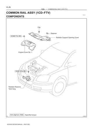
  • 1. 11–76 FUEL – COMMON RAIL ASSY (1CD–FTV) COMMON RAIL ASSY (1CD–FTV) 110UB–01 COMPONENTS Clip Ratainer 8.0 (82, 71 in.Vlbf) Radiator Support Opening Cover Engine Cover No. 1 6.0 (61, 53 in.Vlbf) Radiator Reserve Tank Assy N·m (kgf·cm, ft·lbf) : Specified torque A79437 AVENSIS REPAIR MANUAL (RM1018E)
  • 2. 11–77 FUEL – COMMON RAIL ASSY (1CD–FTV) * 31 (316, 23) 34 (347, 25) 5.0 (51, 44 in.Vlbf) Injection Pipe Clamp No. 2 z Injection Pipe Sub–assy z Fuel Inlet Pipe Sub–assy * 31 (316, 23) 34 (347, 25) * 31 (316, 23) 34 (347, 25) Intake Manifold Insulator No. 1 Common Rail Assy 5.0 (51, 44 in.Vlbf) 43 (438, 32) Fuel Hose No. 4 N·m (kgf·cm, ft·lbf) : Specified torque z Non–reusable part * Use SST A79438 AVENSIS REPAIR MANUAL (RM1018E)
  • 3. 11–78 FUEL – COMMON RAIL ASSY (1CD–FTV) 110UC–01 REPLACEMENT 1. DRAIN ENGINE COOLANT (See page 16–44) 2. REMOVE RADIATOR SUPPORT OPENING COVER 3. REMOVE ENGINE COVER NO.1 (a) Remove the 5 nuts and the engine cover. 4. REMOVE RADIATOR RESERVE TANK ASSY (See page 16–50) 5. REMOVE FUEL INLET PIPE SUB–ASSY NOTICE: After removing the fuel inlet pipe, cover the common rail and the injection pump with vinyl tape to prevent dust from being introduced. (a) Using SST, remove the fuel inlet pipe from the common SST rail. SST 09023–12700 A79148 (b) Using SST, remove the fuel inlet pipe from the injection pump. SST 09023–12700 6. REMOVE INJECTION PIPE SUB–ASSY NO.1 (a) Remove the 2 nuts and the 2 upper infection pipe clamps from the intake manifold. (b) Using SST, remove the injection pipe from the common rail side. SST 09023–12700 SST (c) Using SST, remove the injection pipe from the injector side. A79143 SST 09023–12700 (d) After removing the fuel pipe, to prevent dust or foreign ob- jects from being introduced, cover the common rail with vinyl tape and protect the injector inlet with a vinyl or plas- tic bag. 7. REMOVE INJECTION PIPE SUB–ASSY NO.2 SST 09023–12700 HINT: Perform the same procedures as injection pipe No. 1. 8. REMOVE INJECTION PIPE SUB–ASSY NO.3 SST 09023–12700 HINT: Perform the same procedures as injection pipe No. 1. AVENSIS REPAIR MANUAL (RM1018E)
  • 4. 11–79 FUEL – COMMON RAIL ASSY (1CD–FTV) 9. REMOVE INJECTION PIPE SUB–ASSY NO.4 SST 09023–12700 HINT: Perform the same procedures as injection pipe No. 1. 10. DISCONNECT FUEL HOSE NO.4 (a) Disconnect the fuel hose from the common rail. 11. REMOVE INTAKE MANIFOLD INSULATOR NO.1 (See page 11–69) 12. REMOVE COMMON RAIL ASSY (a) Disconnect the engine wire connector from the bracket. (b) Remove the 2 bolts and the common rail. A79154 13. INSTALL COMMON RAIL ASSY Torque: 43 NVm (438 kgfVcm, 32 ftVlbf) 14. INSTALL INTAKE MANIFOLD INSULATOR NO.1 (See page 11–69) 15. INSTALL INJECTION PIPE SUB–ASSY NO.1 30 cm NOTICE: (11.81 in.) S In case of having the common rail replaced, must re- place the injection pipes, too. S When assembling the pipes, perform the operation SST with the engine cold under room temperature. (a) Remove the vinyl or the plastic bag from the injector and vinyl tape from the common rail. A79147 (b) Temporarily install the injection pipe. AVENSIS REPAIR MANUAL (RM1018E)
  • 5. 11–80 FUEL – COMMON RAIL ASSY (1CD–FTV) (c) Using SST, tighten the nut of the injection pipe to the com- mon rail side. SST 09023–12700 Torque: 42 NVm (428 kgfVcm, 31 ftVlbf) for a used pipe using SST 46 NVm (469 kgfVcm, 34 ftVlbf) for a used pipe not using SST 31 NVm (316 kgfVcm, 23 ftVlbf) for a new pipe using SST 34 NVm (347 kgfVcm, 25 ftVlbf) for a new pipe not using SST HINT: S Use a torque wrench with a fulcrum length of 30 cm (11.81 in.) S Check if the used pipe has deflection or is installed prop- erly after injection pipe is reassembled. If there is deflec- tion or if it can not be installed properly, replace the used pipe with a new pipe. (d) Using SST, tighten the nut of the injection pipe to the injec- tor side. SST 09023–12700 Torque: 42 NVm (428 kgfVcm, 31 ftVlbf) for a used pipe using SST 46 NVm (469 kgfVcm, 34 ftVlbf) for a used pipe not using SST 31 NVm (316 kgfVcm, 23 ftVlbf) for a new pipe using SST 34 NVm (347 kgfVcm, 25 ftVlbf) for a new pipe not using SST HINT: S Use a torque wrench with a fulcrum length of 30 cm (11.81 in.) S Check if the used pipe has deflection or is installed prop- erly after injection pipe is reassembled. If there is deflec- tion or if it can not be installed properly, replace the used pipe with a new pipe. (e) Install the 2 upper injection pipe clamps with the 2 nuts. Torque: 5.0 NVm (51 kgfVcm, 44 in.Vlbf) 16. INSTALL INJECTION PIPE SUB–ASSY NO.2 SST 09023–12700 HINT: Perform the same procedures as injection pipe No. 1. 17. INSTALL INJECTION PIPE SUB–ASSY NO.3 SST 09023–12700 HINT: Perform the same procedures as injection pipe No. 1. 18. INSTALL INJECTION PIPE SUB–ASSY NO.4 SST 09023–12700 HINT: Perform the same procedures as injection pipe No. 1. AVENSIS REPAIR MANUAL (RM1018E)
  • 6. 11–81 FUEL – COMMON RAIL ASSY (1CD–FTV) 19. INSTALL FUEL INLET PIPE SUB–ASSY 30 cm NOTICE: (11.81 in.) S In case of having the common rail replaced, must re- place fuel inlet pipe, too. S When assembling the pipe, perform the operation SST with the engine cold under room temperature. (a) Temporarily install the fuel inlet pipe. (b) Using SST, tighten the nut of the fuel inlet pipe to the com- A79149 mon rail side. SST 09023–12700 Torque: 42 NVm (428 kgfVcm, 31 ftVlbf) for a used pipe using SST 46 NVm (469 kgfVcm, 34 ftVlbf) for a used pipe not using SST 31 NVm (316 kgfVcm, 23 ftVlbf) for a new pipe using SST 34 NVm (347 kgfVcm, 25 ftVlbf) for a new pipe not using SST HINT: S Use a torque wrench with a fulcrum length of 30 cm (11.81 in.) S Check if the used pipe has deflection or is installed prop- erly after inlet pipe is reassembled. If there is deflection or if it can not be installed properly, replace the used pipe with a new pipe. (c) Using SST, tighten the nut of the fuel inlet pipe to the injec- tion pump side. SST 09023–12700 Torque: 42 NVm (428 kgfVcm, 31 ftVlbf) for a used pipe using SST 46 NVm (469 kgfVcm, 34 ftVlbf) for a used pipe not using SST 31 NVm (316 kgfVcm, 23 ftVlbf) for a new pipe using SST 34 NVm (347 kgfVcm, 25 ftVlbf) for a new pipe not using SST HINT: S Use a torque wrench with a fulcrum length of 30 cm (11.81 in.) S Check if the used pipe has deflection or is installed prop- erly after inlet pipe is reassembled. If there is deflection or if it can not be installed properly, replace the used pipe with a new pipe. 20. INSTALL RADIATOR RESERVE TANK ASSY (See page 16–50) 21. INSTALL ENGINE COVER NO.1 Torque: 8.0 NVm (82 kgfVcm, 71 in.Vlbf) 22. ADD ENGINE COOLANT (See page 16–44) 23. CHECK FOR ENGINE COOLANT LEAKS (See page 16–37) 24. CHECK FOR FUEL LEAKS (See page 11–60) AVENSIS REPAIR MANUAL (RM1018E)
  • 7. 11–82 FUEL – FUEL FILTER ASSY (1CD–FTV) FUEL FILTER ASSY (1CD–FTV) 110UD–01 REPLACEMENT 1. REMOVE AIR CLEANER ASSY (a) Disconnect the connector. (b) Remove the air cleaner cap with the air cleaner hose. (c) Remove the air cleaner filter element. (d) Remove the 3 bolts and the air cleaner case. 2. REMOVE FUEL FILTER ASSY (a) Disconnect the 2 fuel hose from the fuel filter. (STD or COLD) (b) Disconnect the 3 fuel hose from the fuel filter. (W/ ADDTIONAL HEATER) (c) Disconnect the 2 connectors. (d) Remove the 2 bolts and the fuel filter. 3. DRAIN FUEL (a) Loosen the drain plug, and drain the fuel from the fuel filter. 4. REMOVE LEVEL WARNING SWITCH (a) Clamp the fuel filter in a soft jaw vise. (b) Using pliers, remove the level warning switch. NOTICE: Be careful not to damage the level warning switch. A79188 5. REMOVE FUEL FILTER ELEMENT (a) Using SST, remove the fuel filter element. SST 09228–64030 SST A80091 6. INSTALL FUEL FILTER ELEMENT (a) Check and clean the fuel filter installation surface. (b) Apply fuel to a gasket of a new fuel filter element. (c) Lightly screw the fuel filter element into place, and tighten it until the gasket comes into contact with the seat. (d) Tighten it additional 3/4 turn by hand. A79190 AVENSIS REPAIR MANUAL (RM1018E)
  • 8. 11–83 FUEL – FUEL FILTER ASSY (1CD–FTV) 7. INSTALL LEVEL WARNING SWITCH (a) Install a new O–ring to the level warning switch. (b) Apply fuel to the O–ring of the level warning switch. (c) Install the level warning switch to the fuel filter by hand. 8. INSTALL FUEL FILTER ASSY Torque: 18 NVm (178 kgfVcm, 13 ftVlbf) 9. INSTALL AIR CLEANER ASSY Torque: 7.0 NVm (71 kgfVcm, 62 in.Vlbf) 10. CHECK FOR FUEL LEAKS (See page 11–60) AVENSIS REPAIR MANUAL (RM1018E)
  • 9. 11–24 FUEL – FUEL INJECTOR ASSY (1AZ–FE) FUEL INJECTOR ASSY (1AZ–FE) 110U0–01 COMPONENTS 7.0 (71, 62 in.Vlbf) Engine Cover Sub–assy No. 1 Fuel Vapor Feed Hose VSV Connector Mass Air Flow Meter Connector Air Cleaner Cap Sub–assy Fuel Vapor Feed Hose No. 2 N·m (kgf·cm, ft·lbf) : Specified torque A79730 AVENSIS REPAIR MANUAL (RM1018E)
  • 10. 11–25 FUEL – FUEL INJECTOR ASSY (1AZ–FE) z Fuel Injector O–ring Fuel Injector Connector Fuel Injector Assy 20 (204, 15) Fuel Delivery Pipe Sub–assy EFI Fuel Pipe Clamp Delivery Pipe No. 1 Spacer Fuel Tube Sub–assy z Injector Vibration Insulator Ventilation Hose No. 2 N·m (kgf·cm, ft·lbf) : Specified torque z Non–reusable part A77907 AVENSIS REPAIR MANUAL (RM1018E)
  • 11. 11–26 FUEL – FUEL INJECTOR ASSY (1AZ–FE) 110U1–01 REPLACEMENT 1. DISCHARGE FUEL SYSTEM PRESSURE (See page 11–15) 2. REMOVE ENGINE COVER SUB–ASSY NO.1 (See page 10–26) 3. REMOVE AIR CLEANER CAP SUB–ASSY (See page 10–26) 4. DISCONNECT FUEL TUBE SUB–ASSY (a) Remove the fuel pipe clamp. Retainer (b) Using SST, disconnect the fuel tube. (at 4 places) SST 09268–21010 Fuel Pipe (1) Assemble SST to the connection of the fuel tube as Clamp shown in the illustration. (2) Turn SST, align the retainers inside the connector with SST into the connector. (3) Push in the SST and the connector together to- Turn wards the fuel tube assembly. NOTICE: SST S Check if there is any dirt or mud on the pipe and around the connector before disconnecting them and remove the dirt as necessary. Insert S Do not bent and twist the nylon tube. S When the connector and pipe are stuck, push and pull the connector to free. Pull the connector out carefully. S Prevent the disconnected pipe and connector from A77908 being damaged and foreign objects from being introduced, cover with a vinyl or plastic bag. O–ring Retainer Pipe Nylon Tube Housing A76220 5. REMOVE FUEL DELIVERY PIPE SUB–ASSY (a) Disconnect the ventilation hose. A77909 AVENSIS REPAIR MANUAL (RM1018E)
  • 12. 11–27 FUEL – FUEL INJECTOR ASSY (1AZ–FE) (b) Remove the 2 wire harness clamps. (c) Disconnect the 4 fuel injector connectors. (b) (c) (c) (b) (c) (c) A77910 (d) Remove the 2 bolts, and then remove the fuel delivery pipe together with the 4 fuel injectors. NOTICE: Be careful not to drop the fuel injectors when removing the delivery pipe. A78437 Delivery Pipe (e) Remove the 2 delivery pipe No. 1 spacers and the 4 insu- No. 1 Spacer lators from the cylinder head. Insulator A77911 6. REMOVE FUEL INJECTOR ASSY (a) Pull out the 4 fuel injectors. A77912 7. INSTALL FUEL INJECTOR ASSY (a) Apply a light coat of spindle oil or gasoline to new O–rings and install them to each fuel injector. New O–ring A78481 AVENSIS REPAIR MANUAL (RM1018E)
  • 13. 11–28 FUEL – FUEL INJECTOR ASSY (1AZ–FE) (b) Apply a light coat of spindle oil or gasoline on the place Turn where a fuel delivery pipe contacts the O–ring. Push (c) Push the fuel injector while twisting it back and forth to install it to the fuel delivery pipe. NOTICE: S Be careful not to twist the O–ring. S After installing the fuel injectors, check that they turn smoothly. If not, reinstall it with a new O–ring. A77913 8. INSTALL FUEL DELIVERY PIPE SUB–ASSY (a) Install 4 new insulators and the 2 delivery pipe No. 1 spacers to the cylinder head. (b) Place the fuel delivery pipe and the 4 fuel injectors togeth- er to the cylinder head. Turn NOTICE: Be careful not to drop the fuel injectors when installing the fuel delivery pipe. A77914 (c) Temporarily install 2 bolts which are used to secure the fuel delivery pipe to the cylinder head. (d) Check that the fuel injectors rotate smoothly. If the fuel injectors do not rotate smoothly, the probable cause is incorrect installation of O–ring. Replace with the O–ring. (e) Tighten the 2 bolts. Torque: 20 NVm (204 kgfVcm, 15 ftVlbf) (f) Connect the 4 fuel injector connectors. (g) Install the 2 wire harness clamps. (h) Connect the ventilation hose. Fuel Pipe 9. CONNECT FUEL TUBE SUB–ASSY Clamp (a) Push in the connector to the pipe until it makes ”click” sound. NOTICE: S Check if there is any damage or foreign objects on the connected part. S After connecting, check if the connector and the pipe Push are securely connected by pulling on them. A81621 (b) Install the fuel pipe clamp. 10. INSTALL AIR CLEANER CAP SUB–ASSY 11. CHECK FOR FUEL LEAKS (See page 11–19) 12. INSTALL ENGINE COVER SUB–ASSY NO.1 (See page 10–26) AVENSIS REPAIR MANUAL (RM1018E)
  • 14. 11–37 FUEL – FUEL INJECTOR ASSY (1AZ–FSE) FUEL INJECTOR ASSY (1AZ–FSE) 110TC–01 COMPONENTS x2 Clip Engine Room Cover Side x4 Clip Retainer Radiator Support Opening Cover 7.0 (71, 62 in.Vlbf) Engine Cover Sub–assy No. 1 Fuel Vapor Feed Hose VSV 1.5 (15, 13 in.Vlbf) Connector Mass Air Flow Meter Connector Air Cleaner Cap Sub–assy N·m (kgf·cm, ft·lbf) : Specified torque A78507 AVENSIS REPAIR MANUAL (RM1018E)
  • 15. 11–38 FUEL – FUEL INJECTOR ASSY (1AZ–FSE) Throttle Motor Connector Throttle Body Assy x4 9.0 (90, 80 in.Vlbf) z Throttle Body Gasket Water By–pass Hose No. 1 Water By–pass Hose No. 2 x4 Throttle Body Bracket 21 (210, 15) Ground Terminal 8.4 (86, 74 in.Vlbf) Wire Harness Protector 8.4 (86, 74 in.Vlbf) N·m (kgf·cm, ft·lbf) : Specified torque z Non–reusable part A78508 AVENSIS REPAIR MANUAL (RM1018E)
  • 16. 11–39 FUEL – FUEL INJECTOR ASSY (1AZ–FSE) Fuel Tube Sub–assy z Gasket Fuel Pipe Clamp z Gasket 25 (255, 18) 33 (331, 24) Fuel Pressure Pulsation z Fuel Pump Fuel Pump Assy Damper Assy Insulator 30 (306, 22) Fuel Pipe Sub–assy No. 1 9.0 (92, 80 in.Vlbf) Fuel Hose z Fuel Injector Back–up Ring No. 1 z Fuel Injector Back–up Ring No. 2 z O–ring z Fuel Injector Back–up Ring No. 3 38 (388, 28 ) Engine Cover Bracket N·m (kgf·cm, ft·lbf) : Specified torque z Non–reusable part A79577 AVENSIS REPAIR MANUAL (RM1018E)
  • 17. 11–40 FUEL – FUEL INJECTOR ASSY (1AZ–FSE) 30 (306, 22) Union to Connector Tube Hose 30 (306, 22) Vacuum Hose Intake Manifold Intake Manifold Insulator No. 1 x2 30 (306, 22) z Gasket Intake Air Control Valve Assy z Gasket 9.5 (97, 84 in.Vlbf) 9.8 (100, 7) Intake Manifold Insulator No. 2 21 (210, 15) Surge Tank Stay No. 1 38 (388, 28) Engine Cover Bracket Charcoal Canister Assy N·m (kgf·cm, ft·lbf) : Specified torque z Non–reusable part A79597 AVENSIS REPAIR MANUAL (RM1018E)
  • 18. 11–41 FUEL – FUEL INJECTOR ASSY (1AZ–FSE) z E–ring z O–ring z Fuel Injector Back–up Ring No. 1 z Fuel Injector Back–up Ring No. 3 z Fuel Injector Back–up Ring No. 2 z Gasket Injector Assy z Fuel Injector Seal 13 (127, 9) Fuel Delivery Pipe Sub–assy Nozzle Holder Clamp x5 19 (194, 14) N·m (kgf·cm, ft·lbf) : Specified torque z Non–reusable part A79598 AVENSIS REPAIR MANUAL (RM1018E)
  • 19. 11–10 FUEL – FUEL INJECTOR ASSY (1ZZ–FE/3ZZ–FE) FUEL INJECTOR ASSY (1ZZ–FE/3ZZ–FE) 110TY–01 COMPONENTS 1ZZ–FE: z Fuel Injector O–Ring Fuel Injector Assy 3ZZ–FE: z Fuel Injector O–Ring Clip z Fuel Injector Grommet 7.0 (71, 62 in.·lbf) Fuel Injector Assy 19 (189, 14) Cylinder Head Cover No. 2 Fuel Pipe Clamp No. 2 Fuel Delivery Pipe Sub–assy Fuel Tube Sub–assy z Injector Vibration Insulator 9.0 (91, 80 in.·lbf) No. 1 Spacer Ventilation Hose Fuel Injector Connector N·m (kgf·cm, ft·lbf) : Specified torque z Non–reusable part A78470 AVENSIS REPAIR MANUAL (RM1018E)
  • 20. 11–11 FUEL – FUEL INJECTOR ASSY (1ZZ–FE/3ZZ–FE) 110TZ–01 REPLACEMENT 1. DISCHARGE FUEL SYSTEM PRESSURE (See page 11–1) 2. REMOVE CYLINDER HEAD COVER NO.2 (See page 10–9) 3. SEPARATE FUEL TUBE SUB–ASSY (a) Remove the fuel pipe clamp. Retainer (b) Using SST, disconnect the fuel tube. (at 4 places) SST 09268–21010 (1) Assemble SST to the connection of the fuel tube as Fuel Pipe shown in the illustration. Clamp (2) Turn SST, align the retainers inside the connector with SST into the connector. (3) Push in the SST and the connector together to- Turn wards the fuel tube assembly. SST NOTICE: S Check if there is any dirt or mud on the pipe and around the connector before disconnecting them and remove the dirt as necessary. Insert S Do not bent and twist the nylon tube. S When the connector and pipe are stuck, push and pull the connector to free. Pull the connector out carefully. S Prevent the disconnected pipe and connector from A78471 being damaged and foreign objects from being introduced, cover with a vinyl or plastic bag. O–ring Retainer Pipe Nylon Tube Housing A76220 4. REMOVE FUEL DELIVERY PIPE SUB–ASSY (a) Disconnect the ventilation hose. A78472 AVENSIS REPAIR MANUAL (RM1018E)
  • 21. 11–12 FUEL – FUEL INJECTOR ASSY (1ZZ–FE/3ZZ–FE) (b) Disconnect the 4 fuel injector connectors. (a) (c) Remove the 3 wire harness clamps. (a) (a) (a) (b) (b) (b) A78473 (d) Remove the 3 bolts, and then remove the fuel delivery pipe together with the 4 fuel injectors. NOTICE: Be careful not to drop the fuel injectors when removing the fuel delivery pipe. A78480 (e) Remove the 2 delivery pipe No. 1 spacers and the 4 insu- Delivery Pipe No. 1 spacer lators from the cylinder head. Insulator A78475 5. REMOVE FUEL INJECTOR ASSY (a) Pull out the 4 fuel injectors from the fuel delivery pipe. A78476 AVENSIS REPAIR MANUAL (RM1018E)
  • 22. 11–13 FUEL – FUEL INJECTOR ASSY (1ZZ–FE/3ZZ–FE) 1ZZ–FE: 6. INSTALL FUEL INJECTOR ASSY (a) Install new grommets to each fuel injector. (3ZZ–FE) (b) Apply a light coat of spindle oil or gasoline to new O–rings, and install them to each fuel injector. New O–ring A78477 3ZZ–FE: New O–ring New Grommet A78478 (c) Apply a light coat of spindle oil or gasoline on the place where the fuel delivery pipe contacts the O–ring. (d) Push the fuel injector while twisting it back and forth to Turn install it to the fuel delivery pipe. Push NOTICE: S Be careful not to twist the O–ring. S After installing the fuel injectors, check that they turn smoothly. If not, reinstall it with a new O–ring. A78479 7. INSTALL FUEL DELIVERY PIPE SUB–ASSY A (a) Instal 4 new insulators and the 2 delivery pipe No. 1 spacers to the cylinder head. A (b) Place the fuel delivery pipe and 4 fuel injectors together to the cylinder head. Turn NOTICE: Be careful not to drop the fuel injectors when installing the B fuel delivery pipe. A78474 (c) Temporarily install 3 bolts which are used to secure the fuel delivery pipe to the cylinder head. (d) Check that the fuel injectors rotate smoothly. If fuel injectors do not rotate smoothly, the probable cause is in- correct installation of O–ring. Replace with the O–ring. (e) Tighten the 3 bolts. Torque: 19 NVm (194 kgfVcm, 14 ftVlbf) for bolt A 9.0 NVm (92 kgfVcm, 80 in.Vlbf) for bolt B (f) Install the 3 wire harness clamps. (g) Connect the 4 fuel injector connectors. (h) Connect the ventilation hose. AVENSIS REPAIR MANUAL (RM1018E)
  • 23. 11–14 FUEL – FUEL INJECTOR ASSY (1ZZ–FE/3ZZ–FE) 8. CONNECT FUEL TUBE SUB–ASSY Fuel Pipe (a) Push in the connector to the pipe until it makes ”click” Clamp sound. Push NOTICE: S Check if there is any damage or foreign objects on the connected part. S After connecting, check if the connector and the pipe are securely connected by pulling on them. A81613 (b) Install the fuel pipe clamp. 9. CHECK FOR FUEL LEAKS (See page 11–5) 10. INSTALL CYLINDER HEAD COVER NO.2 (See page 10–9) AVENSIS REPAIR MANUAL (RM1018E)
  • 24. FUEL – FUEL PRESSURE PULSATION DAMPER 11–29 ASSY (1AZ–FE) FUEL PRESSURE PULSATION DAMPER ASSY (1AZ–FE) 110U2–01 REPLACEMENT 1. DISCHARGE FUEL SYSTEM PRESSURE (See page 11–15) 2. REMOVE ENGINE COVER SUB–ASSY NO.1 (See page 10–26) 3. REMOVE AIR CLEANER CAP SUB–ASSY (See page 10–26) 4. DISCONNECT FUEL TUBE SUB–ASSY (See page 11–26) SST 09268–21010 5. REMOVE FUEL PRESSURE PULSATION DAMPER ASSY (a) Remove the 2 bolts, and then remove the fuel pressure pulsation damper. A77915 6. INSTALL FUEL PRESSURE PULSATION DAMPER ASSY (a) Apply a light coat of spindle oil or gasoline to a new O–ring, and install it to the fuel pressure pulsation damper. (b) Install the fuel pressure pulsation damper with the 2 bolts. Torque: 9.0 NVm (92 kgfVcm, 80 in.Vlbf) 7. CONNECT FUEL TUBE SUB–ASSY (See page 11–26) 8. INSTALL AIR CLEANER CAP SUB–ASSY 9. CHECK FOR FUEL LEAKS (See page 11–19) 10. INSTALL ENGINE COVER SUB–ASSY NO.1 (See page 10–26) AVENSIS REPAIR MANUAL (RM1018E)
  • 25. 11–49 FUEL – FUEL PUMP ASSY (1AZ–FSE) FUEL PUMP ASSY (1AZ–FSE) 110TA–01 COMPONENTS x2 Clip Engine Room Cover Side x4 Clip Retainer Radiator Support Opening Cover 7.0 (71, 62 in.Vlbf) Engine Cover Sub–assy No. 1 Fuel Vapor Feed Hose VSV 1.5 (15, 13 in.Vlbf) Connector Mass Air Flow Meter Connector Air Cleaner Cap Sub–assy N·m (kgf·cm, ft·lbf) : Specified torque A78507 AVENSIS REPAIR MANUAL (RM1018E)
  • 26. 11–50 FUEL – FUEL PUMP ASSY (1AZ–FSE) Throttle Motor Connector Throttle Body Assy x4 9.0 (90, 80 in.Vlbf) z Throttle Body Gasket Water By–pass Hose No. 1 Water By–pass Hose No. 2 x4 Throttle Body Bracket 21 (210, 15) Ground Terminal 8.4 (86, 74 in.Vlbf) Wire Harness Protector 8.4 (86, 74 in.Vlbf) N·m (kgf·cm, ft·lbf) : Specified torque z Non–reusable part A78508 AVENSIS REPAIR MANUAL (RM1018E)
  • 27. 11–51 FUEL – FUEL PUMP ASSY (1AZ–FSE) Fuel Tube Sub–assy z Gasket Fuel Pipe Clamp z Gasket 25 (255, 18) 33 (331, 24) Fuel Pressure Pulsation z Fuel Pump Fuel Pump Assy Damper Assy Insulator 30 (306, 22) Fuel pipe Sub–assy No. 1 9.0 (92, 80 in.Vlbf) Fuel Hose z Fuel Injector Back–up Ring No. 1 z Fuel Injector Back–up Ring No. 2 z O–ring z Fuel Injector Back–up Ring No. 3 38 (388, 28 ) Engine Cover Bracket N·m (kgf·cm, ft·lbf) : Specified torque z Non–reusable part A79577 AVENSIS REPAIR MANUAL (RM1018E)
  • 28. 11–52 FUEL – FUEL PUMP ASSY (1AZ–FSE) 110TB–01 REPLACEMENT 1. DISCHARGE FUEL SYSTEM PRESSURE (See page 11–30) 2. REMOVE RADIATOR SUPPORT OPENING COVER (See page 18–16) 3. REMOVE ENGINE COVER SUB–ASSY NO.1 (See page 10–44) 4. REMOVE AIR CLEANER CAP SUB–ASSY (See page 10–44) 5. REMOVE ENGINE COVER BRACKET (a) Remove the bolt and the engine cover bracket. A79569 6. REMOVE FUEL PRESSURE PULSATION DAMPER SST ASSY (a) Disconnect the fuel tube sub–assy. (See page 11–30) (b) Using SST, remove the fuel pressure pulsation damper assy, the fuel tube sub–assy and the 2 gasket. SST 09617–24011 A79570 7. REMOVE FUEL PIPE SUB–ASSY NO.1 (a) Remove the fuel hose. A79571 (b) Clamp the union bolt on the fuel pump assy with a 21 mm wrench and remove the fuel pipe sub–assy No. 1 from the fuel pump assy using a 19 mm union–nut wrench. NOTICE: Do not loosen the union bolt on the fuel pump assy. If it be- come loose, replace the fuel pump assy with new fuel pump assy. A79572 AVENSIS REPAIR MANUAL (RM1018E)
  • 29. 11–53 FUEL – FUEL PUMP ASSY (1AZ–FSE) (c) Remove the 2 bolts first, then remove the fuel pipe sub– assy No. 1 from the fuel delivery pipe sub–assy. NOTICE: Be careful not to damage both the sealing surfaces of the fuel delivery pipe and the fuel pump when removing the fuel pipe No.1. A79573 8. REMOVE FUEL PUMP ASSY (a) Disconnect the fuel pump assy connector. (b) Remove the 2 nuts and the fuel pump assy. (c) Remove the fuel pump insulator. A79574 9. INSTALL FUEL PUMP ASSY (a) Turn the crankshaft and set the camshaft to the position where the oil port of the camshaft can be seen from the fuel pump mounting hole. (b) From the fuel pump mounting hole of the cylinder head, pour 35 to 45cc (2.14 to 2.75 cu in) engine oil into the cyl- inder head. (c) For more smooth rotation, apply engine oil on the cam A79834 lobe which can be seen from the fuel pump mounting hole using fingers. (d) Set a new fuel pump insulator and fuel pump assy with the 2 nuts. Torque: 25 NVm (255 kgfVcm, 18 ftVlbf) AVENSIS REPAIR MANUAL (RM1018E)
  • 30. 11–54 FUEL – FUEL PUMP ASSY (1AZ–FSE) 10. INSTALL FUEL PIPE SUB–ASSY NO.1 (a) Attach a new O–ring, fuel injector back–up ring No. 1, No. 2 and No. 3 to the fuel pipe sub–assy No.1. (b) Apply a small amount of fuel on the O–ring and install the fuel pipe sub–assy No. 1 to the fuel pump assy and the fuel delivery pipe sub–assy. NOTICE: Be careful not to damage both the sealing surfaces of the fuel delivery pipe and the fuel pump when installing the fuel pipe No.1. (c) Tighten the nut by hand to attach the fuel pipe sub–assy Fuel Injector No. 1 to the fuel pump assy. Back–up Ring No. 1 (d) In order to secure the fuel pipe sub–assy No. 1 to the fuel Fuel Injector delivery pipe sub–assy, tighten the 2 bolts to the specified Back–up Ring No. 2 torque. Torque: 9.0 NVm (92 kgfVcm, 80 in.Vlbf) O–ring (e) Clamp the union bolt on the fuel pump assy with a 21 mm Fuel injector wrench and tighten the nut with the specified torque to se- Back–up Ring No. 3 A79575 cure the fuel pipe sub–assy No. 1 to the fuel pump assy using a 19 mm union–nut wrench. Torque: 30 NVm (306 kgfVcm, 22 ftVlbf) 11. INSTALL FUEL PRESSURE PULSATION DAMPER ASSY (a) Install the fuel pulsation damper assy to the fuel pump assy after fitting new 2 gaskets and fuel tube sub–assy between those assys. A79576 (b) Using SST, install the fuel pressure pulsation damper SST assy to the fuel pump assy. SST 09617–24011 Torque: 33 NVm (331 kgfVcm, 24 ftVlbf) (c) Connect the fuel tube sub–assy. A79570 AVENSIS REPAIR MANUAL (RM1018E)
  • 31. 11–55 FUEL – FUEL PUMP ASSY (1AZ–FSE) 12. INSTALL ENGINE COVER BRACKET (a) Install the engine cover bracket with the bolt. Torque: 38 NVm (388 kgfVcm, 28 ftVlbf) 13. INSTALL AIR CLEANER CAP SUB–ASSY (See page 10–44) 14. CHECK FOR FUEL LEAKS 15. INSTALL ENGINE COVER SUB–ASSY NO.1 Torque: 7.0 NVm (71 kgfVcm, 62 in.Vlbf) 16. INSTALL RADIATOR SUPPORT OPENING COVER AVENSIS REPAIR MANUAL (RM1018E)
  • 32. 11–84 FUEL – FUEL PUMP ASSY (GASOLINE) FUEL PUMP ASSY (GASOLINE) 110U3–01 COMPONENTS Seat Fixed Type: Rear Seat Cushion Assembly x4 Rear Floor Service Hole Cover 1AZ–FSE: Fuel Pump Connector Fuel Tank Return Tube Fuel Tank Main Tube Sub–assy Fuel Evaporation Tube z Fuel Pump Gauge Retainer Sub–assy No. 2 Tube Joint Clip Fuel Suction w/ Pump & Gage Tube Assy z Fuel Suction Tube Set Gasket N·m (kgf·cm, ft·lbf) : Specified torque z Non–reusable part A78441 AVENSIS REPAIR MANUAL (RM1018E)
  • 33. 11–85 FUEL – FUEL PUMP ASSY (GASOLINE) 110U4–01 REPLACEMENT 1. DISCHARGE FUEL SYSTEM PRESSURE HINT: S 1ZZ–FE/3ZZ–FE: 11–1 S 1AZ–FE: 11–15 S 1AZ–FSE: 11–30 2. REMOVE REAR SEAT CUSHION ASSY (SEAT FIXED TYPE) (See page 72–32) (a) 3. REMOVE REAR FLOOR SERVICE HOLE COVER (a) Remove the 4 screws, and then remove the rear floor ser- vice hole cover. (b) Disconnect the fuel pump connector. A78442 Tube Joint Clip 4. DISCONNECT FUEL TANK RETURN TUBE (1AZ–FSE 1 ENGINE TYPE) 2 (a) Remove the tube joint clip, and pull out the fuel return tube. NOTICE: S Check if there is any dirt or mud around the connector before this operation and remove the dirt as neces- sary. A78443 S Be careful of mud because the fuel tube joint has an O–ring which seals the pipe and connector that can be contaminated. Fuel Tube Joint Nylon Tube S Do not use any tool in this operation. S Do not bend or twist the nylon tube. Protect the con- nector by covering it with a vinyl or plastic bag. S When the pipe and connector are stuck, push and pull O–ring the connector to release and pull the connector out Tube Joint Clip carefully. Fuel Suction Plate A60575 AVENSIS REPAIR MANUAL (RM1018E)
  • 34. 11–86 FUEL – FUEL PUMP ASSY (GASOLINE) 5. DISCONNECT FUEL TANK MAIN TUBE SUB–ASSY (a) Pinch the tube connector and pull out the fuel tank main tube. 1 Pinch NOTICE: S Check if there is any dirt or mud around the connector before this operation and remove the dirt as neces- sary. 2 1 Pinch S Be careful of mud because the quick connector has A78444 an O–ring which seals the pipe and connector that can be contaminated. S Do not use any tool in this operation. Tube Connector S Do not bend or twist the nylon tube. Protect the con- Nylon Tube nector by covering it with a vinyl or plastic bag. S When the pipe and connector are stuck, push and pull the connector to release and pull the connector out carefully. O–ring Pipe A75650 6. DISCONNECT FUEL EVAPORATION TUBE SUB–ASSY NO.2 (a) Pinch the fuel tube connector clip and pull out the fuel evaporation tube. 1 Pinch NOTICE: S Check if there is any dirt or mud around the connector before this operation and remove the dirt as neces- 2 1 Pinch sary. A78445 S Be careful of mud because the quick connector has an O–ring which seals the pipe and connector that Fuel Tube can be contaminated. Connector Clip S Do not use any tool in this operation. Nylon Tube O–ring S Do not bend or twist the nylon tube. Protect the con- nector by covering it with a vinyl or plastic bag. S When the pipe and connector are stuck, push and pull the connector to release and pull the connector out Pipe carefully. Fuel Tube Connector A65059 7. REMOVE FUEL SUCTION W/PUMP & GAGE TUBE SST ASSY (a) Using SST, loosen the fuel pump gauge retainer. SST 09808–14010 NOTICE: Do not use other tools in this operation. Damage to the fuel pump gauge retainer and the fuel tank may result. Rib HINT: A78446 A rib on the fuel pump gauge retainer can be fitted into a tip of the SST. AVENSIS REPAIR MANUAL (RM1018E)
  • 35. 11–87 FUEL – FUEL PUMP ASSY (GASOLINE) (b) Remove the fuel pump gauge retainer. (c) Remove the fuel suction w/ pump & gage tube. NOTICE: Be careful that the arm of the fuel sender gage should not be bent. (d) Remove the gasket from the tank. A78447 8. INSTALL FUEL SUCTION W/PUMP & GAGE TUBE ASSY (a) Install a new gasket to the fuel tank. (b) Install the fuel suction w/ pump & gage tube. NOTICE: Be careful that the arm of the fuel sender gage should not Triangle Mark be bent. (c) Align the triangle mark of the fuel suction w/ pump & gage Matchmark A78448 tube with the matchmark location the fuel tank. (d) Temporarily install the fuel pump gauge retainer. SST (e) Using SST, tighten the fuel pump gauge retainer until the arrow mark is aligned with the center mark on the fuel tank. SST 09808–14010 NOTICE: Do not use other tools in this operation. Damage to the fuel Rib pump gauge retainer and the fuel tank may result. A78446 HINT: A rib on the fuel pump gauge retainer can be fitted into a tip of the SST. (f) Check that the arrow mark and center mark are aligned Arrow Mark as shown in the illustration. A78449 AVENSIS REPAIR MANUAL (RM1018E)
  • 36. 11–88 FUEL – FUEL PUMP ASSY (GASOLINE) 9. CONNECT FUEL EVAPORATION TUBE SUB–ASSY NO.2 (a) Push in the fuel tube connector to the pipe until it makes ”click” sound. NOTICE: S Check if there is any damage or foreign objects on the connected part. Push S After connecting, check if the fuel tube connector and A81614 the pipe are securely connected by pulling on them. 10. CONNECT FUEL TANK MAIN TUBE SUB–ASSY (a) Push in the fuel tube connector to the pipe until it makes ”click” sound. NOTICE: S Check if there is any damage or foreign objects on the connected part. Push S After connecting, check if the fuel tube connector and the pipe are securely connected by pulling on them. A81615 Tube Joint Clip 11. CONNECT FUEL TANK RETURN TUBE (1AZ–FSE 2 1 ENGINE TYPE) (a) Install in the fuel return tube with the tube joint clip. NOTICE: S Check that there is no scratch or foreign objects on Collar the connecting part. S Check that the fuel tube joint is inserted securely. S Check that the tube joint clip is on the collar of the fuel A81616 tube joint. S After installing the tube joint clip, check that the fuel tube joint has not been pulled off. 12. CHECK FOR FUEL LEAKS HINT: S 1ZZ–FE/3ZZ–FE: 11–5 S 1AZ–FE: 11–19 S 1AZ–FSE: 11–33 13. INSTALL REAR FLOOR SERVICE HOLE COVER 14. INSTALL REAR SEAT CUSHION ASSY (SEAT FIXED TYPE) (See page 72–32) AVENSIS REPAIR MANUAL (RM1018E)
  • 37. 11–22 FUEL – FUEL SYSTEM (1AZ–FE) 110UY–01 INSPECTION 1. INSPECT FUEL INJECTOR ASSY (a) Inspect injector resistance (1) Using an ohmmeter, measure the resistance be- tween the terminals. Resistance: 13.4 to 14.2 W at 20_C (68_F) If the resistance is not as specified, replace the injector. (b) Inspect injector inspection CAUTION: This test involves high–pressure fuel and electricity. Take every precaution regarding safe handling of both the fuel and the electricity. Preform this test in a safe area, and avoid any sparks or flame. Do not smoke. (1) Obtain new No. 1 fuel pipe (part No. 23901–0H040) Fuel Tube Connector and remove the fuel tube connector from the pipe. A50710 (2) Install the fuel tube connector to SST (hose), then Fuel Tube Connector connect the tube connector and the fuel pipe. SST 09268–41047 (95336–08070) SST CAUTION: (Hose) Connect the fuel tube connector (quick type) after observ- ing the precautions to prevent fuel from spraying. B12947 SST (Hose) (3) Install the O–ring to the injector. (4) Connect SST (union and hose) to the injector, and hold the injector and the union with SST (clamp) SST (Union) SST 09268–41047 (09268–41110, 09268–41300, O–Ring 95336–08070) SST (5) Put the injector into a graduated cylinder. (Clamp) CAUTION: Install a suitable vinyl tube onto the injector to contain gas- Vinyl Tube A51875 oline spray. (6) Operate the fuel pump.(See Page 11–19) AVENSIS REPAIR MANUAL (RM1018E)
  • 38. 11–23 FUEL – FUEL SYSTEM (1AZ–FE) (7) Connect SST (wire) to the injector and the battery for 15 seconds, and measure the injection volume with a graduated cylinder. Test each injector 2 or 3 times. SST 09842–30080 Injection volume: SST Injection volume Difference between each injector 60 to 73 cm3 (3.6 to 4.5 cu in.) 13 cm3 (0.9 cu in.) or less A50700 in 15 seconds NOTICE: Always do the switching at the battery side. If the injection volume is not as specified, replace the injector. (c) Inspect leakage (1) In the condition above, disconnect the test probes of SST (wire) from the battery and check the fuel leakage from the injector. Fuel drop: 1 drop or less in 12 minutes B00069 2. INSPECT FUEL PUMP (a) Insect fuel pump resistance. (1) Using an ohmmeter, measure the resistance be- tween the terminals. Resistance: 0.2 to 3.0 W at 20_C (68_F) (b) Inspect fuel pump operation (1) Apply battery voltage to both the terminals. Check that the pump operates. A16628 A32859 NOTICE: S These tests must be done quickly (within 10 seconds) to prevent damage to the pump. S Keep fuel pump as far away from the battery as pos- sible. S Always do the switching at the battery side. AVENSIS REPAIR MANUAL (RM1018E)
  • 39. 11–19 FUEL – FUEL SYSTEM (1AZ–FE) 110UX–01 ON–VEHICLE INSPECTION 1. CHECK FUEL PRESSURE Fuel Tube Connector (a) Discharge the pressure in the fuel system and take pre- cautions for possible fuel spillage.(See page 11–15) (b) Check that the battery voltage is above 12 V. (c) Disconnect the negative (–) battery cable. (d) Pull out the connecter from a new fuel tube. HINT: Part No. 23901–0H040 A50710 (e) Remove the fuel pipe clamp No.1 from the fuel tube con- nector. Fuel Pipe Clamp No.1 A60083 (f) Disconnect the fuel tube connector from the fuel pipe A while pinching part A with fingers as shown in the illustra- tion. CAUTION: S Do not disconnect the fuel tube connector (quick type) until after you have discharged the fuel system A pressure and taken appropriate steps to prevent fuel spillage. B12941 S There may be remained pressure in the fuel lines after discharging the pressure. Take precautions to prevent fuel from spraying on you or your clothing or inside the engine compart- ment. AVENSIS REPAIR MANUAL (RM1018E)
  • 40. 11–20 FUEL – FUEL SYSTEM (1AZ–FE) (g) Install SST (pressure gauge) and a fuel tube connector using SST as shown in the illustration. SST (Clip) SST 09268–41047(95336–08070),09268–45014 (09268–41250, 09268–41200, 09268–41220) SST SST (T joint) (h) Wipe up any gasoline. (i) Reconnect the negative (–) battery cable. No.1 Fuel Pipe (j) Connect the hand–hand tester to the DLC3. (k) Measure the fuel pressure. Fuel pressure: 304 to 343 kPa (3.1 to 3.5 kgf/cm2, 44 to 50 psi) If pressure is high, replace the fuel pressure regulator. If pressure is low, check the fuel hoses connections, the fuel pump, the fuel filter and the fuel pressure regulator. SST (l) Disconnect the hand–held tester from the DLC3. (Hose) (m) Start the engine. (n) Measure the fuel pressure at idle. Fuel pressure: Fuel Tube Connector 304 to 343 kPa (3.1 to 3.5 kgf/cm2, 44 to 50 psi) B12975 (o) Stop the engine. (p) Check that the fuel pressure remains as specified for 5 minutes after the engine has stopped. Fuel pressure:147 kPa (1.5 kgf/cm2, 21 psi) or more If pressure is not as specified, check the fuel pump, the pres- sure regulator and/or the injectors. (q) After checking the fuel pressure, disconnect the negative (–) battery cable and carefully remove SST and the fuel tube connector to prevent gasoline from splashing. (r) Reconnect the No. 1 fuel pipe (fuel tube connector). CAUTION: After taking the precautions, connect the fuel tube con- necter (quick type). 2. CHECK FUEL PUMP OPERATION AND FUEL LEAK (a) When using the hand–held tester (1) Connect the hand–held tester to the DLC3. (2) Turn the ignition switch ON and the hand–held tes- ter main switch ON. NOTICE: Do not start the engine. (3) Select the active test mode on the hand–held tester. (4) Perform the active test. Check that the fuel pump operates and check for fuel leaks. AVENSIS REPAIR MANUAL (RM1018E)
  • 41. 11–21 FUEL – FUEL SYSTEM (1AZ–FE) (b) When not using hand–held tester (1) Connect the positive (+) lead form the battery to ter- minal 4 of the connector and connect the negative (–) lead to terminal 5. Battery (2) Check that the pump operates. 4 5 A75342 AVENSIS REPAIR MANUAL (RM1018E)
  • 42. 11–15 FUEL – FUEL SYSTEM (1AZ–FE) FUEL SYSTEM (1AZ–FE) 110UW–01 PRECAUTION 1. PRECAUTION (a) Before working on fuel system, disconnect negative (–) battery cable. (b) Do not smoke or work near fire when handling the fuel system. (c) Keep gasoline away from rubber or leather parts. 2. DISCHARGE FUEL SYSTEM PRESSURE CAUTION: S Do not disconnect any part of the fuel system until you have discharged the fuel system pressure. S Even after discharging the fuel pressure, place a shop rag over fittings as you separate them to reduce risk of fuel spray on yourself or in the engine compart- ment. Fuel (a) Disconnect the fuel pump connector. Pump (b) Start the engine. After the engine has stopped, turn the Connector ignition switch OFF. (c) Disconnect the negative (–) battery cable. (d) Connect the fuel pump connector. 3. FUEL SYSTEM (a) When disconnecting the high fuel pressure line, a large amount of gasoline will spill out, so observe these proce- A75341 dures. (1) Discharge the pressure in the fuel system. (See step 2) (2) Disconnect the fuel pump tube. (See page 11–93) (3) Drain the fuel that remained inside the fuel pump tube. (4) Cover the disconnected fuel pump tubes with a vinyl or a plastic bag to prevent damage and dirt. (5) Place a tray under the vehicle or point of disconnec- tion to catch any fuel that may spill. Vinyl or Plastic Bag B00679 AVENSIS REPAIR MANUAL (RM1018E)
  • 43. 11–16 FUEL – FUEL SYSTEM (1AZ–FE) CORRECT (b) Observe the following precautions when removing and New O–ring installing fuel injectors. NOTICE: Never reuse the O–ring. Delivery Pipe (1) When installing a new O–ring to the injector, be careful not to damage the injector. WRONG (2) Coat the new O–ring with grease or gasoline before Injector installing. Never use engine oil, gear oil or brake oil. A51878 (c) Install the injector to the delivery pipe and cylinder head Delivery Pipe as shown in the illustration. Before installing the injector, O–ring be sure to apply grease or gasoline on the place where the delivery pipe contacts the O–ring of the injector. Grommet B09613 (d) Observe these precautions when disconnecting the fuel O–ring Retainer Pipe delivery pipe. HINT: The structure of the metallic connector is as shown in the il- lustration on the left. Nylon Tube Housing A50709 (1) Remove the fuel pipe clamp No.2. Fuel Pipe Clamp No.2 (2) Find the metallic connector of the fuel tube assem- bly, slide it towards the vehicle rear and hold it as it is. A75343 (3)Assemble SST to the connection of the fuel pipe as shown the illustration. SST 09268–21010 SST A60818 AVENSIS REPAIR MANUAL (RM1018E)