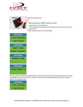
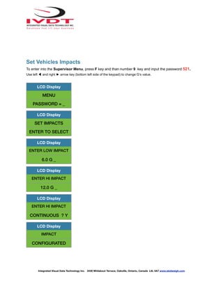
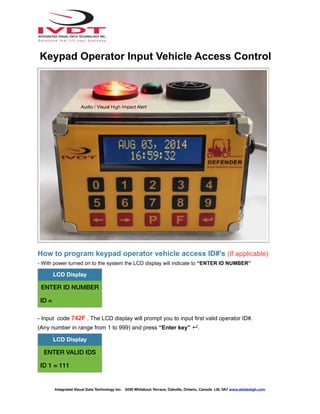
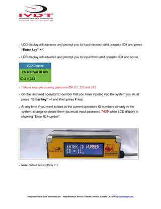
Integrated Visual Data Technology Inc. 3439 Whilabout Terrace, Oakville, Ontario, Canada L6L 0A7 www.skidweigh.com
IM Defender Series
IM V140
Installation, Calibration, Set Up & Operation Manual
General Installation Guide
This IM Defender V140 Series guide describes how to install, calibrate, set up and use your onboard systems.
Following the instructions in the ADMINISTRATION MENU you will be able to get the system set up, calibrate quickly.
In the event that you require additional assistance, please contact customer support via e-mail at
support@skidweigh.com , visit www.skidweigh.com or contact us at the address or contact number below:
Integrated Visual Data Technology Inc.
3439 Whilabout Terrace, Oakville, ON, Canada, L6L 0A7 Phone: 905-469-0985
Safety
Always disconnect the vehicle battery while installing SkidWeigh Plus / Defender system or any other electronic
product. Make sure that main electrical cable, pressure transducer and any other associated cables are securely
mounted and do not impede any of the vehicle’s controls. Use care when routing the components cables. Route the
cables where they will be protected. Use commonly accepted install practices for after market industrial vehicle
electronic devices. The installation of the systems should only be performed by an acknowledged lift truck dealer
technician or end user electro and hydraulic technical installer.
Here are two acceptable methods of making a wire connections:
* Soldering your connections (recommended)
* Crimp connectors (with the use of the proper crimping tool)
Regardless of the method you choose, ensure that the connection is mechanically sound and properly insulated. Use
high quality electrical tape and shrink tubing where necessary. This product is connected directly to the vehicle’s
ignition switch, 12 to 55 VDC. There is no on-off switch on the unit.
Electro-Magnetic Compatibility
CE conformity to EC directive 89/336 (EMC) by application of harmonized standards: Interference stability EN
61000-6-2 and EN 61326-1 interference emit EN 61000-6-3, EN 61326-1 for the pressure transducer.
IM Defender Series
Our policy is one of continuous improvement and the information in this document is subject to change without notice.
The software version is displayed on the LCD display once the power is turned on to the system.
Overview of components
The standard Defender system consist of two main components:
- Digital indicator ** with wiring harness, mounting bracket
- Hydraulic pressure transducer with 3 wires cable (Systems with onboard weighing scale function)
- Installation & calibration manual and operator usage instruction
** The IM Defender Series configuration might consist of additional hardware.
Depending on the system application the additional hardware such as USB port, RFID card reader, Bluetooth module,
strobe alert modules, RF module, etc., will be included in the indicator.
Integrated Visual Data Technology Inc. 3439 Whilabout Terrace, Oakville, Ontario, Canada L6L 0A7 www.skidweigh.com
Selecting the mounting location for digital indicator
Use the mounting bracket with the anti vibration mount and fasten digital indicator on the vehicle dashboard, side
railing on the right hand side or preferably on the overhead guard. There are many examples of mounting locations
that will depend on the vehicle model. However, additional mounting items such as a flat brackets may be needed to
help secure the unit to upper right corner of the guard or side railing.
Choose the correct location and make sure that:
- Indicator is visible and within reach of the operator
- Location so that operator has a clear unobstructed view of the working environment
Compact size
All of the SkidWeigh systems are compact, housing dimension of only
120 x 80 x 55 mm is ideal for the installations to material handling
vehicles of all kinds. All SkidWeigh systems are internally short circuit
protected with resettable fuse. There is no need to install external
inline fuse in orange wire that is connected to the ignition switch.
Depending on the system application the main wiring harness from
indicator might have 2, 4, 5 or 7 wires. Example: Two wires
harness for customized systems without vehicle disable function.
(Impact, OSHA safety check, external audio / visual alert for operator
access control verification)
Electrical connections
All Defender systems operate from 12 to 55 VDC.
POWER CONNECTION
Orange Wire (+) Ignition switch On position
Brown Wire (-) Battery negative
Vehicle Disable Function
Integrated Visual Data Technology Inc. 3439 Whilabout Terrace, Oakville, Ontario, Canada L6L 0A7 www.skidweigh.com
- BLUE Wire
- GREEN Wire
The application where operator access control to operate the vehi-
cle via keypad or RFID card reader is required use two wires BLUE
and GREEN to interface with vehicle seat switch.
Connect BLUE and GREEN wire in series with one of the wire connect-
ed to the seat switch.
The indicator internal relay contacts SPST are normally open and connect-
ed to BLUE and GREEN wires.
When valid operator keypad ID# or RFID card is inputed into the system
the internal relay will be activated, contact will close and stay closed until
the ignition switch is turned OFF.
Power
Connection
Vehicle Operation Disable
Administration Menu Instructions
(Set up for Time/Date, Vehicle ID#, Impacts Setup, OSHA Safety, USB Data Upload, Weight Scale Calibration)
To enter into the Administration Menu the LCD Display must show Data / Time. Press F key and then number 9 and
input the password 521.
Use < > keys to scroll the menu. Follow the LCD instructions.
Date / Time Set Up
Use left ◀ and right ► arrow key to change from AUTO to MANUAL Date/Time set up.
Note: AUTO set up refers to system utilizing a wireless RF platform with automatic Date /Time update from IVDT
Base Station communication and programming hub.
For the applications without Base Station, select MANUAL _ set clock and follow the LCD instructions.
LCD Display
MENU
PASSWORD = _
LCD Display
<> KEY TO SCROLL
F KEY TO EXIT
LCD Display
SET CLOCK
ENTER TO SELECT
LCD Display
SET CLOCK
AUTO _
LCD Display
SET CLOCK
MANUAL _
Integrated Visual Data Technology Inc. 3439 Whilabout Terrace, Oakville, Ontario, Canada L6L 0A7 www.skidweigh.com
Press “Enter key” ↵ to confirm the setting. The cursor will automatically move to the next item to be changed
( Month, Day, Year, Hours, Minutes, Seconds). On the last correction, seconds item press Enter key ↵ to confirm
new date / time set up.
Set vehicle ID#
- Maximum input number for vehicle ID# is 3 digits.
LCD Display
Aug 28, 2010
12:20:23
LCD Display
<> KEY TO SCROLL
F KEY TO EXIT
LCD Display
SET VEHICLE ID
ENTER TO SELECT
LCD Display
ENTER VEHICLE ID
1_
LCD Display
VEHICLE ID
CONFIGURATED
Integrated Visual Data Technology Inc. 3439 Whilabout Terrace, Oakville, Ontario, Canada L6L 0A7 www.skidweigh.com
Saving data to USB memory stick
- Insert memory stick into USB port
- With LCD display showing date /time press F key and then number 9 and input
password 521.
Follow instructions shown on the LCD display.
When the system has finished uploading the data to the USB memory stick the LCD display will prompt you to erase
the SDRAM. Once you have made your selection Y or N the system will automatically bring you back to the main
screen in the supervisor menu.
LCD Display
<> KEY TO SCROLL
F KEY TO EXIT
LCD Display
SAVE TO USB
ENTER TO SELECT
LCD Display
SAVING TO USB
- - - - - - -
LCD Display
ERASE SDRAM ? N
LCD Display
<> KEY to SCROLL
F KEY TO EXIT
Integrated Visual Data Technology Inc. 3439 Whilabout Terrace, Oakville, Ontario, Canada L6L 0A7 www.skidweigh.com
USB Port Protective Cover
USB port
Set Vehicles Impacts
To enter into the Supervisor Menu, press F key and than number 9 key and input the password 521.
Use left ◀ and right ► arrow key (bottom left side of the keypad) to change G’s value.
LCD Display
MENU
PASSWORD = _
LCD Display
SET IMPACTS
ENTER TO SELECT
LCD Display
ENTER LOW IMPACT
6.0 G _
LCD Display
ENTER HI IMPACT
12.0 G _
LCD Display
ENTER HI IMPACT
CONTINUOUS ? Y
LCD Display
IMPACT
CONFIGURATED
Integrated Visual Data Technology Inc. 3439 Whilabout Terrace, Oakville, Ontario, Canada L6L 0A7 www.skidweigh.com
How to program keypad operator vehicle access ID#’s (If applicable)
- With power turned on to the system the LCD display will indicate to “ENTER ID NUMBER”
- Input code 742F . The LCD display will prompt you to input first valid operator ID#.
(Any number in range from 1 to 999) and press “Enter key” ↵.
LCD Display
ENTER ID NUMBER
ID =
LCD Display
ENTER VALID IDS
ID 1 = 111
Integrated Visual Data Technology Inc. 3439 Whilabout Terrace, Oakville, Ontario, Canada L6L 0A7 www.skidweigh.com
Keypad Operator Input Vehicle Access Control
Audio / Visual High Impact Alert
- LCD display will advance and prompt you to input second valid operator ID# and press
“Enter key” ↵.
- LCD display will advance and prompt you to input third valid operator ID# and so on.
- * Above example showing operators ID# 111, 222 and 333.
- On the last valid operator ID number that you have inputed into the system you must
press “Enter key” ↵ and then press F key.
- At any time if you want to look at the current operators ID numbers already in the
system, change or delate them you must input password 742F while LCD display is
showing “Enter ID Number”.
- Note: Default factory ID# is 111.
LCD Display
ENTER VALID IDS
ID 3 = 333
Integrated Visual Data Technology Inc. 3439 Whilabout Terrace, Oakville, Ontario, Canada L6L 0A7 www.skidweigh.com
How to program operator(s) RFID access cards
The RFID operator access HID card reader is integrated into digital indicator housing with Defender
system having proprietary software that allows self programming, deleting and management of authorized
vehicles operators on the any of the SkidWeigh products equipped with RFID card readers. There is no
need for any additional programming devices!
- Turn ignition switch to on position
- The LCD display will indicate to “SCAN CARD”
1. Scan RFID MASTER CARD
LCD display will show
2. Scan first valid HID operator card.
The LCD display will show for the moment the value of the inputed card.
LCD Display
SCAN CARDS
< KEY TO EXIT
Integrated Visual Data Technology Inc. 3439 Whilabout Terrace, Oakville, Ontario, Canada L6L 0A7 www.skidweigh.com
RFID Card Operator Input Vehicle Access Control
The LCD display will indicate that “CARD ADDED OK “and short beep once
3. Scan second valid HID operator card.
Follow instructions shown on LCD display.
Keep adding the valid cards to vehicle. When all cards inputed into the system press < KEY TO EXIT
Lift Truck SkidWeigh RFID Authorized Operator Access System has a capability to add up to 250 valid
operator cards.
Note: Proceed with programming valid operator cards for each vehicle in your fleet.
How to delete operator(s) RFID cards already in the system
Turn ignition switch to on position
The LCD display will indicate to “SCAN CARD” (as shown on the picture)
Scan RFID MASTER CARD
LCD display will show
Scan first valid operator card that you want to delete from the system
LCD display will show the card ID# . Use left ◀ and right ► arrow key to change to Y.
The current card ID# 44444 will be deleted from the system. LCD display will automatically show
LCD Display
SCAN MORE CARDS
< KEY TO EXIT
LCD Display
SCAN CARDS
< KEY TO EXIT
LCD Display
FC:222 ID: 44444
DELETE(Y/N)? N
Integrated Visual Data Technology Inc. 3439 Whilabout Terrace, Oakville, Ontario, Canada L6L 0A7 www.skidweigh.com
Scan next valid operator CARD that you want to delete from the system
Follow instructions shown on LCD display.
Keep adding cards to be deleted. When all cards inputed into the system press < KEY TO EXIT
Note: In the case that you need replacement of RFID MASTER CARD, please call us at 905-469-0985
How to disable RFID reader
Vehicle access enable function in case of lost HID master card, valid card(s) or reader malefaction
- With digital indicator showing “ IVDT SCAN CARD” press and hold F key for 5 seconds
- LCD display will show PASSWORD =_
- Input 521 and RFID reader will be disabled. Vehicle will be operational without RFID operator card.
How to enable RFID reader
With digital indicator showing date / time press F key and than input number 9.
- LCD display will show PASSWORD =_
- Input 521
< KEY TO SCROLL and follow instructions
LCD Display
SCAN MORE CARDS
< KEY TO EXIT
LCD Display
RE-ACTIVATE RFID
ENTER TO SELECT
LCD Display
RE-ACTIVATE RFID
TURN ON RFID ? N
Integrated Visual Data Technology Inc. 3439 Whilabout Terrace, Oakville, Ontario, Canada L6L 0A7 www.skidweigh.com
ProxPoint Plus RFID Card Reader / SkidWeigh Technology
Read Range Typical 3”
Operating Voltage 12 to 55 VDC
Operating Temperature (-35 C to 65C)
Operating Humidity 5-95% non-condensing
Transmit Frequency 125 kHz
Card Compatibility All 125 kHz HID Proximity cards, long and short formats, as well as Corporate 1000 cards formats
LED Type Bicolored (green and red)
Transient Surge and Reverse Voltage Protection
Extra Security, Recognizes card formats up to 85 bits with over 137 billion unique codes
Application for all kinds of lift trucks regardless of the vehicle make, type ,model or operating voltage
Self programming, no additional devices required to add or delete cards from the Defender system
Memory capacity to up to 250 operators ID#
FCC Compliance, part 15 of the FCC rules
OSHA Safety Check (If applicable)
The OSHA safety check will be automatically initiated every 8, 12 hours or daily.
Default value shown on LCD display is (F) representing “fail”.
Use < > key to change. Follow the LCD messages menu and press “Enter key” ↵ after choosing F or P
F = Fail and (P)= Pass
Integrated Visual Data Technology Inc. 3439 Whilabout Terrace, Oakville, Ontario, Canada L6L 0A7 www.skidweigh.com
“Enter key” ↵

Forklift Impact Management

  • 1.
    Integrated Visual DataTechnology Inc. 3439 Whilabout Terrace, Oakville, Ontario, Canada L6L 0A7 www.skidweigh.com IM Defender Series IM V140 Installation, Calibration, Set Up & Operation Manual
  • 2.
    General Installation Guide ThisIM Defender V140 Series guide describes how to install, calibrate, set up and use your onboard systems. Following the instructions in the ADMINISTRATION MENU you will be able to get the system set up, calibrate quickly. In the event that you require additional assistance, please contact customer support via e-mail at support@skidweigh.com , visit www.skidweigh.com or contact us at the address or contact number below: Integrated Visual Data Technology Inc. 3439 Whilabout Terrace, Oakville, ON, Canada, L6L 0A7 Phone: 905-469-0985 Safety Always disconnect the vehicle battery while installing SkidWeigh Plus / Defender system or any other electronic product. Make sure that main electrical cable, pressure transducer and any other associated cables are securely mounted and do not impede any of the vehicle’s controls. Use care when routing the components cables. Route the cables where they will be protected. Use commonly accepted install practices for after market industrial vehicle electronic devices. The installation of the systems should only be performed by an acknowledged lift truck dealer technician or end user electro and hydraulic technical installer. Here are two acceptable methods of making a wire connections: * Soldering your connections (recommended) * Crimp connectors (with the use of the proper crimping tool) Regardless of the method you choose, ensure that the connection is mechanically sound and properly insulated. Use high quality electrical tape and shrink tubing where necessary. This product is connected directly to the vehicle’s ignition switch, 12 to 55 VDC. There is no on-off switch on the unit. Electro-Magnetic Compatibility CE conformity to EC directive 89/336 (EMC) by application of harmonized standards: Interference stability EN 61000-6-2 and EN 61326-1 interference emit EN 61000-6-3, EN 61326-1 for the pressure transducer. IM Defender Series Our policy is one of continuous improvement and the information in this document is subject to change without notice. The software version is displayed on the LCD display once the power is turned on to the system. Overview of components The standard Defender system consist of two main components: - Digital indicator ** with wiring harness, mounting bracket - Hydraulic pressure transducer with 3 wires cable (Systems with onboard weighing scale function) - Installation & calibration manual and operator usage instruction ** The IM Defender Series configuration might consist of additional hardware. Depending on the system application the additional hardware such as USB port, RFID card reader, Bluetooth module, strobe alert modules, RF module, etc., will be included in the indicator. Integrated Visual Data Technology Inc. 3439 Whilabout Terrace, Oakville, Ontario, Canada L6L 0A7 www.skidweigh.com
  • 3.
    Selecting the mountinglocation for digital indicator Use the mounting bracket with the anti vibration mount and fasten digital indicator on the vehicle dashboard, side railing on the right hand side or preferably on the overhead guard. There are many examples of mounting locations that will depend on the vehicle model. However, additional mounting items such as a flat brackets may be needed to help secure the unit to upper right corner of the guard or side railing. Choose the correct location and make sure that: - Indicator is visible and within reach of the operator - Location so that operator has a clear unobstructed view of the working environment Compact size All of the SkidWeigh systems are compact, housing dimension of only 120 x 80 x 55 mm is ideal for the installations to material handling vehicles of all kinds. All SkidWeigh systems are internally short circuit protected with resettable fuse. There is no need to install external inline fuse in orange wire that is connected to the ignition switch. Depending on the system application the main wiring harness from indicator might have 2, 4, 5 or 7 wires. Example: Two wires harness for customized systems without vehicle disable function. (Impact, OSHA safety check, external audio / visual alert for operator access control verification) Electrical connections All Defender systems operate from 12 to 55 VDC. POWER CONNECTION Orange Wire (+) Ignition switch On position Brown Wire (-) Battery negative Vehicle Disable Function Integrated Visual Data Technology Inc. 3439 Whilabout Terrace, Oakville, Ontario, Canada L6L 0A7 www.skidweigh.com - BLUE Wire - GREEN Wire The application where operator access control to operate the vehi- cle via keypad or RFID card reader is required use two wires BLUE and GREEN to interface with vehicle seat switch. Connect BLUE and GREEN wire in series with one of the wire connect- ed to the seat switch. The indicator internal relay contacts SPST are normally open and connect- ed to BLUE and GREEN wires. When valid operator keypad ID# or RFID card is inputed into the system the internal relay will be activated, contact will close and stay closed until the ignition switch is turned OFF. Power Connection Vehicle Operation Disable
  • 4.
    Administration Menu Instructions (Setup for Time/Date, Vehicle ID#, Impacts Setup, OSHA Safety, USB Data Upload, Weight Scale Calibration) To enter into the Administration Menu the LCD Display must show Data / Time. Press F key and then number 9 and input the password 521. Use < > keys to scroll the menu. Follow the LCD instructions. Date / Time Set Up Use left ◀ and right ► arrow key to change from AUTO to MANUAL Date/Time set up. Note: AUTO set up refers to system utilizing a wireless RF platform with automatic Date /Time update from IVDT Base Station communication and programming hub. For the applications without Base Station, select MANUAL _ set clock and follow the LCD instructions. LCD Display MENU PASSWORD = _ LCD Display <> KEY TO SCROLL F KEY TO EXIT LCD Display SET CLOCK ENTER TO SELECT LCD Display SET CLOCK AUTO _ LCD Display SET CLOCK MANUAL _ Integrated Visual Data Technology Inc. 3439 Whilabout Terrace, Oakville, Ontario, Canada L6L 0A7 www.skidweigh.com
  • 5.
    Press “Enter key”↵ to confirm the setting. The cursor will automatically move to the next item to be changed ( Month, Day, Year, Hours, Minutes, Seconds). On the last correction, seconds item press Enter key ↵ to confirm new date / time set up. Set vehicle ID# - Maximum input number for vehicle ID# is 3 digits. LCD Display Aug 28, 2010 12:20:23 LCD Display <> KEY TO SCROLL F KEY TO EXIT LCD Display SET VEHICLE ID ENTER TO SELECT LCD Display ENTER VEHICLE ID 1_ LCD Display VEHICLE ID CONFIGURATED Integrated Visual Data Technology Inc. 3439 Whilabout Terrace, Oakville, Ontario, Canada L6L 0A7 www.skidweigh.com
  • 6.
    Saving data toUSB memory stick - Insert memory stick into USB port - With LCD display showing date /time press F key and then number 9 and input password 521. Follow instructions shown on the LCD display. When the system has finished uploading the data to the USB memory stick the LCD display will prompt you to erase the SDRAM. Once you have made your selection Y or N the system will automatically bring you back to the main screen in the supervisor menu. LCD Display <> KEY TO SCROLL F KEY TO EXIT LCD Display SAVE TO USB ENTER TO SELECT LCD Display SAVING TO USB - - - - - - - LCD Display ERASE SDRAM ? N LCD Display <> KEY to SCROLL F KEY TO EXIT Integrated Visual Data Technology Inc. 3439 Whilabout Terrace, Oakville, Ontario, Canada L6L 0A7 www.skidweigh.com USB Port Protective Cover USB port
  • 7.
    Set Vehicles Impacts Toenter into the Supervisor Menu, press F key and than number 9 key and input the password 521. Use left ◀ and right ► arrow key (bottom left side of the keypad) to change G’s value. LCD Display MENU PASSWORD = _ LCD Display SET IMPACTS ENTER TO SELECT LCD Display ENTER LOW IMPACT 6.0 G _ LCD Display ENTER HI IMPACT 12.0 G _ LCD Display ENTER HI IMPACT CONTINUOUS ? Y LCD Display IMPACT CONFIGURATED Integrated Visual Data Technology Inc. 3439 Whilabout Terrace, Oakville, Ontario, Canada L6L 0A7 www.skidweigh.com
  • 8.
    How to programkeypad operator vehicle access ID#’s (If applicable) - With power turned on to the system the LCD display will indicate to “ENTER ID NUMBER” - Input code 742F . The LCD display will prompt you to input first valid operator ID#. (Any number in range from 1 to 999) and press “Enter key” ↵. LCD Display ENTER ID NUMBER ID = LCD Display ENTER VALID IDS ID 1 = 111 Integrated Visual Data Technology Inc. 3439 Whilabout Terrace, Oakville, Ontario, Canada L6L 0A7 www.skidweigh.com Keypad Operator Input Vehicle Access Control Audio / Visual High Impact Alert
  • 9.
    - LCD displaywill advance and prompt you to input second valid operator ID# and press “Enter key” ↵. - LCD display will advance and prompt you to input third valid operator ID# and so on. - * Above example showing operators ID# 111, 222 and 333. - On the last valid operator ID number that you have inputed into the system you must press “Enter key” ↵ and then press F key. - At any time if you want to look at the current operators ID numbers already in the system, change or delate them you must input password 742F while LCD display is showing “Enter ID Number”. - Note: Default factory ID# is 111. LCD Display ENTER VALID IDS ID 3 = 333 Integrated Visual Data Technology Inc. 3439 Whilabout Terrace, Oakville, Ontario, Canada L6L 0A7 www.skidweigh.com
  • 10.
    How to programoperator(s) RFID access cards The RFID operator access HID card reader is integrated into digital indicator housing with Defender system having proprietary software that allows self programming, deleting and management of authorized vehicles operators on the any of the SkidWeigh products equipped with RFID card readers. There is no need for any additional programming devices! - Turn ignition switch to on position - The LCD display will indicate to “SCAN CARD” 1. Scan RFID MASTER CARD LCD display will show 2. Scan first valid HID operator card. The LCD display will show for the moment the value of the inputed card. LCD Display SCAN CARDS < KEY TO EXIT Integrated Visual Data Technology Inc. 3439 Whilabout Terrace, Oakville, Ontario, Canada L6L 0A7 www.skidweigh.com RFID Card Operator Input Vehicle Access Control
  • 11.
    The LCD displaywill indicate that “CARD ADDED OK “and short beep once 3. Scan second valid HID operator card. Follow instructions shown on LCD display. Keep adding the valid cards to vehicle. When all cards inputed into the system press < KEY TO EXIT Lift Truck SkidWeigh RFID Authorized Operator Access System has a capability to add up to 250 valid operator cards. Note: Proceed with programming valid operator cards for each vehicle in your fleet. How to delete operator(s) RFID cards already in the system Turn ignition switch to on position The LCD display will indicate to “SCAN CARD” (as shown on the picture) Scan RFID MASTER CARD LCD display will show Scan first valid operator card that you want to delete from the system LCD display will show the card ID# . Use left ◀ and right ► arrow key to change to Y. The current card ID# 44444 will be deleted from the system. LCD display will automatically show LCD Display SCAN MORE CARDS < KEY TO EXIT LCD Display SCAN CARDS < KEY TO EXIT LCD Display FC:222 ID: 44444 DELETE(Y/N)? N Integrated Visual Data Technology Inc. 3439 Whilabout Terrace, Oakville, Ontario, Canada L6L 0A7 www.skidweigh.com
  • 12.
    Scan next validoperator CARD that you want to delete from the system Follow instructions shown on LCD display. Keep adding cards to be deleted. When all cards inputed into the system press < KEY TO EXIT Note: In the case that you need replacement of RFID MASTER CARD, please call us at 905-469-0985 How to disable RFID reader Vehicle access enable function in case of lost HID master card, valid card(s) or reader malefaction - With digital indicator showing “ IVDT SCAN CARD” press and hold F key for 5 seconds - LCD display will show PASSWORD =_ - Input 521 and RFID reader will be disabled. Vehicle will be operational without RFID operator card. How to enable RFID reader With digital indicator showing date / time press F key and than input number 9. - LCD display will show PASSWORD =_ - Input 521 < KEY TO SCROLL and follow instructions LCD Display SCAN MORE CARDS < KEY TO EXIT LCD Display RE-ACTIVATE RFID ENTER TO SELECT LCD Display RE-ACTIVATE RFID TURN ON RFID ? N Integrated Visual Data Technology Inc. 3439 Whilabout Terrace, Oakville, Ontario, Canada L6L 0A7 www.skidweigh.com
  • 13.
    ProxPoint Plus RFIDCard Reader / SkidWeigh Technology Read Range Typical 3” Operating Voltage 12 to 55 VDC Operating Temperature (-35 C to 65C) Operating Humidity 5-95% non-condensing Transmit Frequency 125 kHz Card Compatibility All 125 kHz HID Proximity cards, long and short formats, as well as Corporate 1000 cards formats LED Type Bicolored (green and red) Transient Surge and Reverse Voltage Protection Extra Security, Recognizes card formats up to 85 bits with over 137 billion unique codes Application for all kinds of lift trucks regardless of the vehicle make, type ,model or operating voltage Self programming, no additional devices required to add or delete cards from the Defender system Memory capacity to up to 250 operators ID# FCC Compliance, part 15 of the FCC rules OSHA Safety Check (If applicable) The OSHA safety check will be automatically initiated every 8, 12 hours or daily. Default value shown on LCD display is (F) representing “fail”. Use < > key to change. Follow the LCD messages menu and press “Enter key” ↵ after choosing F or P F = Fail and (P)= Pass Integrated Visual Data Technology Inc. 3439 Whilabout Terrace, Oakville, Ontario, Canada L6L 0A7 www.skidweigh.com “Enter key” ↵