Controlador de Pulso Milton Roy
•
0 likes•79 views

Controlador de Pulso Milton Roy SAIBA MAIS Site: www.vibropac.com.br Tel: +55 11 2108-5600 E-mail: vibropac@vibropac.com.br

Recommended
More Related Content
What's hot
What's hot (20)
Similar to Controlador de Pulso Milton Roy
Similar to Controlador de Pulso Milton Roy (20)
More from Vibropac
More from Vibropac (20)
Recently uploaded
Recently uploaded (20)
Controlador de Pulso Milton Roy
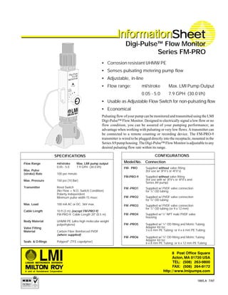
- 1. SPECIFICATIONS InfoInfoInfoInfoInforrrrrmationmationmationmationmationSheetSheetSheetSheetSheetInfoInfoInfoInfoInforrrrrmationmationmationmationmation Pulsating flow of your pump can be monitored and transmitted using the LMI Digi-Pulse™ Flow Monitor. Designed to electrically signal a low flow or no flow condition, you can be assured of your pumping performance; an advantage when working with pulsating or very low flows. A transmitter can be connected to a remote counting or recording device. The FM-PRO-9 transmitter is wired to be plugged directly into the receptacle, mounted in the SeriesA9pumphousing.TheDigi-Pulse™FlowMonitorisadjustabletoany desired pulsating flow rate within its range. Flow Range ml/stroke Max. LMI pump output 0.05 - 5.0 7.9 GPH (30.0 l/h) Max. Pulse (stroke) Rate 100 per minute Max. Pressure 150 psi (10 Bar) Transmitter Reed Switch (No Flow = N.O. Switch Condition) Polarity Independent Minimum pulse width 15 msec Max. Load 100 mA AC or DC, 36V max. Cable Length 10 ft (3 m) (except FM-PRO-9) FM-PRO-9: Cable Length 20" (0.5 m) Body Material UHMW PE (ultra high molecular weight polyethylene) Valve Fitting Material Carbon Fiber Reinforced PVDF (where supplied) Seals & O-Rings Polyprel® (TFE copolymer) • Corrosion resistant UHMW PE • Senses pulsating metering pump flow • Adjustable, in-line • Flow range: ml/stroke Max. LMI Pump Output 0.05 - 5.0 7.9 GPH (30.0 l/h) • Usable as Adjustable Flow Switch for non-pulsating flow • Economical Digi-Pulse™ Flow Monitor Series FM-PRO 1865.A 7/97 CONFIGURATIONS ModelNo. Connection FM- PRO Supplied without valve fitting (for use w/ 3FV’s or 4FV’s) FM-PRO-9 Supplied without valve fitting (for use with w/ 3FV’s or 4FV’s and Series A9 pump) FM -PRO1 Supplied w/ PVDF valve connection for 1 /4" OD tubing FM -PRO2 Supplied w/ PVDF valve connection for 3 /8" OD tubing FM -PRO3 Supplied w/ PVDF valve connection for 1 /2" OD tubing (or 9 x 12 mm) FM -PRO4 Supplied w/ 1 /4" NPT male PVDF valve housing FM -PRO5 Supplied w/ 1 /4" OD fitting and Metric Tubing Adapter Kit for: 3 x 6 mm PE Tubing; or 4 x 6 mm PE Tubing FM -PRO6 Supplied w/ 3 /8" OD fitting and Metric Tubing Adapter Kit for: 6 x 8 mm PE Tubing; or 6 x 12 mm PE Tubing
- 2. InstructionInstructionInstructionInstructionInstruction SheetSheetSheetSheetSheet Digi-Pulse™ Flow Monitor Series FM-PRO 1865.A 7/97 1. With your pump turned off, screw the lower valve fitting of the Digi-Pulse™ Flow Monitor to the discharge side of the pump head. 2. Remove the red Caplug from the top of the Digi-Pulse™. Be sure to save the O-ring seal and spacer. Attach your 3FV or 4FV to the top of the Digi-Pulse™. 3. Connect the Digi-Pulse™ cable to your counter, computer, or other recording device (polarity is not critical). If cable extension is desired, consult factory. Plug the FM-PRO-9 cable directly into the receptacle in the Series A9 pump housing. 4. Loosen the locknut of the flow-range knob of the flow monitor and set the knob to the largest dot. Start the pump and adjust it (calibrate, if necessary) for proper output to satisfy your system requirements. 5. With the pump running, gradually turn the adjustment knob of the flow monitor counter-clockwise until the sensor just begins to trigger your electronic device. This will be the most sensitive setting of the Digi-Pulse™, given your pump setting and fluid properties. Every stroke of the pump will output enough volume of solution to cause the Digi- Pulse™ flow monitor to register a pulse. If the flow drops below the initial pump setting, the Digi-Pulse™ will no longer register strokes to your electronics, indicating some type of pump failure or low-level condition. 6. Tighten the adjustment locknut without altering the adjustment position. Note: After the initial pump and Digi-Pulse™ setup is complete, any adjustment of the stroke length of the pump (output per stroke) will require a readjustment of the Digi-Pulse™ flow monitor (repeat steps 4 - 6 above). To change the flow range setting: A set screw holds the transmitter body in a notch on the side of the flow monitor. Remove the screw and washer and slide or turn the transmitter 180° to an alternate position and tighten the screw and washer in the hole to secure the transmitter. The Digi-Pulse™ Flow Monitor comes factory set at the “LOW” setting which should accommodate most applications. However, the “INTERMEDIATE” or “HIGH” settings may be appropri- ate for a particular application if the sensor does not trigger in the “LOW” setting. Digi-Pulse is a trademark of Liquid Metronics, Inc. Polyprel is a registered trademark of Liquid Metronics, Inc.