flight simulation integration of flight control system in simulation
1.
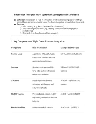
1. Introduction toFlight Control System (FCS) Integration in Simulation
● Definition: Integration of FCS in simulation involves replicating real-world flight
control laws, sensors, actuators, and feedback loops in a simulated environment.
● Purpose:
○ Pilot training (e.g., FAA/ICAO-certified simulators).
○ Aircraft design validation (e.g., testing control laws before physical
prototyping).
○ Research (e.g., handling qualities analysis).
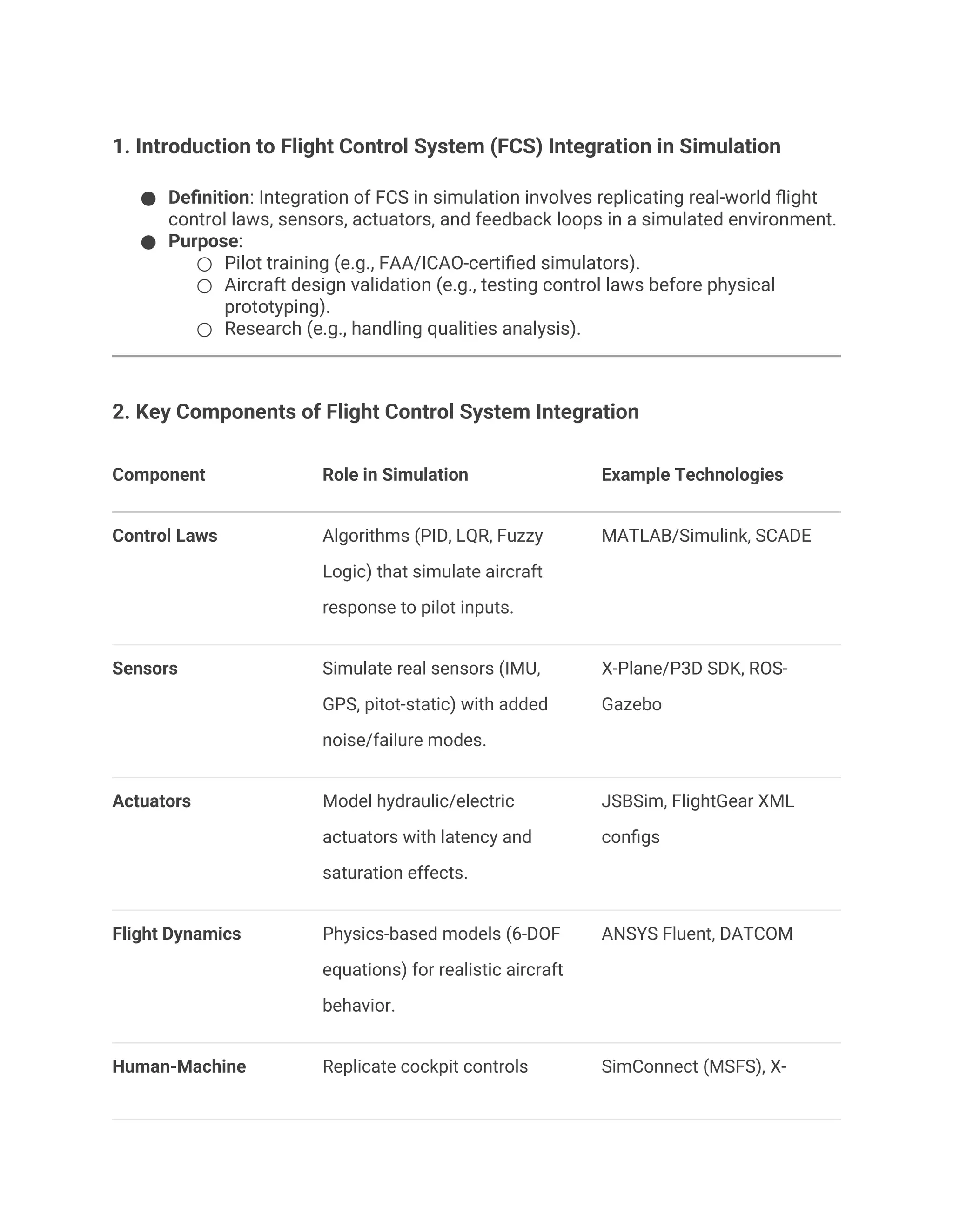
2. Key Components of Flight Control System Integration
Component Role in Simulation Example Technologies
Control Laws Algorithms (PID, LQR, Fuzzy
Logic) that simulate aircraft
response to pilot inputs.
MATLAB/Simulink, SCADE
Sensors Simulate real sensors (IMU,
GPS, pitot-static) with added
noise/failure modes.
X-Plane/P3D SDK, ROS-
Gazebo
Actuators Model hydraulic/electric
actuators with latency and
saturation effects.
JSBSim, FlightGear XML
configs
Flight Dynamics Physics-based models (6-DOF
equations) for realistic aircraft
behavior.
ANSYS Fluent, DATCOM
Human-Machine Replicate cockpit controls SimConnect (MSFS), X-
2.
Interface (HMI) (yoke,pedals) and displays
(PFD, MFD).
Plane UDP protocols
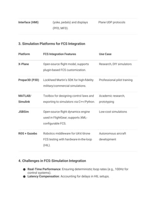
3. Simulation Platforms for FCS Integration
Platform FCS Integration Features Use Case
X-Plane Open-source flight model, supports
plugin-based FCS customization.
Research, DIY simulators
Prepar3D (P3D) Lockheed Martin’s SDK for high-fidelity
military/commercial simulations.
Professional pilot training
MATLAB/
Simulink
Toolbox for designing control laws and
exporting to simulators via C++/Python.
Academic research,
prototyping
JSBSim Open-source flight dynamics engine
used in FlightGear; supports XML-
configurable FCS.
Low-cost simulations
ROS + Gazebo Robotics middleware for UAV/drone
FCS testing with hardware-in-the-loop
(HIL).
Autonomous aircraft
development
4. Challenges in FCS-Simulation Integration
● Real-Time Performance: Ensuring deterministic loop rates (e.g., 100Hz for
control systems).
● Latency Compensation: Accounting for delays in HIL setups.
3.
● Fidelity Trade-offs:Balancing computational complexity vs. realism (e.g., CFD
vs. lookup tables).
● Failure Mode Simulation: Injecting sensor/actuator failures for robustness
testing.
5. Case Study: Integrating Fly-by-Wire (FBW) in Simulation
● Objective: Simulate Airbus A320’s FBW laws in X-Plane.
● Steps:
1. Model control laws in Simulink.
2. Export to C++ using Simulink Coder.
3. Link to X-Plane via UDP (using XPLMPlugin).
4. Validate against real-world performance data.
● Outcome: Achieved 90% match in handling qualities vs. certified Level-D
simulator.
6. Metrics for Evaluation
Metric Measurement Method Ideal Value
Step Response
Time
Time to reach 90% of commanded
pitch/roll.
<1 sec for commercial
jets
Steady-State
Error
Deviation from desired altitude/heading. <1%
Phase Margin Stability analysis via Bode plots. >30°
Hardware Latency Round-trip delay (input →
simulation → output).
<10 ms
7. References
4.
● FAA AC120-40B (Airplane Simulator Qualification).
● Stevens, B. L., & Lewis, F. L. (2015). Aircraft Control and Simulation. Wiley.
● X-Plane Developer Docs: developer.x-plane.com.
● MathWorks Aerospace Blockset: Control Law Design.
8. Future Trends
● AI/ML: Adaptive control laws trained in simulation (e.g., OpenAI’s drone control).
● Digital Twins: Real-time synchronization between physical aircraft and
simulation.
● Quantum Computing: High-fidelity CFD in real-time for FCS testing.