This document describes a flexible wearable antenna integrated with an electromagnetic band gap (EBG) structure using polydimethylsiloxane (PDMS) as the substrate. The EBG reduces radiation into the human body by 17 dB and decreases frequency detuning impacts. The antenna has a bandwidth of 8.3% covering 2.4 GHz and improved gain of 7 dBi. Specific absorption rate assessment shows the integrated EBG reduces SAR values to 0.03 W/kg when 1 mm from a tissue model, meeting safety standards. The flexible antenna with EBG is a good candidate for wearable medical devices due to its performance and safety characteristics.
![TELKOMNIKA, Vol.15, No.3, September 2017, pp. 1454~1460
ISSN: 1693-6930, accredited A by DIKTI, Decree No: 58/DIKTI/Kep/2013
DOI: 10.12928/TELKOMNIKA.v15i3.7214 1454
Received May 1 2017; Revised July 2, 2017; Accepted July 18, 2017
Flexible Wearable Antenna on Electromagnetic Band
Gap using PDMS substrate
Adel Y. I. Ashap
1
, Z. Z. Abidin*
2
, S.H. Dahlan
3
, H. A. Majid
4
, S.K. Yee
5
, Gameel Saleh
6
,
Norun Abdul Malek
7
1,2,3,4,5
Research Center of Applied Electromagnetics, Faculty of Electrical and Electronic Engineering,
Universiti Tun Hussein Onn Malaysia (UTHM), Batu Pahat, Johor, Malaysia
6
Biomedical Engineering Department, College of Engineering, University of Dammam, Dammam 1982,
Saudi Arabia
7
Kulliyah of Engineering, Electrical and Computer Engineering Department, International Islamic University
Malaysia (IIUM), P.O. Box 10, 50728 Kuala Lumpur, Malaysia
*Corresponding author, e-mail: zuhairia@uthm.edu.my
Abstract
A robust and low-profile electromagnetic band-gap (EBG) based on flexible wearable antenna
covering 2.4 GHz frequency band is presented. The incorporated EBG with antenna reduces the radiation
into the human body around 17 dB and decreases the impacts of frequency detuning. The overall
dimension of the antenna integrated with EBG is 56 x 56 x 4 mm3 with relative impedance bandwidth of
8.3% is achieved. The proposed design has improved the gain up to 7 dBi. Specific absorption rate (SAR)
assessment is also studied to certify the performance of the antenna when it is located proximity to human
tissue. The flexible antenna with aforementioned performances could be chosen as a good candidate for
integration into a range of wearable devices for medical application.
Keywords: EBG, wearable antennas, PDMS, SAR
Copyright © 2017 Universitas Ahmad Dahlan. All rights reserved.
1. Introduction
Wearable antennas are vital element for wireless devices in a body-area network
(BAN). They obtain a numerous used by health care suppliers because of their potential
relevance in different fields, such as tracking, smart houses, observing of human vital signs,
patient, and battlefield survival [1]. As a rapidly growing research field, wearable antennas have
grown an awesome amount of interest from both researchers; industry and academia due to
their nontraditional operating environment-placed in extremely close proximity to the human
body tissue. Accordingly, a demand of high radiation efficiency antenna while loading on human
body makes the design a challenging task especially when it is required to be a low-profile, light-
weight and robust characteristics. Furthermore, the influence of the wearable antenna on
human body, characterized by the specific absorption rate, (SAR) [2-3] needs to take into
account with safety level to insure that there is no impact on the human bodies and the value is
minimized.
Over the previous decade, various antenna types have been investigated and
documented for their suitability as wearable antennas including inverted-F antennas [4], cavity-
backed or planar waveguide fed slots [5, 6], patch antennas [7] and monopole antennas [8].
Nevertheless, these antenna have disadvantages either/or high profile, narrow bandwidth and
large footprints, that result in limited used in the application of wearable devices. More recently,
electromagnetic band-gap (EBG) surfaces integrated with wearable antenna have been
proposed and reported to enable and provide a high degree of isolation from the human body
[1, 9-12]. However, some drawbacks still presents in the current EBG backed antenna designs
such as poor front-to back ratio [11], relatively electrically large [9,10], rigid [12] and semi
flexible [1].
In this paper, a compact flexible and robust wearable antenna incorporated with a
compact footprint and low-profile EBG for wearable medical application is presented using
polydimethylsiloxane (PDMS) as substrate.](https://image.slidesharecdn.com/577214-200911075653/75/Flexible-Wearable-Antenna-on-Electromagnetic-Band-Gap-using-PDMS-substrate-1-2048.jpg)
![TELKOMNIKA ISSN: 1693-6930
Flexible Wearable Antenna on EBG using PDMS substrate (Adel Y. I. Ashap)
1455
(a) (b) (c) (d)
Figure 1. Geometry and dimensions (a) top view of monopole antenna, (b) bottom view of
monopole antenna, (c) top view of the EBG structure, and (d) metallic backing view of the EBG
structure
2. Antenna and EBG Design
The proposed microstrip monopole antenna is designed on 1 mm thick PDMS with a
dielectric constant of 2.8 and loss tangent of 0.02 as showed in Figure 1 (a) and (b). The overall
dimension of the antenna is 40 × 22 mm
2
. A copper tape as conductive materials with thickness
of 0.1 mm is used as metallic layer.
The antenna is placed on a top of EBGs array that works as an artificial magnetic
conductor (AMC). The benefit of the used of AMC is help to improve the performance of the
antenna when it is located on the human body. The EBG array consists of 2 x 2 elements
constructed on the same PDMS substrate as the antenna with 2 mm thick as depicted in Figure
1 (c) and (d). 1 mm Rohacell foam is inserted between antenna and EBG to avoid short circuit
and to reduce the impedance mismatch. The overall dimension is 56 × 56 × 4 mm
3
.
Figure 2. Suspended microstrip line method.
3. Analysis and Discussion
Two methods been used to investigate the EBGs characteristic at the demand
frequency; (a) suspended transmission line and (b) reflection phase methods [13]. For the
suspended transmission line method, an insulate microstrip transmission line is positioned over
the EBG to be characterized as shown in Figure 2. Meanwhile, for the reflection phase
technique, the boundaries of the BEG unit cell model are defined as unit cell as to represents an
infinite structure. All the simulations process are performed in CST Microwave Studio® [14].
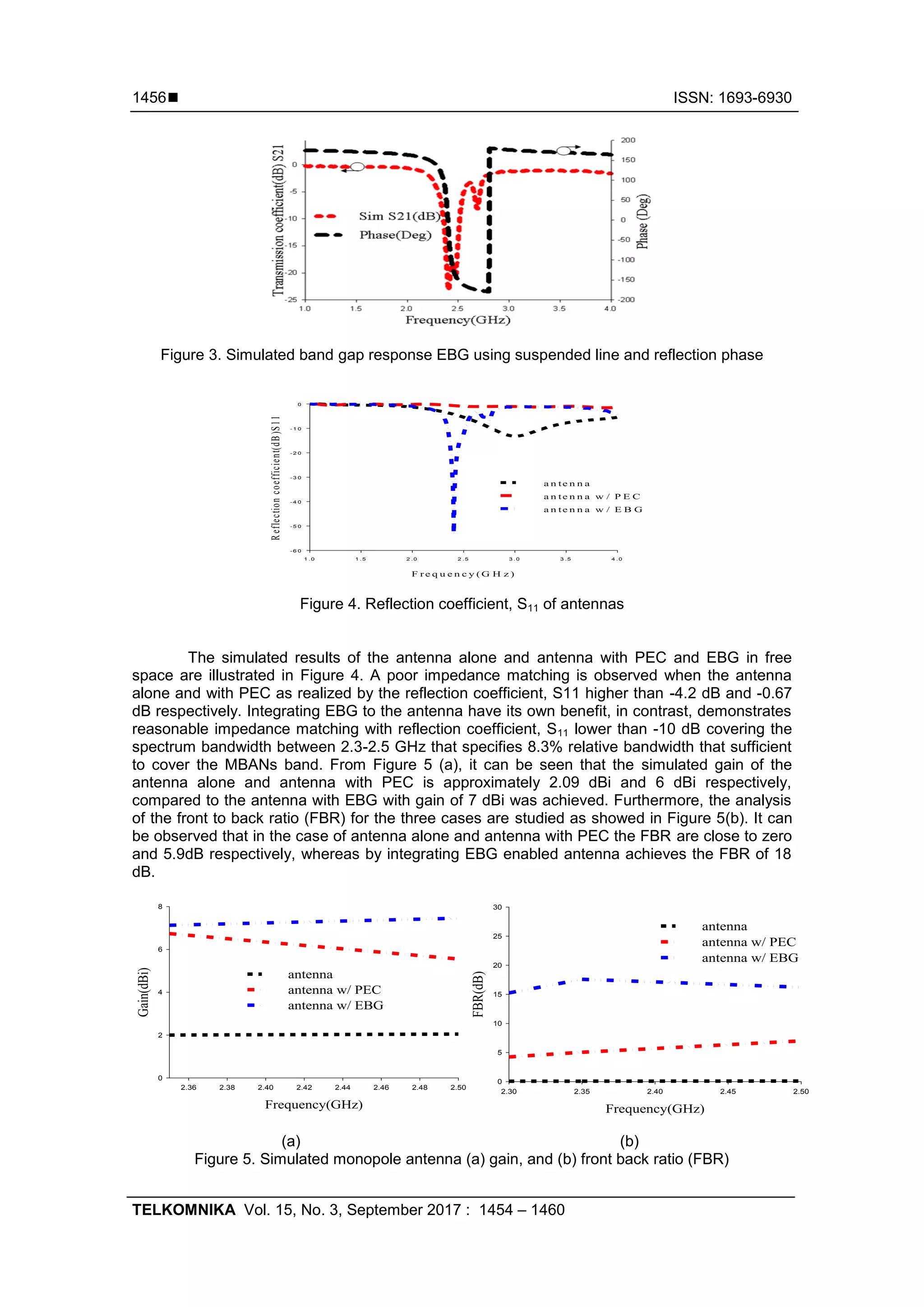
From Figure 3, it can be observed that the proposed EBG structures can reflect normally
incident electromagnetic wave with a zero phase shift at a frequency of 2.4 GHz (black color),
while the suspended line examined a sufficiently well-defined band gap in the range of 2.36
GHz to 2.52 GHz (red color).](https://image.slidesharecdn.com/577214-200911075653/75/Flexible-Wearable-Antenna-on-Electromagnetic-Band-Gap-using-PDMS-substrate-2-2048.jpg)
![ ISSN: 1693-6930
TELKOMNIKA Vol. 15, No. 3, September 2017 : 1454 – 1460
1458
Frequency (GHz)
1.0 1.5 2.0 2.5 3.0 3.5 4.0
Reflectioncoefficient,S11(dB)
-30
-25
-20
-15
-10
-5
0
R=70 mm
R=80 mm
R=100 mm
R=140 mm
Figure 8. Reflection coefficient ,S11 of integrated EBG-enabled antenna on bending effects with
difference diameters
4.2. Specific Absorption Rate (SAR)
SAR investigation was carried out using CST MWS simulator. This has been
demonstrated by located a human model in the vicinity of the incorporated antenna with EBGs.
The cylindrical model was used as to mimic the human arm with multilayer human tissue. The
model has an outer radius of 40 mm and consist of a 13mm thick bone layer with relative
permittivity of 18.49 and conductivity values of 0.82 S/m, a 20-mm-thick muscle layer with
relative permittivity of 52.67 and conductivity values of 1.77 S/m a 5-mm-thick fat layer with
relative permittivity of 5.27 and conductivity values of 0.11 S/m, and 2-mm-thick skin layer with
relative permittivity of 37.95 and conductivity values of 1.49 S/m. This data has been taken from
previously reported studies of [14]. The model is placed 1mm from the incorporated antenna
with EBG ground.
The input power used to analyze the SAR value is 100 mm as a benchmark. The
calculation is based on the IEEE C95.1 standard and averaged over 1g of biological tissue.
Based on the guidelines specified by FCC standard, the SAR values must be not exceeding 1.6
W/kg averaged over 1g of tissue [15].
(a) (b)
Figure 9. Simulated SAR values for (a) the antenna alone and (b) the integrated EBG-enabled
antenna at 1mm away from the tissue model
The SAR performance is compared between the antenna alone and with EBG as shown
in Figure 9. The antenna has maximum 1g averaged SAR value of about 6.6 W/kg because of
its omnidirectional radiation characteristic. Even the antenna is placed at 5 mm away from the
model tissue but still realized a maximum 1g averaged SAR value as high as 5.3 W/kg,, as seen](https://image.slidesharecdn.com/577214-200911075653/75/Flexible-Wearable-Antenna-on-Electromagnetic-Band-Gap-using-PDMS-substrate-5-2048.jpg)
![TELKOMNIKA ISSN: 1693-6930
Flexible Wearable Antenna on EBG using PDMS substrate (Adel Y. I. Ashap)
1459
in Table 1. Adding EBG to the antenna, a more reduction is noticed in the maximum 1 g
averaged SAR value dropping to 0.03 W/kg even when the antenna with EBG is only 1 mm
away from the model tissue. Furthermore, EBG has benefited the antenna by showing a
significant reduction of SAR that has been achieved. Table 2 shows the comparison of various
SAR values obtained with and without the EBG structure presented by previous researchers.
Table 1. Maximum 1g averaged SAR value for the antenna, the integrated EBG with
antenna at different distances away from the tissue model (units: w/kg)
Distance 1 mm 3 mm 5 mm
Antenna 6.6 6 5.3
Antenna with EBG 0.03 0.02 0.01
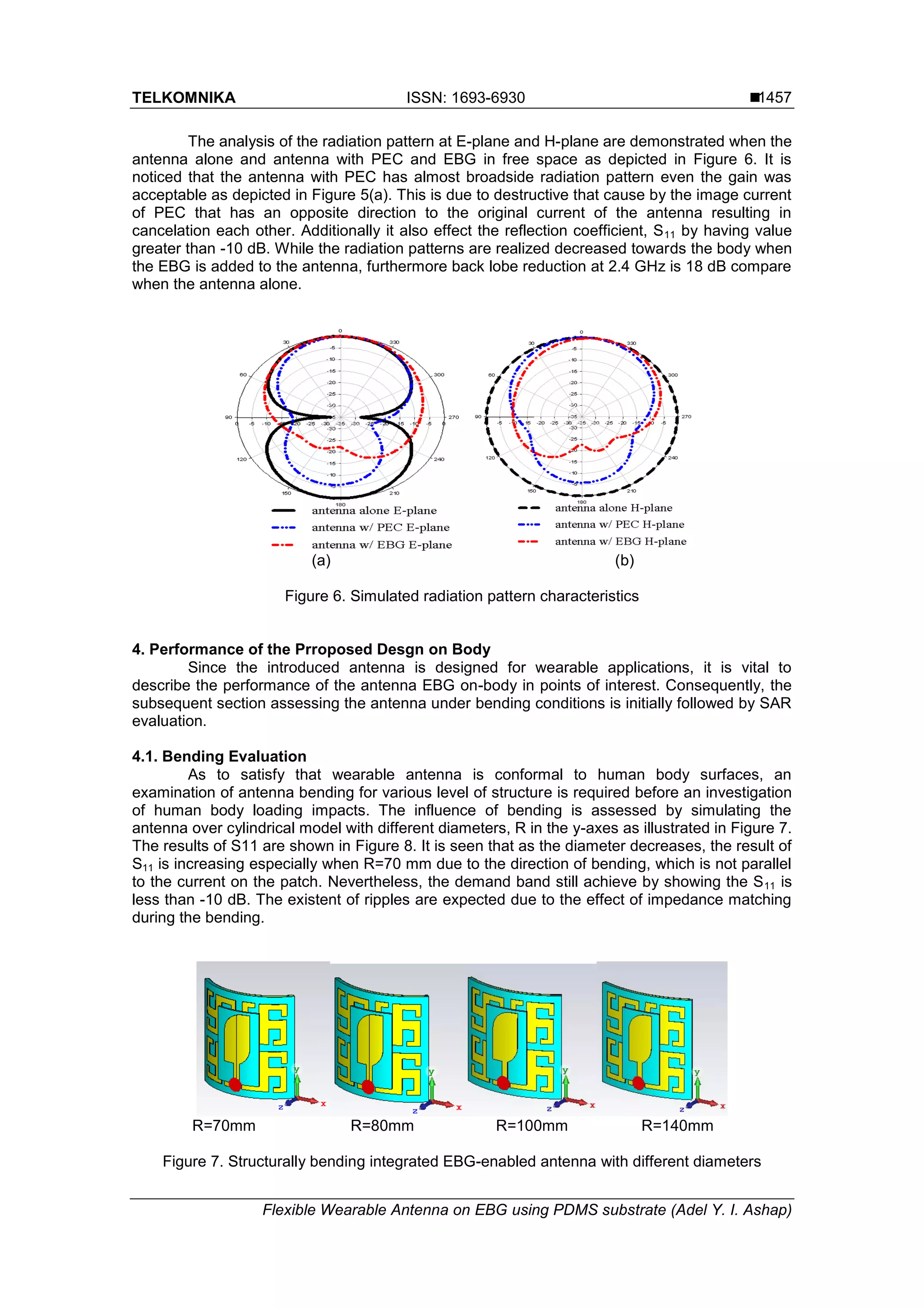
The influence on the antenna performance at several distances from the human tissue
model for antenna a lone and with EBG are shown in Figure 10 (a) and Figure 10(b)
respectively. It is obvious that the reflection coefficient, S11 for the incorporated antenna with
EBG shows reasonable S11 results compared to the antenna alone. It can be noticed that, from
Figure 10(a), the resonance frequencies are shifted proportionally by the distance, d. This is
might be due to the conductivity of body with the antenna. Additionally, the gain of the
incorporated structural is well-maintained when it is located on the human model, showing a
stable gain of 6.8 dBi.
Table 2. Shows the various SAR values obtained with and without the EBG
structure
Ref SAR Value of antenna (w/kg) SAR Value with EBG (w/kg)
[12] 13.5 0.29
[1] 16.8 0.66
[11] 1.88 0.683
[9] 13.85 0.079
This work 6.6 0.03
Frequency(GHz)
1.0 1.5 2.0 2.5 3.0 3.5 4.0
Reflectioncoefficient(dB)S11
-25
-20
-15
-10
-5
0
d=1 mm
d=2 mm
d=3 mm
d=5 mm
Frequency(GHz)
1.0 1.5 2.0 2.5 3.0 3.5 4.0
Reflectioncoefficient(dB)S11
-40
-30
-20
-10
0
d=1 mm
d=2 mm
d=3 mm
d=5 mm
(a) (b)
Figure 10. Simulated S11 for (a) the antenna alone and (b) the integrated EBG-enabled antenna
at different distances (d) away from the tissue model
5. Conclusions
A conformal flexible incorporated antenna with EBG with a low-profile, robust and
compact footprint, has been introduced for wearable applications. It was clearly that the
presented EBG integrated antenna achieved an impedance bandwidth of 8.3 % with 7 dBi gain.
The impacts under bending condition of the design were demonstrated. The integrated design
has shown a good performance when it was loaded to human body by maintaining a good
return loss and reduced SAR values.](https://image.slidesharecdn.com/577214-200911075653/75/Flexible-Wearable-Antenna-on-Electromagnetic-Band-Gap-using-PDMS-substrate-6-2048.jpg)
![ ISSN: 1693-6930
TELKOMNIKA Vol. 15, No. 3, September 2017 : 1454 – 1460
1460
Acknowledgement
The authors of this paper wish to acknowledge the funding of this project by Ministry of
Education Malaysia (MOE) under Research Accularation Collaborative Effort (RACE) Vot No.
1510 and GPPS Vot No. U739.
References
[1] Z Jiang, DE. Brocker, PE. Sieber, DH Werner. A compact, low-profile metasurface-enabled antenna
for wearable medical body-area network devices. IEEE Trans. Antennas Propag. 2014; 62(8):4021–
4030.
[2] RA. Abd-Alhameed, PS. Excell, MA. Mangoud. Computation of specific absorption rate in the human
body due to base-station antennas using a hybrid formulation. IEEE Trans. Electromagn. Compat.
2005; 47(2):374–381.
[3] RA. Abd-Alhameed, PS. Excell, AM. Mangoud. A Hybrid Computational Electromagnetics
Formulation for Simulation of Antennas Coupled to Lossy Dielectric Volumes. IEEE Trans. Broad.
2004; 50(3):253–259.
[4] PJ. Soh, GAE. Vandenbosch, SL. Ooi, NHM. Rais. Design of a broadband, all-textile slotted PIFA.
IEEE Trans. Antennas Propag. 2012; 60(1): 379-384.
[5] N Haga, K Saito, M Takahashi, K Ito.Characteristics of cavity slot antenna for body-area networks.
IEEE Trans. Antennas Propag. 2009; 57(4):837–843.
[6] R Moro, S Agneessens, H Rogier, M Bozzi. Wearable textile antenna in substrate integrated
waveguide technology. Electron. Lett. 2012; 48(16):985.
[7] A Alomainy, Y Hao, A Owadally, CG Parnini, Y. Nechayev, CC Constantinou, PS. Hall. Statistical
analysis and performance evaluation for on-body radio propagation with microstrip patch antennas.
IEEE Trans. Antennas Propag. 2007; 55(1): 245–248.
[8] PS. Hall, Y. Hao, YI. Nechayev, A. Alomainy, CC. Constantinou, C. Parini, MR. Kamarudin, TZ.
Salim, DTM. Hee, R. Dubrovka, AS. Owadall, W. Song, AA. Serra, P. Nepa, M. Gallo, M. Bozzetti.
Antennas and propagation for on-body communication systems. IEEE Antennas Propag. Mag.vol.
2007; 49(3) 41–58.
[9] S. Zhu, R. Langley. Dual-band wearable textile antenna on an EBG substrate. IEEE Trans.
Antennas Propag .2009; 57(4): 926–935.
[10] S. Velan, EF. Sundarsingh, M. Kanagasabai, AK. Sarma, C. Raviteja, R. Sivasamy, JK. Pakkathillam.
Dual-Band EBG Integrated Monopole Antenna Deploying Fractal Geometry for Wearable
Applications. IEEE Ant. Wire. Propag. Lett. 2015; 14: 249-252.
[11] HR. Raad, AI. Abbosh, HM. Al-Rizzo, DG. Rucker. Flexible and compact AMC based antenna for
telemedicine applications. IEEE Trans. Antennas Propag. 2013; 61(2): 524–53.
[12] YS. Chen, TY. Ku. A Low-Profile Wearable Antenna Using a Miniature High Impedance Surface for
Smartwatch Applications, in IEEE Antennas and Wireless Propagation Letters. 2016; 15: 1144- 1147.
[13] Aminian A, F Yang, Y Rahmat-Samii, In-phase reflection and EM wave suppression characteristics of
electromagnetic band gap ground planes, Proceedings of the IEEE Antennas and Propagation
Society International Symposium. 2003; 4:430–433.
[14] CST Microwave Studio [Online]. Available: http/www.cst.com.
[15] MA. Stuchly, SS. Stuchly .Dielectric properties of biological substances-tabulated. J. Microw.
Power.1980; 15(1):19-26.
[16] http://www.fcc.gov/encyclopedia/specific-absorption-rate-sar-cellulartelephones](https://image.slidesharecdn.com/577214-200911075653/75/Flexible-Wearable-Antenna-on-Electromagnetic-Band-Gap-using-PDMS-substrate-7-2048.jpg)


