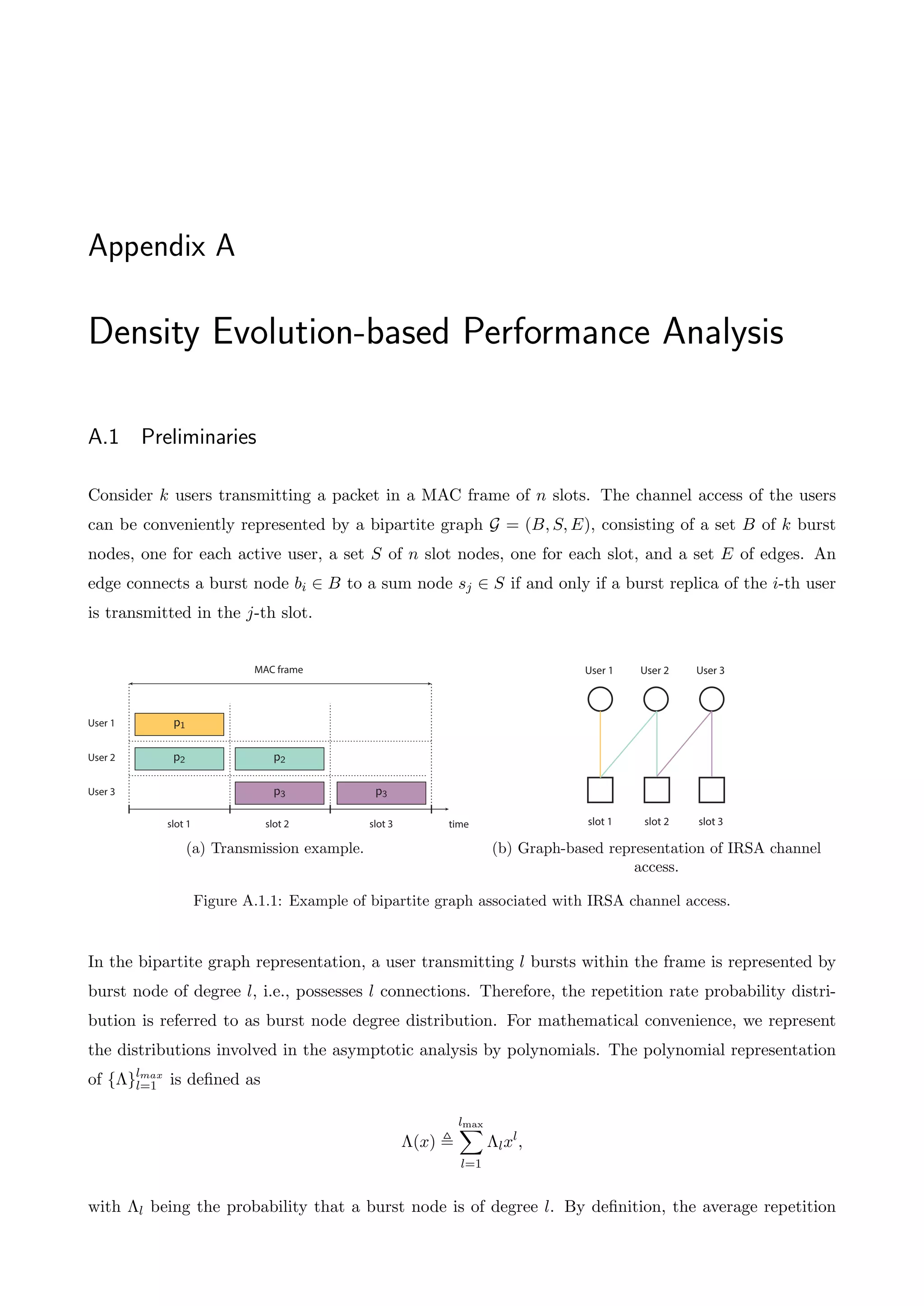
Finite-Length Performance Analysis of Slotted ALOHA with Interference Cancellation analyzes the performance of Irregular Repetition Slotted ALOHA (IRSA) for finite frame lengths. It develops a matrix-based analysis to derive a semi-analytical expression for packet loss rate. Through computer simulations, it shows the proposed analysis allows exact computation of packet loss rate for small user numbers and frame lengths, unlike previous asymptotic analyses for infinite users and frames.


![Chapter 1
Introduction
1.1 Background
A multiple access network entails several transmitters — referred to as users — communicating with
a single receiver over a shared communication channel. For instance, mobile phones transmitting to a
base station, ground stations communicating with a satellite and personal computers communicating
with a wireless access point are all examples of a multiple access network. A fundamental problem
arising in these networks is the potential contention of the users for the channel resources. More
particularly, if multiple users access the channel simultaneously, their packet transmissions will inter-
fere with each other at the receiver, i.e., a collision will occur, typically resulting in the loss of the
transmitted packets. Therefore, a Medium Access Control (MAC) scheme arbitrating transmissions
over the common channel is of paramount importance when it comes to meaningful communication
and efficient utilization of resources.
In general, MAC schemes can be divided into two major categories, coordinated and uncoordinated,
i.e., random, access schemes. In coordinated access schemes, a central unit such as a base station
allocates the channel resources to the users either in time or in frequency using Time Division Multiple
Access (TDMA) [3] or Frequency Division Multiple Access (FDMA) [4] respectively. Although these
schemes eliminate the probability of having collisions, they require the knowledge of the number
of users connected to the network as well as a relatively steady traffic for each user. In contrast,
random access schemes are distribute protocols that allow the dynamic assignment of the channel to
an unknown number of users with relatively bursty traffic.
The first random access network was the popular ALOHA, developed in 1970 at the university of
Hawaii under the guidance of Abramson [1]. In ALOHA, users access the channel as soon as they
have a packet available to transmit to the receiver. However, if several users transmit concurrently, a
collision will occur and the receiver will discharge the collided packets. Collision resolution is referred
to the process of recovering the collided packets. In ALOHA, collision resolution is done by means of
feedback and retransmissions. In more detail, the receiver acknowledges the successfully transmitted](https://image.slidesharecdn.com/finite-lengthperformanceanalysisofslottedaloha-thesis-220518201551-91ff873d/75/Finite-Length-Performance-Analysis-of-Slotted-ALOHA-Thesis-pdf-11-2048.jpg)
![2 1. Introduction
packets through a feedback channel. Thus, the users who transmit and do not receive an acknowledg-
ment infer that their packet was involved in a collision and in response they retrasmit it after waiting
a random period of time. This retransmission process is executed by the users who experienced a
collision until the successful transmission of their packet.
time
User 1
User 2
User 3 p3
Receiver
p1
p2
collision
Figure 1.1.1: Overview of a collision in ALOHA. There are three packets involved in the collision.
Although the simplicity of random MAC schemes, they su↵er from collisions, which lead to poor
system performance, i.e., long delays due to successive collisions and retransmissions of the collided
packets. A metric commonly used in literature for the performance assessment of random access
schemes is throughput, defined as the expected number of successfully transmitted packets per time
unit. Throughput metric indicates how efficiently the shared channel is used. For example, the peak
throughput of ALOHA is 1/2e ⇡ 0.18 packets/(time unit), which implies that only 18% of the time
the channel is used to carry meaningful traffic.
A simple yet e↵ective enhancement of ALOHA is slotted ALOHA (SA) [2]. In SA, time is divided
into equal length intervals called slots. Packets are of the same length as slots and users are allowed
to transmit a packet only at the beginning of a slot. This minimum coordination in users’ transmis-
sions aims at reducing the probability of overlapping transmissions and hence the chance of collisions.
Indeed, the peak throughput of SA is 1/e ⇡ 0.37 packets/slot, resulting in a gain of almost 50% with
respect to original ALOHA.
slot collision
time
User 1
User 2
User 3 p3
Receiver
p1
p2
p2
Figure 1.1.2: Overview of a collision in slotted ALOHA. There are two packets involved in the collision.](https://image.slidesharecdn.com/finite-lengthperformanceanalysisofslottedaloha-thesis-220518201551-91ff873d/75/Finite-Length-Performance-Analysis-of-Slotted-ALOHA-Thesis-pdf-12-2048.jpg)
![1.2. Literature Review 3
During the past decades, many variations of SA scheme were introduced by the research community,
such as tree algorithms [7], Carrier Sense Multiple Access (CSMA) [8], etc. However until recently, all
random access schemes were treating collided packets as a waste and were hence relying on retrans-
missions to resolve collisions. This approach has now changed with the advent of sophisticated signal
processing techniques such as Multiuser Detection (MUD) [5] and iterative interference cancellation
(IIC) [6]. The underlying idea of IIC is that interference caused by multiple concurrent transmissions
has some structure, as opposed to background random noise, which can be exploited in order to be
cancelled. From a packet-based point of view, a collision in a slot conveys some information about
the collided packets, which can be potentially used for cancelling the interference contribution of a
collided packet on that slot. For example, assume that the receiver has decoded a packet, say p1,
in a collision-free slot s and that there is a collision between p1 and another packet, say p2, in a
subsequent slot s0. According to the classical collision model, no information about p1 and p2 can be
extracted from slot s0, therefore slot s0 is discharged by the receiver and packet p2 is lost. However, a
IIC-enabled receiver will remove the interference caused by the known packet p1 from slot s0 and will
recover packet p2. This motivation example is depicted in the figure below.
time
User 1
User 2
Receiver
p1
p2
slot s slot s’
p1
p1
(a) Received packets before the IIC operation.
time
User 1
User 2
Receiver
p1
p2
slot s slot s’
p1
p1 p2
(b) Received packets after the IIC operation.
Figure 1.1.3: Schematic representation of the interference cancellation operation. Transparent boxes illustrate
packets that were decoded and their interference contribution on the corresponding slots have been cancelled.
1.2 Literature Review
The throughput gain in applying IIC to SA framework has been initially formalized in contention
resolution diversity slotted ALOHA (CRDSA) [9]. In CRDSA scheme, each packet is transmitted in
two di↵erent randomly selected slots. This, in part, increases the physical channel load, but it provides](https://image.slidesharecdn.com/finite-lengthperformanceanalysisofslottedaloha-thesis-220518201551-91ff873d/75/Finite-Length-Performance-Analysis-of-Slotted-ALOHA-Thesis-pdf-13-2048.jpg)
![4 1. Introduction
time diversity through the transmission of a redundant copy of each packet. Furthermore, this extra
copy assists the receiver to resolve collisions through IIC. This is possible since each packet contains
a pointer to the slot wherein its twin packet was sent. Whenever a packet is decoded, the pointer
is extracted and the potential interference caused by its twin packet on the corresponding slot is
removed. This procedure is iterated, hopefully permitting the decoding of more packets. This results
in remarkably improved throughput, which may reach 0.55 packets/slot while the peak throughput
for SA is 0.37 packets/slot.
A generalization of CRDSA has been proposed by Liva in [10], dubbed IRSA. Similarly to CRDSA,
each user attempts to communicate his packet to the receiver by transmitting multiple copies of it
in randomly selected slots. However, the number of copies that each user sends per packet, i.e.,
the repetition rate, is neither limited to two copies nor fixed to a deterministic value. In fact, it is
drawn from a probability distribution. For the performance evaluation of IRSA, Liva introduced a
novel bipartite graph representation of the scheme, establishing in this way a bridge between the IIC
process of IRSA and the iterative decoding of channel codes on graphs, i.e., low-density parity-check
(LDPC) codes [11], [12]. This enabled him to apply density evolution [13] to the case of IRSA. Density
evolution is a theoretical method for evaluating the performance of LDPC codes as the code length
goes to infinity, namely in the asymptotic setting. Similarly, Liva employed density evolution to study
the performance of IRSA as the number of slots available for decoding tends to infinity. The key
result of his work is an upper bound on the achievable throughput of the scheme. In particular, he
showed that via proper selection of the repetition rate probability distribution IRSA may achieve peak
throughput close to 1 packets/slot asymptotically.
1.3 Goal and Contribution of the Thesis
Looking at the literature [15–18], we realize that most of the works on IRSA schemes are concerned
with the asymptotic setting of infinitely long MAC frames, enabling in this way a performance analysis
based on density evolution. Since this approach gives an upper bound on the peak throughput, the
problem of deriving an exact performance analysis is still an open problem. With this work, we aim
at filling this gap and extend the theoretical study of IRSA schemes to the case of finite-length MAC
frames.
Our approach is based on combinatorics. In particular, we identify the similarities between the trans-
mission strategy of IRSA and matrix occupancy problems [19]. Exploiting this analogy, we derive a
semi-analytic expression for the exact computation of throughput and packet loss rate (PLR) metrics,
given the number of users, the number of slots per MAC frame, and the repetition rate probability
distribution.
However, the proposed analysis su↵ers from high computational complexity and therefore can be](https://image.slidesharecdn.com/finite-lengthperformanceanalysisofslottedaloha-thesis-220518201551-91ff873d/75/Finite-Length-Performance-Analysis-of-Slotted-ALOHA-Thesis-pdf-14-2048.jpg)

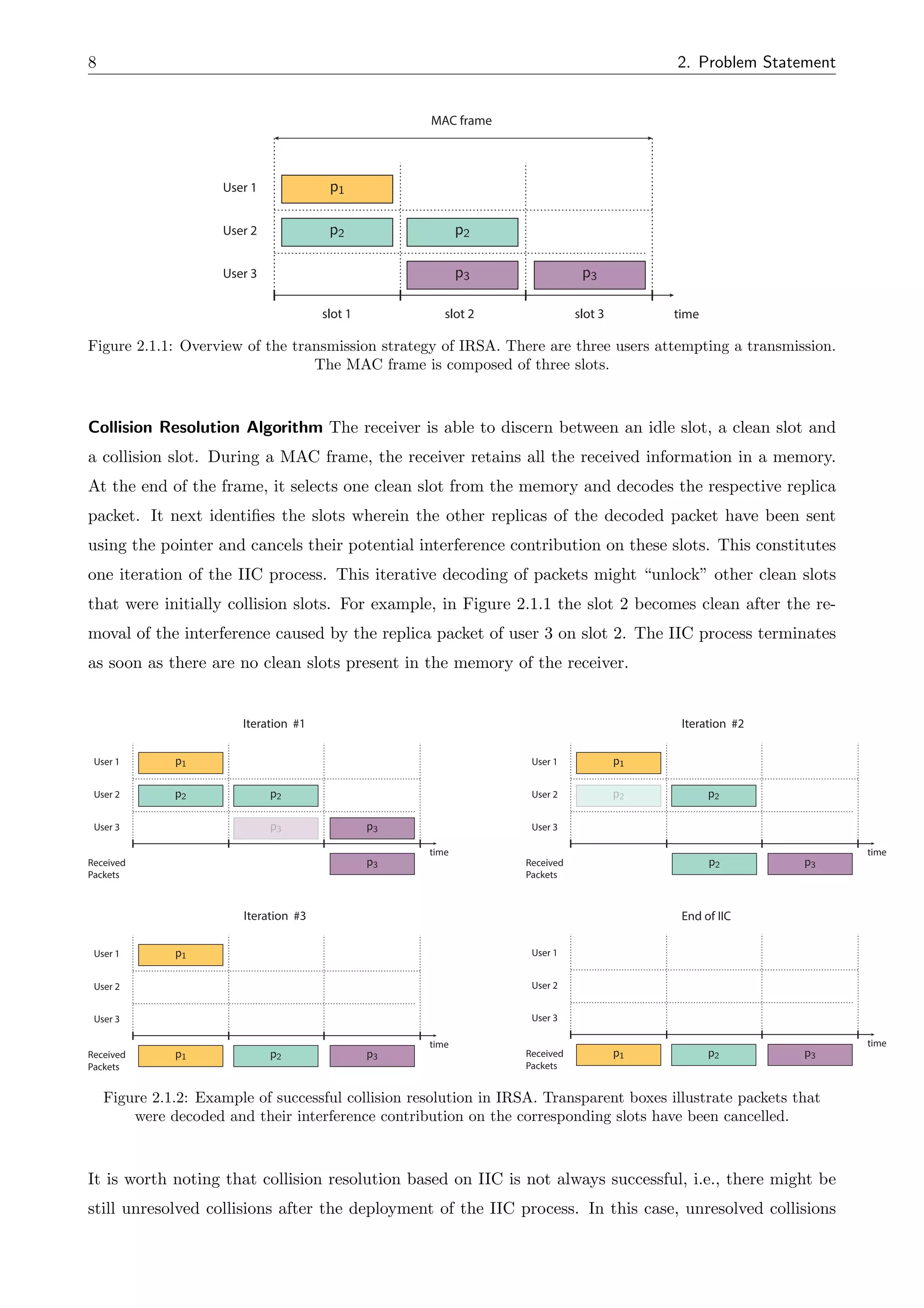
![2.2. Definitions and Conventions 9
are discharged by the receiver, resulting in the loss of the collided packets. Therefore, users involved
in unresolved collisions will experience a packet loss, e.g., user 1 and user 2 in Figure (2.1.3), and
will have to retransmit their lost packet in a subsequent MAC frame. In [10], a simple retransmission
policy is proposed in which users who do not receive an acknowledgment from the receiver retransmit
their packet in the next MAC frame.
Iteration #1
time
User 1
User 2
User 3 p3
Received
Packets
p1
p2 p2
p3
time
User 1
User 2
User 3
p1
p2 p2
p3 Received
Packets
p3
End of IIC
p1 p1
Figure 2.1.3: Example of unresolved collisions in IRSA. Transparent boxes illustrate packets that were
decoded and their interference contribution on the corresponding slots have been cancelled. The IIC process
terminates after one iteration; user1 and user 2 experience a packet loss.
Since there is the possibility of the IIC process failing to resolve completely the collisions occurred in
a MAC frame, the performance of the iterative decoder must be further examined, i.e., determine the
probability of a user experiencing a packet loss.
2.2 Definitions and Conventions
In this section, we provide a brief overview of the definitions and conventions used throughout the
thesis.
Conventions
1. We say that a user is unresolved when all the packet replicas he transmitted remain undecoded
at the end of the IIC process. Namely, unresolved users correspond to those who experienced a
packet loss due to unresolved collisions.
2. We say that a user is successfully decoded when at least one of the packet replicas he transmitted
has been decoded at the end of the IIC process. Namely, successfully decoded users correspond
to those who communicated their packet to the common receiver.
Definitions
1. Channel load G: the average number of users per slot.
2. Throughput T: the expected number of successfully decoded users per slot.
3. Packet loss probability PL: the probability of a user experiencing a packet loss.](https://image.slidesharecdn.com/finite-lengthperformanceanalysisofslottedaloha-thesis-220518201551-91ff873d/75/Finite-Length-Performance-Analysis-of-Slotted-ALOHA-Thesis-pdf-19-2048.jpg)
![10 2. Problem Statement
2.3 Problem Formulation
In this section, we review the asymptotic performance analysis of IRSA carried out by Liva in [10].
This will help us contrast our work from existing work as well formulate the problem examined in the
current thesis.
In [10], the following system model is considered: there are k users seeking to communicate a packet
to a common receiver, the MAC frame is composed of n slots and users’ repetition rates are drawn
from the probability distribution ⇤. Liva identified the similarities between the IIC process over a
MAC frame in IRSA and the iterative decoding process of codes on graphs. Towards this direction,
he conveniently represented users’ channel access by a bipartite graph and associated the IIC process
with an iterative decoding process over that graph. This enabled him to evaluate the evolution of the
average probability of a user experiencing a packet loss after i iterations of IIC using density evolution,
a technique commonly used in literature for the asymptotic analysis of LDPC codes. He then proved
that, in the limit of i, k, n ! 1, the IIC process will be successful, i.e., all collisions will be resolved,
with probability close to 1 as far as the o↵ered channel load G does not exceed a threshold value
denoted by G⇤(⇤). This result implies that if G G⇤(⇤), then all the transmitted packets will be
decoded by the receiver and hence the throughput T will be given by T = G; all the o↵ered channel
load is converted to useful traffic. Furthermore, the maximum achievable throughput is equal to G⇤.
Conversely, for channel loads G greater than the threshold G⇤(⇤), the IIC process will fail to resolve
all the collisions with probability bounded away from 0 and packet, resulting in non zero packet loss
probability. For a detailed overview of the density-based performance analysis of IRSA, we refer the
interested read to Appendix A.
time
User 1
User 2
User 3
p2
p2
p3 p3
slot 1 slot 2 slot 3
MAC frame
p1
(a) Transmission example.
User 1 User 2 User 3
slot 1 slot 2 slot 3
(b) Bipartite graph.
Figure 2.3.1: Graph representation of IRSA channel access.
Below, we provide several threshold values computed for di↵erent distributions. These distributions
are obtained in [10] by using numerical optimization methods such as di↵erential evolution [23].](https://image.slidesharecdn.com/finite-lengthperformanceanalysisofslottedaloha-thesis-220518201551-91ff873d/75/Finite-Length-Performance-Analysis-of-Slotted-ALOHA-Thesis-pdf-20-2048.jpg)
![2.3. Problem Formulation 11
Repetition rate distribution, ⇤(x) G⇤
0.5102x2 + 0.4898x4 0.868
00.5631x2 + 0.0436x3 + 0.3933x5 0.898
0.5465x2 + 0.1623x3 + 0.2912x6 0.915
0.5x2 + 0.28x3 + 0.22x8 0.938
0.4977x2 + 0.2207x3 + 0.0381x4 + 0.0756x5+
0.0398x6 + 0.0009x7 + 0.0088x8 + 0.0068x9+
0.0030x11 + 0.0429x14 + 0.0081x15 + 0.0576x16 0.965
Table 2.3.1: Thresholds computed for di↵erent distributions. Distributions are given in a polynomial
representation, with coefficient l of the term lxl
corresponding to the probability of a user sending l replicas.
The thresholding behavior of the scheme described above, i.e., all packets are decoded if channel load
G does not exceed G⇤, is valid though only under the theoretical regime of an infinitely long MAC
frame. Similarly to LDPC codes, the finite frame length regime gives rise to a non-zero packet loss
probability even for values of G less than the threshold G⇤, due to occurrence of stopping sets in the
associated bipartite graph [14]. This can be confirmed also through simulations.
0 0.1 0.2 0.3 0.4 0.5 0.6 0.7 0.8 0.9 1
10
−6
10
−5
10
−4
10
−3
10
−2
10
−1
10
0
Normalized Channel Load, G
MAC
Packet
Loss
Probability
IRSA − asymptotic analysis
IRSA − sim, N=100
IRSA − sim, N=200
IRSA − sim, N=1000
Figure 2.3.2: Packet loss probabilities for di↵erent MAC frame lengths, and for repetition rate distribution is
⇤(x) = 0.5x2
+ 0.28x3
+ 0.22x8
.
Since density evolution analysis does not enable us either to specify with accuracy or to upper bound
the PLR of the scheme, a finite-length analysis (i.e., k, n < 1) is needed. We are now ready to
formulate the problem of finite-length analysis.
Problem Statement. Given the number of users k, the MAC frame size n and the repetition rate
probability distribution ⇤, evaluate the probability PL(k, n, ⇤) of a user experiencing a packet loss.](https://image.slidesharecdn.com/finite-lengthperformanceanalysisofslottedaloha-thesis-220518201551-91ff873d/75/Finite-Length-Performance-Analysis-of-Slotted-ALOHA-Thesis-pdf-21-2048.jpg)

![Chapter 3
Finite-Length Performance Analysis
3.1 Introduction
Most of the works on IRSA schemes are concerned with the asymptotic case of infinitely long MAC
frames. This assumption ensures that the bipartite graph associated to a MAC frame realization does
not contain cycles and, in consequence, density evolution can be employed to analyze the performance
of the IIC process. However, the density evolution-based analysis provides an upper bound on the
achievable throughput and not exact results on the throughput and PLR of the scheme. In this section,
we provide an exact performance analysis of IRSA for a small number of users and small MAC frame
lengths. Henceforth, we will refer to this type of analysis as finite-length analysis.
3.2 System Model
We consider a fixed number of users communicating with a common receiver over a collision channel.
Similarly to [10], time is slotted and slots are organized into MAC frames, each composed of n slots.
Users are synchronized with the channel so that packet transmissions start only at the beginning of
slots.
time
MAC frame
time slot
MAC frame
Figure 3.2.1: Example of a MAC frame structure. Each frame is composed of 4 slots.
Users are characterized by sporadic activity. That is, only a subset of them has a packet to deliver
to the receiver at the beginning of each MAC frame. We will refer to these users as active and will
denote their number by the random variable K. In general, the statistic of K depends on the packet](https://image.slidesharecdn.com/finite-lengthperformanceanalysisofslottedaloha-thesis-220518201551-91ff873d/75/Finite-Length-Performance-Analysis-of-Slotted-ALOHA-Thesis-pdf-23-2048.jpg)
![14 3. Finite-Length Performance Analysis
arrival process at each user as well as on the backlogged users. For the purpose of our analysis, we
focus on a specific MAC frame wherein K takes a particular value, say K = k, 0 < k < n.
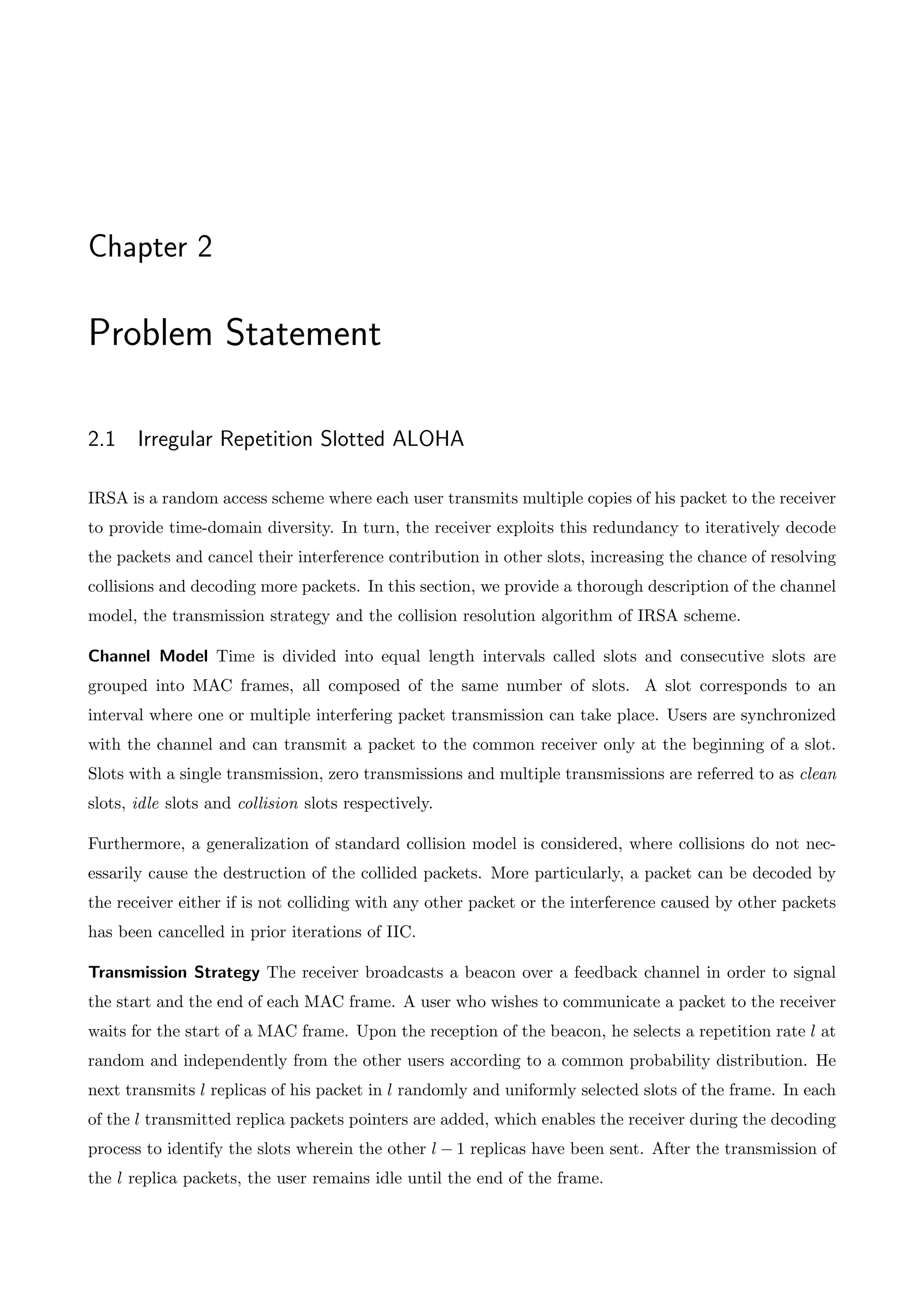
The k competing users transmit according to IRSA. Users’ repetition rates are drawn from the distri-
bution ⇤ = [⇤1, . . . , ⇤lmax ], where ⇤l, l 2 {1, . . . , lmax}, denotes the probability of a user transmitting
l packet replicas within a MAC frame and lmax denotes the maximum repetition rate allowed by the
scheme. As already known, collision resolution in IRSA relies primarily on IIC. This is possible due
to sophisticated physical layer techniques, which are beyond the scope of this work. However, we can
consider a collision channel model that is aware of this physical layer process. Next, we describe the
channel model considered in the subsequent analysis.
Collision channel model
1. A packet transmitted in a collision-free slot is always decoded by the receiver.
2. If multiple packets, say p1, . . . , pm, m 2, are transmitted in a slot, the receiver then “sees” the
composite signal p1 · · · pm. The operation “ ” is called summation and has the following
properties:
(a) If m 2, then p1 · · · pm is di↵erent than any valid packet. That means that the receiver
can discriminate between a slot with a singe packet (clean slot), a slot with zero packets
(idle slot) and a slot with at least two packets (collision slot).
(b) If the receiver knows the signal p1 · · · pm in a slot and has already decoded one of these
packets, say packet p1, then it can derive the signal p2 · · · pm.
Under this collision channel model, IIC is feasible. According to assumption (2b), a packet involved in
a collision can be decoded when all the other packets participating in the collision have been decoded
in prior iterations of the IIC process.
3.3 Characterization of Packet Loss Probability
Due to the symmetry of the problem, i.e, all users transmit according to the same repetition rate
distribution, each user has the same probability of experiencing a packet loss. Therefore, the packet
loss probability can be evaluated by determining the expected fraction of unresolved users. Towards
this direction, let us denote the random variable “number of unresolved users given that k users trans-
mitted over n slots according to the repetition rate distribution ⇤” by U | k, n; ⇤. It is easy to see
that U | k, n; ⇤ takes values in {1, . . . , k} and Pr (U = 1 | k, n; ⇤) = 0 since more than one users are
needed for having a collision. We now express the PLR as
PL (k, n, ⇤) =
E [U | k, n; ⇤]
k
=
k
X
u=2
u
k
Pr (U = u | k, n; ⇤) (3.3.1)](https://image.slidesharecdn.com/finite-lengthperformanceanalysisofslottedaloha-thesis-220518201551-91ff873d/75/Finite-Length-Performance-Analysis-of-Slotted-ALOHA-Thesis-pdf-24-2048.jpg)
![3.4. Matrix-Based Analysis 15
We incorporate the repetition rate of each user into the computation of the packet loss probability
as follows: Let D = [D1, . . . , Dk], Di 2 {1, . . . , lmax} denote the (random) vector whose elements cor-
respond to the repetition rates of the users, i.e., D1 corresponds to the repetition rate of user 1, D2
corresponds to the repetition rate of user 2, and so forth. Since users select their repetition rates inde-
pendently from each other and following the same distribution ⇤, the probability that they adopted
repetition rates described by the vector d = [d1, . . . , dk] is given by
Pr (D = d) =
k
Y
i=1
Pr (Di = di) =
k
Y
i=1
⇤di
Let D be the set of all the possible repetition rate vectors d allowed by the distribution ⇤, i.e,
D =
n
d 2 {1, . . . , lmax}k
: Pr (D = d) > 0
o
. Summing over D, we take
PL (k, n, ⇤) =
X
d2D
k
X
u=2
u
k
Pr (U = u | k, n, D = d) Pr (D = d)
=
X
d2D
k
X
u=2
u
k
Pr (U = u | k, n, D = d)
k
Y
i=1
⇤di
(3.3.2)
where the decoding failure probability Pr (U = u | k, n, D = d) is the probability of having u unre-
solved users, given that k users transmitted a packet, the MAC frame is composod of n slots and
users’ repetition rates are specified by the vector d. Once we know PL (k, n, ⇤), we can also determine
the throughput T of the scheme using the relationship
T = G(1 PL)
In either case, the challenging part is the evaluation of the decoding failure probability. We tackle
this mathematical challenge by interpreting our random access problem into a matrix occupancy
problem [19].
3.4 Matrix-Based Analysis
3.4.1 Relation Between IRSA and Matrix Occupancy Problems
Occupancy or balls-into-bins problems have a long history since they can be used to translate realistic
problems into mathematical ones in a natural way. In a typical occupancy problem, a set of balls
is randomly assigned into a group of bins. The main objective then is to determine the probability
of basic outcomes such as the number of empty bins, the number of bins that contain at least one
ball, etc. It is easy to see that a random access problem can be viewed as an occupancy problem by](https://image.slidesharecdn.com/finite-lengthperformanceanalysisofslottedaloha-thesis-220518201551-91ff873d/75/Finite-Length-Performance-Analysis-of-Slotted-ALOHA-Thesis-pdf-25-2048.jpg)
![16 3. Finite-Length Performance Analysis
considering packets and slots as balls and bins respectively. Many works in the literature have already
used the results of occupancy problems to derive an exact performance analysis for SA and SA with
capture e↵ect [21], [22]. The question that arises is if we can exploit these studies to derive an exact
analysis for IRSA scheme. The answer is not completely, because the performance of the IIC process
in IRSA cannot be fully analyzed by the original balls-into-bins problem used in SA. However, we can
get the intuition and follow a similar approach.
3.4.2 Preliminaries
For the sake of the finite-length analysis, we first introduce a novel matrix representation of the IIC
process. We keep on considering a MAC frame composed of n slots, in which k users attempt a packet
transmission. One realization of the MAC frame status, i.e., the slots in which each user transmitted
his packet replicas, can be conveniently described by a k ⇥ n binary matrix M = (mij), with rows and
columns corresponding to users and slots respectively and with each entry being one or zero according
to the rule
mij =
⇢
1, if the i-th user sent a burst in the j-th slot
0, otherwise
Since matrix M specifies the transmission slots of each user, we will refer to it as transmission ma-
trix. By definition, the columns of the transmission matrix, mj = [mij]1ik, j = 1, . . . , n, are
binary vectors that take value in {0, 1}k
. The weight of a column mj, denoted w(mj), is defined as
w(mj) =
Pk
i=1 mij. Since w(mj) equals the number of ones that are present in column mj, it gives
the number of packet replicas sent in slot j. Thus, columns with weight one, e.g., [01000]T , represent
clean slots whereas columns with weight greater than one, e.g., [01110]T , represent collision slots.
M =
0
B
B
@
1 1 0 1
0 1 0 1
0 1 0 1
0 0 1 1
1
C
C
A
Transmission example Matrix-based representaition
time
User 1
User 2
User 3 p3
slot 1 slot 2 slot 3
MAC frame
p1 p1 p1
p2
p2
p3
p4 p4
User 4
slot 4
Figure 3.4.1: Matrix representation of IRSA channel access.
Exploiting the matrix representation of IRSA channel access, we can relate the IIC process over a MAC](https://image.slidesharecdn.com/finite-lengthperformanceanalysisofslottedaloha-thesis-220518201551-91ff873d/75/Finite-Length-Performance-Analysis-of-Slotted-ALOHA-Thesis-pdf-26-2048.jpg)
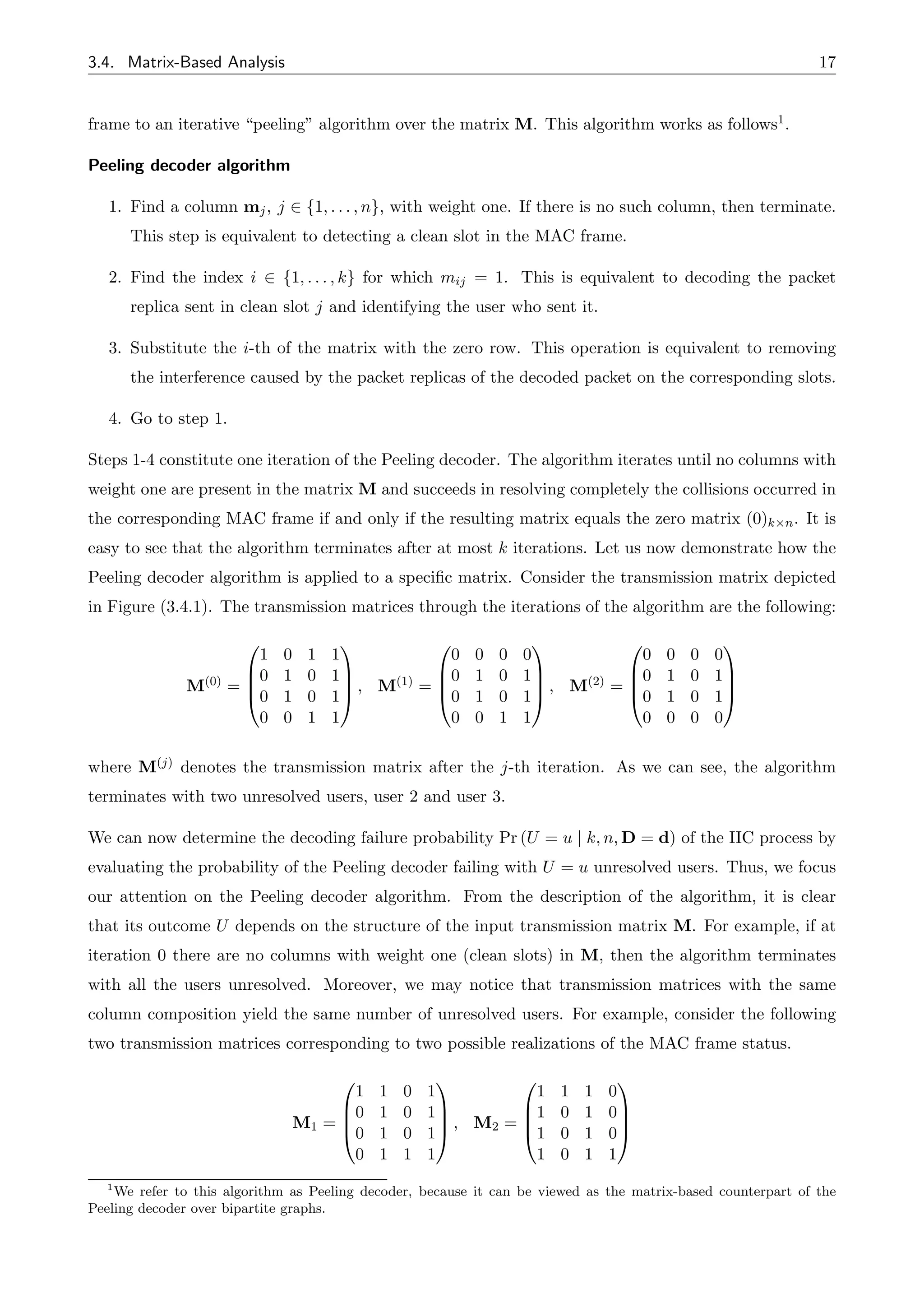
![18 3. Finite-Length Performance Analysis
These matrices seem to be di↵erent, however they share the same column composition, which is
specified by the multiset2
[1000]T
, [1111]T
, [1111]T
, [0001]T
By applying the Peeling decoder algorithm to each matrix, we take (after two iterations)
M
(2)
1 =
0
B
B
@
0 0 0 0
0 1 0 1
0 1 0 1
0 0 0 0
1
C
C
A , M
(2)
2 =
0
B
B
@
0 0 0 0
1 0 1 0
1 0 1 0
0 0 0 0
1
C
C
A
confirming our initial assertion that the Peeling decoder algorithm gives the same number of unresolved
users when it is applied to matrices with the same column composition — in the previous example,
the Peeling decoder terminated with two unresolved users in both cases.
It turns out that the information about the exact structure of the transmission matrix is not needed
for the evaluation of the error probability of the Peeling decoder. In fact, what is needed is the infor-
mation about the column composition of the transmission matrix. We formulate this observation in
the following proposition.
Proposition. The knowledge of the column composition of the transmission matrix suffices for the
evaluation of the outcome U of the Peeling decoder algorithm.
The key result of the above proposition is that we can evaluate the probability of the decoder fail-
ing to resolve all the collisions by marginalizing over the distribution of the column configuration of
the transmission matrix, i.e., by computing for each possible column configuration the probability of
the decoder terminating with u unresolved users. Towards this direction, we introduce the notion of
occupancy vector, a vector that shows how many times each type of column is present in a matrix.
Let Ck be the set of the column vectors that take value in {0, 1}k. The occupancy vector of a given
matrix A 2 {0, 1}k⇥n then is defined as the vector n(A) = [nc]c2Ck
whose elements nc correspond to
the number of columns in A that are equal to the vector c. For example, consider the following matrix:
A =
✓
0 1
1 1
◆
In this case, the set C2 of the column vectors that take value in {0, 1}2 is
C2 = {[00]T
, [01]T
, [10]T
, [11]T
}
and the occupancy vector of matrix A is
2
A multiset is a generalization of a set that allows multiple instances of its elements.](https://image.slidesharecdn.com/finite-lengthperformanceanalysisofslottedaloha-thesis-220518201551-91ff873d/75/Finite-Length-Performance-Analysis-of-Slotted-ALOHA-Thesis-pdf-28-2048.jpg)
![3.4. Matrix-Based Analysis 19
n(A) =
h
n[00]T = 0, n[01]T = 1, n[10]T = 0, n[11]T = 1
i
By definition, the transmission matrix is a random matrix. Hence, we will denote its associated occu-
pancy vector by the random variable N(M), whereas one instance of it by n. Let N = {n = [nc]c2Ck
:
0 nc n, 8c 2 Ck} be the set of all the possible instances of N(M). Using the notion of occupancy
vector, we now express the decoding failure probability Pr (U = u | k, n, D = d) as
Pr (U = u | k, n, D = d) =
X
n2N
Pr (U = u, N(M) = n | k, n, D = d)
=
X
n2N
Pr (U = u | k, n, D = d, N(M) = n) Pr (N(M) = n | k, n, D = d)
(3.4.1)
where
– Pr (N(M) = n | k, n, D = d) corresponds to the probability of experiencing a transmission ma-
trix M with occupancy vector n, given that k users transmitted a packet over a MAC frame of
n slots following the repetition rate vector d.
– Pr (U = u | k, n, D = d, N(M) = n) corresponds to the probability of the Peeling decoder algo-
rithm terminating with u unresolved users, given the occupancy vector n of the transmission
matrix, the number of users k, the MAC frame size n and the repetition rate vector d.
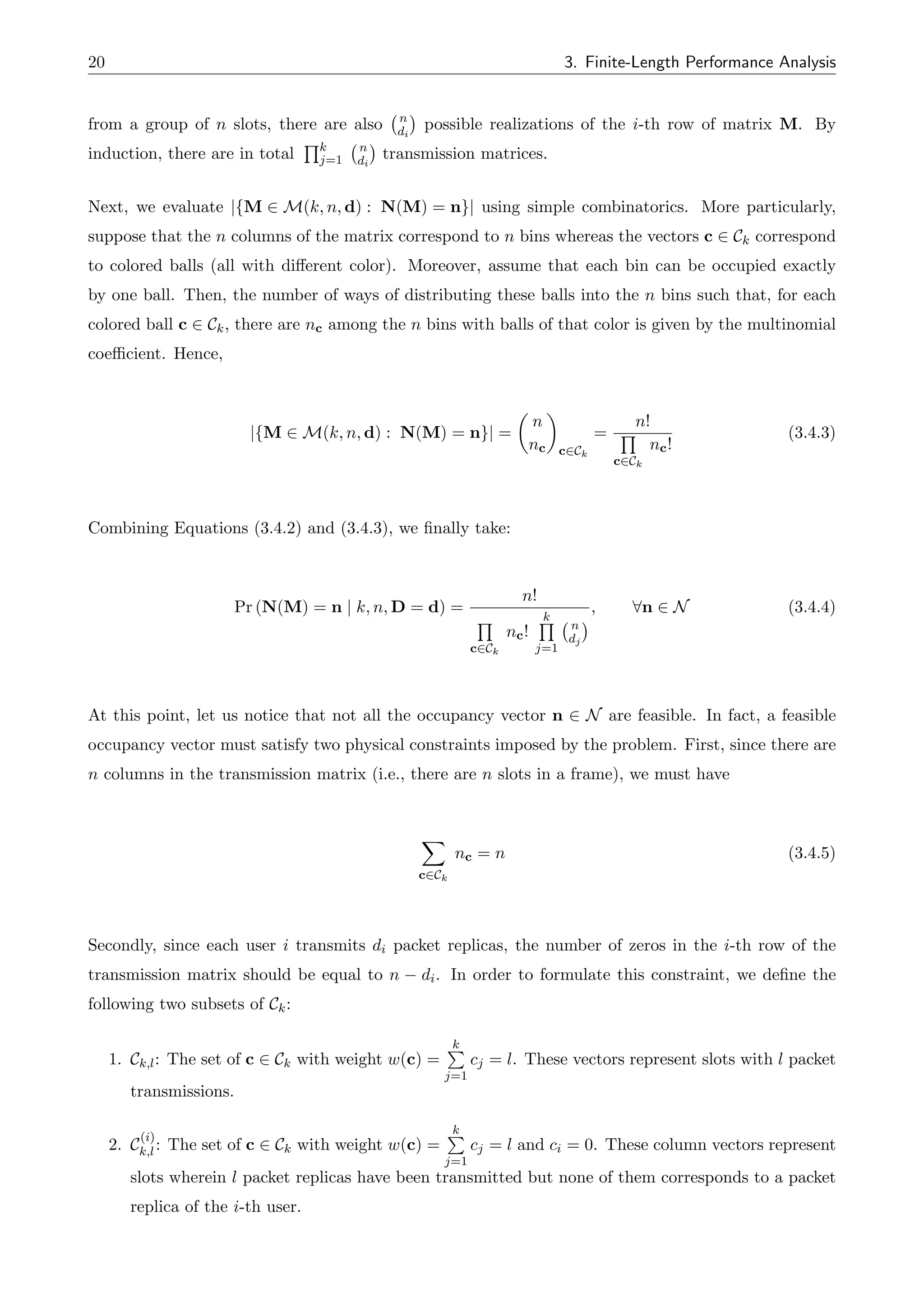
3.4.3 Probability Distribution of Occupancy Vector
As already known, users select uniformly and independently from each other their transmission slots.
This means that each instance of the transmission matrix is equally possible to be experienced for
given k, n and d and, in consequence, we can evaluate the probability Pr (N(M) = n | k, n, D = d) as
Pr (N(M) = n | k, n, D = d) =
number of transmission matrices with occupancy vector n
total number of transmission matrices
=
|{M 2 M(k, n, d) : N(M) = n}|
|M(k, n, d)|
(3.4.2)
where M(k, n, d) denotes the set of all the admissible transmission matrices for given k, n and d, i.e.,
M(k, n, d) = {M 2 {0, 1}k⇥n :
Pn
j=1 mij = di, 8i = 1, . . . , k}.
We compute |M(k, n, d)| as follows. Recall that each user i, i 2 {1, . . . , k}, accesses the channel by
selecting di slots among the n slots of the MAC frame. Since there are n
di
ways of choosing di slots](https://image.slidesharecdn.com/finite-lengthperformanceanalysisofslottedaloha-thesis-220518201551-91ff873d/75/Finite-Length-Performance-Analysis-of-Slotted-ALOHA-Thesis-pdf-29-2048.jpg)
![3.4. Matrix-Based Analysis 21
The second constraint is given by
k
P
l=1
P
c2C
(1)
k,l
nc = n d1
k
P
l=1
P
c2C
(2)
k,l
nc = n d2
.
.
.
k
P
l=1
P
c2C
(k)
k,l
nc = n dk
(3.4.6)
Henceforth, we will denote the set of all the feasible occupancy vectors for given k, n and d by
N(k, n, d). If n 62 N(k, n, d), we set Pr (N(M) = n | k, n, D = d) = 0.
3.4.4 Decoding Failure Probability
In the previous subsection, we determined the probability of having a transmission matrix of a specific
occupancy vector at the beginning of the Peeling decoder algorithm, i.e., 0-th iteration. For the pur-
pose of our analysis, we introduce the notation M(j) and nj = [n
(j)
c ]c2Ck
for denoting the transmission
matrix and the associated occupancy vector at the end of the j-th iteration of the Peeling decoder.
Combing now Equations (3.4.4) and (3.4.1), we take
Pr (U = u | k, n, D = d) =
X
n02N
Pr
⇣
U = u | k, n, D = d, N(M(0)
) = n0
⌘
Pr
⇣
N(M(0)
) = n0 | k, n, D = d
⌘
(3.4.7)
=
X
n02N(k,n,d)
Pr
⇣
U = u | k, n, D = d, N(M(0)
) = n0
⌘ n!
Q
c2Ck
n
(0)
c !
k
Q
j=1
n
dj
(3.4.8)
where we substituted M and n with M(0) and n0 respectively to indicate that these probabilities are
referred to the beginning of the iterative decoding process.
As we may notice, the probability Pr U = u | k, n, D = d, N(M(0)) = n0 is either one or zero, de-
pending on whether the event “the Peeling decoder starting with a transmission matrix of occupancy
vector n0 will terminate with u unresolved users” is true or false respectively. Therefore, we can
substitute it with a function Q(·) that implements the following rule:
Q(k, u, n0) =
⇢
1, if Pr U = u | k, n, D = d, N(M(0)) = n0 = 1
0, if Pr U = u | k, n, D = d, N(M(0)) = n0 = 0
(3.4.9)
We now rewrite Equation (3.4.7) as](https://image.slidesharecdn.com/finite-lengthperformanceanalysisofslottedaloha-thesis-220518201551-91ff873d/75/Finite-Length-Performance-Analysis-of-Slotted-ALOHA-Thesis-pdf-31-2048.jpg)
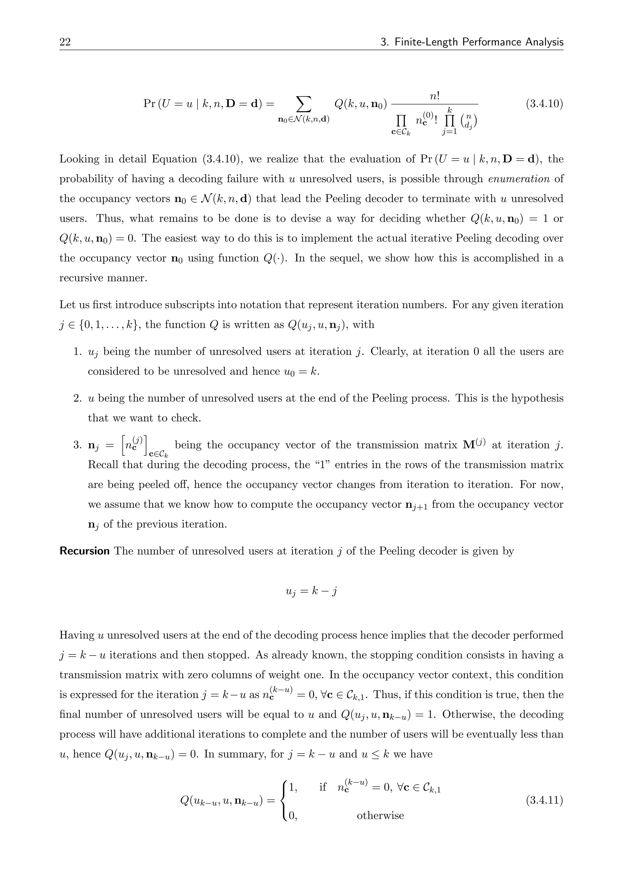
![3.4. Matrix-Based Analysis 23
Next, we examine the case where the decoding process is ongoing but has not completed k u itera-
tions yet, i..e, j k u 1. At this point, the number of the current unresolved users is
uj = k j k (k u 1) = u + 1
Again, we apply the stopping condition to the occupancy vector nj. If n
(j)
c = 0, 8c 2 Ck,1, then
the decoding process terminates and the number of unresolved users is greater than u, hence we set
Q(uj, u, nj) = 0. In the opposite case, the decoding process can proceed with the next iteration j + 1
and hence we set Q(uj, u, nj) = Q(uj+1, u, nj+1) = Q(uj 1, u, nj+1). In summary, for j k u 1
and u k 1, we have
Q(uj, u, nj) =
8
<
:
Q(uj 1, u, nj+1), if 9 c 2 Ck,1 : n
(j)
c > 0,
0, otherwise
(3.4.12)
Tracking the evolution of occupancy vector For the recursive evaluation of the function Q(·), we
assumed that we are able to track the evolution of occupancy vector nj through the iterations of
the decoding process. We next show how this is accomplished. Consider that the Peeling decoder
algorithm goes from iteration j to iteration j + 1. During this transition, the “1” elements of the
row corresponding to the decoded user of the transmission matrix M(j) are peeled o↵. This results
in a new transmission matrix M(j+1) and hence a new occupancy vector nj+1. We evaluate the oc-
cupancy vector nj+1 using the occupancy vector nj of the previous iteration as follows. Assume that
user i 2 {1, . . . , k} is decoded at iteration j. Then, we can model the peeling operation during the
transition j ! j + 1 using the following mapping: for x = [x1, . . . , xk] 2 Ck ,
F(i, x) = F (i, [x1, . . . , xi 1, xi, xi+1, . . . , xk]) = [x1, . . . , xi 1, 0, xi+1, . . . , xk] = x̂
where mapping F is applied to each column of matrix M(j). Let us also define the inverse image of x̂
as following:
F 1
(i, x̂) = F 1
(i, [x1, . . . , xi 1, 0, xi+1, . . . , xk]) = {x 2 Ck : F(i, x) = [x1, . . . , xi 1, 0, xi+1, . . . , xk]}
= {[x1, . . . , xi 1, 0, xi+1, . . . , xk], [x1, . . . , xi 1, 1, xi+1, . . . , xk]}
Now, we can evaluate nj+1 from nj using the following formula:](https://image.slidesharecdn.com/finite-lengthperformanceanalysisofslottedaloha-thesis-220518201551-91ff873d/75/Finite-Length-Performance-Analysis-of-Slotted-ALOHA-Thesis-pdf-33-2048.jpg)
![24 3. Finite-Length Performance Analysis
nj+1 =
h
n
(j+1)
ĉ
i
ĉ2Ck
: n
(j+1)
ĉ =
X
c2F 1(i,ĉ)
n
(j)
c (3.4.13)
where F 1(i, ĉ) = {c 2 Ck : F(i, c) = ĉ} is the inverse image of ĉ. Next, we give an example to
demonstrate how the occupancy vector can computed through the iterations of the Peeling decoding
process using Equation (3.4.13).
Example. (Computation of occupancy vector after one decoding step) Suppose that the Peeling de-
coder algorithm is at iteration j and the transmission matrix M(j) is
M(j)
=
0
@
0 0 1 1 1
0 1 0 0 1
0 1 0 1 1
1
A
The associated occupancy vector then is given by
nj =
h
n
(j)
[000]T = 1, n
(j)
[001]T = 0, n
(j)
[010]T = 0, n
(j)
[011]T = 1, n
(j)
[100]T = 1, n
(j)
[101]T = 1, n
(j)
[110]T = 0, n
(j)
[110]T = 1
i
The Peeling decoder decodes user 1 and goes from iteration j to iteration j + 1. The new occupancy
vector nj+1 =
h
n
(j+1)
ĉ
i
ĉ2C3
is computed using Equation (3.4.13) as following:
n
(j+1)
[000]T = n
(j)
[000]T + n
(j)
[100]T = 1 + 1 = 2
n
(j+1)
[001]T = n
(j)
[001]T + n
(j)
[101]T = 0 + 1 = 1
n
(j+1)
[010]T = n
(j)
[010]T + n
(j)
[110]T = 0 + 0 = 2
n
(j+1)
[011]T = n
(j)
[011]T + n
(j)
[111]T = 1 + 1 = 2
n
(j+1)
[100]T = n
(j+1)
[101]T = n
(j+1)
[110]T = n
(j+1)
[111]T = 0
We next confirm that nj+1 was computed correctly by applying the mapping F to matrix M(j) and
then comparing the occupancy vector of the resulting matrix M(j+1) with the vector nj+1. Applying
the mapping F to M(j) we take
M(j) =
0
@
0 0 1 1 1
0 1 0 0 1
0 1 0 1 1
1
A F(1,·)
! M(j+1) =
0
@
0 0 0 0 0
0 1 0 0 1
0 1 0 1 1
1
A
and indeed the occupancy vector of matrix M(j+1) coincides with the vector computed above.](https://image.slidesharecdn.com/finite-lengthperformanceanalysisofslottedaloha-thesis-220518201551-91ff873d/75/Finite-Length-Performance-Analysis-of-Slotted-ALOHA-Thesis-pdf-34-2048.jpg)
![3.5. Packet Loss Probability 25
3.5 Packet Loss Probability
In the current section, we provide an expression for the exact evaluation of the packet loss probability
of IRSA, given the number of users k, the MAC frame length n and the repetition rate probability
distribution ⇤. More particularly, combining Equations (3.3.2) and (3.4.10) we take
PL (k, n, ⇤) =
1
k
X
d2D
k
X
u=2
X
n02N(k,n,d)
u Q(k, u, n0)
n!
Q
c2Ck
n
(0)
c !
k
Q
j=1
n
dj
k
Y
i=1
⇤di
(3.5.1)
where the value of Q(k, u, n0) 2 {0, 1} is computed using (3.4.12), (3.4.11) and (3.4.13), and n0 =
[n
(0)
c ]c2Ck
denotes the occupancy vector at the beginning of the decoding process. Let us note that the
enumeration of occupancy vectors, i.,e the sum over all the admissible occupancy vectors, results in
an exponential computational complexity. Hence the application of Equation (3.5.1) is limited only
to small systems with few users and short MAC frame lengths.](https://image.slidesharecdn.com/finite-lengthperformanceanalysisofslottedaloha-thesis-220518201551-91ff873d/75/Finite-Length-Performance-Analysis-of-Slotted-ALOHA-Thesis-pdf-35-2048.jpg)

![Chapter 4
Simulation Results
4.1 Introduction
We conducted simulations to evaluate the validity of the proposed matrix-based analysis for the
performance evaluation of IRSA. In the following, we summarize the simulation input parameters, as
well as we briefly describe the simulation procedure.
1. k: number of users transmitting within a MAC frame
2. n: number of slots per MAC frame
3. ⇤ = [L1, . . . , Llmax ]: the repetition rate probability distribution. For ease of notation, we adopt
the polynomial representation ⇤(x) = L1x + L2x2 + · · · + Llmax xlmax for the distribution ⇤.
For each simulated scenario, we first compute the probability Pr (U = u | k, n; ⇤) using Equation
(3.4.10). We then simulate the actual transmission and collision resolution algorithm of IRSA for
1000 times and evaluate the respective failing decoding probability. This is done as follows: let ui
denote the number of unresolved users obtained in the i-th simulation run. The decoding failure
probability Pr (U = u | k, n; ⇤) is then computed as (Equation (3.3.1))
Pr (U = u | k, n; ⇤) =
E [U | k, n; ⇤]
k
⇡
P1000
i=1 ui
1000k
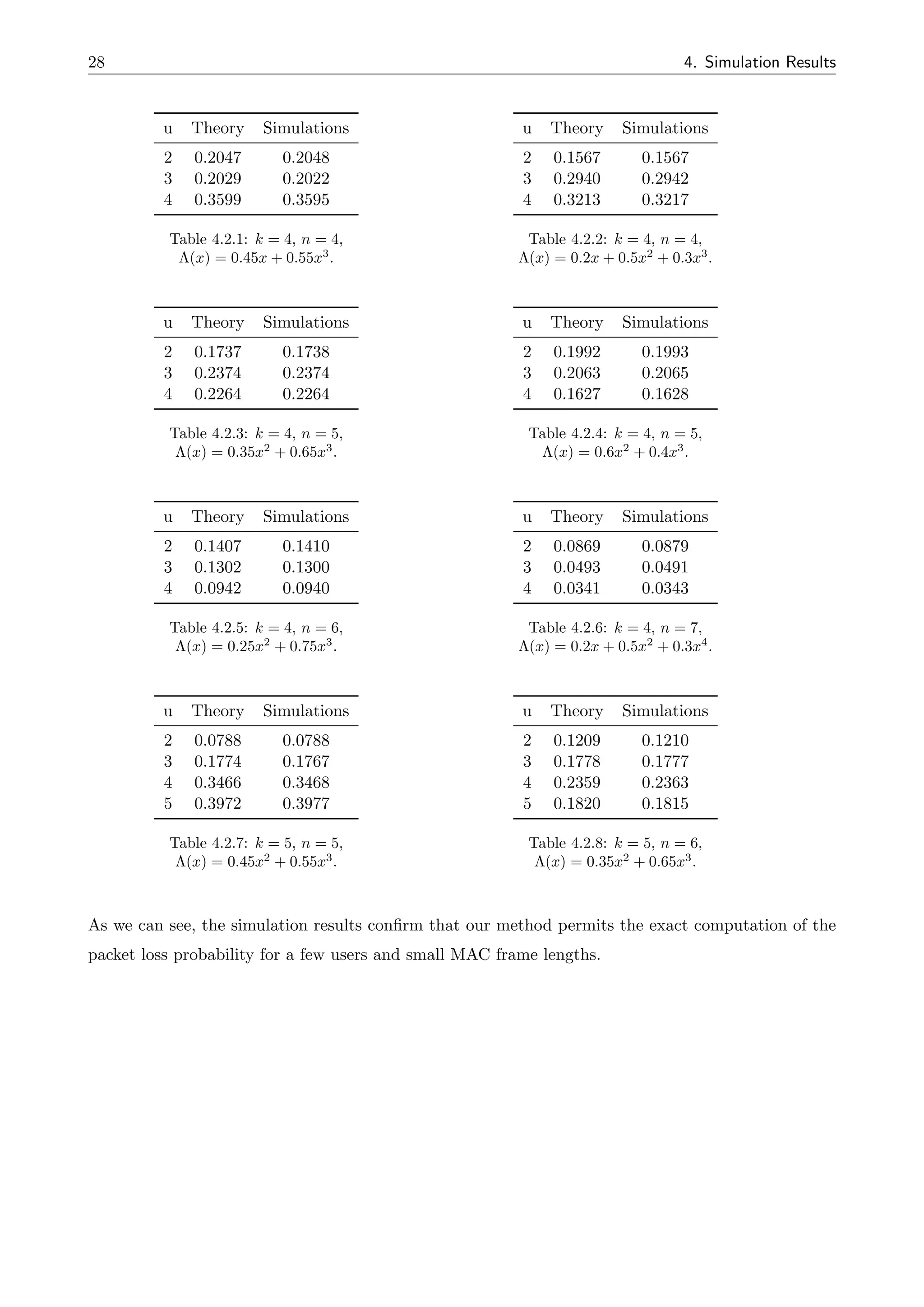
4.2 Results
In this section, we present simulation results for di↵erent system setups. Due to the high computational
complexity of the proposed analysis, we tested our method only for small systems, with the maximum
number of users and slots per MAC frame being limited to 5 and 6 respectively.](https://image.slidesharecdn.com/finite-lengthperformanceanalysisofslottedaloha-thesis-220518201551-91ff873d/75/Finite-Length-Performance-Analysis-of-Slotted-ALOHA-Thesis-pdf-37-2048.jpg)
![Chapter 5
Conclusions
During this thesis, our major concern has been to improve the existing performance analysis tech-
niques for IRSA scheme. In more detail, we established a key connection between IRSA and matrix
occupancy problems. Exploiting this analogy, we developed a performance analysis that enables
the exact computation of the packet loss probability of the scheme. Our approach though relies on
combinatorial enumeration, which results in exponential computational complexity. Therefore, the
proposed performance analysis is applicable only to small systems with few users and short MAC
frame lengths.
A first direction for research would be to study the asymptotic behavior of the derived expressions,
with the hope to find a more accurate asymptotic expressions than the ones provided by density
evolution. A good start for this would be the work on the asymptotic distributions of matrix occupancy
problems [19].
An additional direction for future work would be the improvement of the derived analysis by attempting
to reduce its high computation complexity. A good start towards this might be the work of Ephremides
on the finite-length analysis of slotted ALOHA with capture [22].](https://image.slidesharecdn.com/finite-lengthperformanceanalysisofslottedaloha-thesis-220518201551-91ff873d/75/Finite-Length-Performance-Analysis-of-Slotted-ALOHA-Thesis-pdf-39-2048.jpg)

![Bibliography
[1] N. Abramson, “The ALOHA system-another alternative for computer communications,” in Proc.
1970 Fall Joint Comput. Conf., vol. 37, pp. 281-285.
[2] L. G. Roberts, “ALOHA packet systems with and without slots and capture,” ARPANET system
Note 8 (NIC11290), June 1972.
[3] O. G. Gabbard and P. Kaul, “Time-division multiple access,” in IEEE Electronics and Aerospace
Systems Conv. (EASCON), pp. 179-184, Oct. 1974.
[4] J. L. Dicks and M. P. Brown, Jr., “Frequency division multiple access (FDMA) for satellite
communication systems,” in IEEE Electronics and Aerospace Systems Conv. (EASCON), pp.
167-178, Oct. 1974.
[5] S. Verdu, Multiuser Detection. Cambridge University Press, 1998.
[6] P. Patel and J. Holtzman, “Analysis of a simple successive interference cancellation scheme in
DS/CDMA system,” Selected Areas in Communications, IEEE Journal on, vol. 12, no. 5, pp.
796-807, 1994.
[7] J. Capetanakis, “Tree algorithms for packet broadcast channels,” IEEE Trans. Inf. Theory, vol.
25, no. 5, pp. 505-515, Sep. 1979.
[8] S. S. Lam, “A carrier sense multiple access protocol for local networks,” Computer Networks, vol.
4, no. 1, pp. 21-32, 1980.
[9] E. Casini, R. De Gaudenzi, and O. Herrero, “Contention resolution diversity slotted ALOHA
(CRDSA): An enhanced random access scheme for satellite access packet networks,” IEEE Trans.
on Wireless Commun., vol. 6, no. 4, pp. 1408-1419, 2007.
[10] G. Liva, “Graph-based analysis and optimization of contention resolution diversity slotted
ALOHA,” IEEE Trans. Commun., vol. 59, no. 2, pp. 477-487, 2011.
[11] R. G. Gallager, Low-Density Parity-Check Codes. Cambridge, MA: M.I.T. Press, 1963.](https://image.slidesharecdn.com/finite-lengthperformanceanalysisofslottedaloha-thesis-220518201551-91ff873d/75/Finite-Length-Performance-Analysis-of-Slotted-ALOHA-Thesis-pdf-41-2048.jpg)
![32 Bibliography
[12] M. Luby, M. Mitzenmacher, A. Shokrollahi, and D. A. Spielman, “Imporived low-density parity-
check codes using irregular graphs,” IEEE Trans. Inf. Theory, vol. 47, no. 2, pp. 585-598, Feb.
2001.
[13] T. Richardson and R. Urbanke, “The capacity of low-density parity-check codes under message-
passing decoding,” IEEE Trans. Inf. Theory, vol. 47, no. 2, pp. 599-618, Feb. 2001.
[14] C. Di. D. Proietti, I. E. Telatar, T. J. Richardson, and R. L. Urbanke, “Finite-length analysis of
low-density parity-check codes on the binary erasure channel,” IEEE Trans. Inf. Theory, vol. 48,
no. 6, pp. 1459-1473, June 2002.
[15] E. Paolini, G. Liva, and M. Chiani, “Coded slotted ALOHA: A graph-based method for uncoor-
dinated multiple access,” ArXiv, vol. /1401.1626, 2014.
[16] C. Stefanovic, P. Popovski, and D. Vukobratovic, “Frameless ALOHA protocol for wireless net-
works,” IEEE Commun. Lett., vol. 16, no. 12, pp. 2087-2090, 2012.
[17] C. Stefanovic and P. Popovski, “Aloha random access that operates as a rateless code,” IEEE
Trans. Commun., vol. 61, no. 11, pp. 4653-4662, November 2013.
[18] M. Ghanbarinejad and C. Schlegel, “Irregular repetition slotted ALOHA with multiuser detec-
tion,” in Proc. the 10th Annual Conf. Wireless On-demand Netw. Syst. Services, Ban↵, AB, Mar.
2013, pp. 201-205.
[19] P. J. Eicker, M. M. Siddiqui, and J. Mielke, Paul W., “A matrix occupancy problem,” The Annals
of Mathematical Statistics, vol. 43, no. 3, pp. pp. 988-996, 1972.
[20] C. Berge, Principles of Combinatorics. New Work: Academic, 1971.
[21] J. E. Wieselthier and A. Ephremides, “A combinatorial technique for the analysis of the framed
contention-based multiple access protocols,” presented at 18th Annu. Conf. Inform. Sci. Syst.,
Princeton Univ., March 1984.
[22] J. E. Wieselthier and A. Ephremides, “An exact analysis and performance evaluation of framed
ALOHA with capture,” Naval Res. Lab. Memo. Rep. 6056, Sept. 1987.
[23] R. Storn and K. Price, “Di↵erential evolution - a simple and efficient heuristic for global opti-
mization over continuous spaces,” J. Global Optimization, vol. 11, no. 4, pp. 341-359, Dec. 1997.](https://image.slidesharecdn.com/finite-lengthperformanceanalysisofslottedaloha-thesis-220518201551-91ff873d/75/Finite-Length-Performance-Analysis-of-Slotted-ALOHA-Thesis-pdf-42-2048.jpg)
![Appendix B
Implementation of the Interference Cancellation
Mechanism
In this appendix, we address the actual implementation of the interference cancellation (IC) operation.
Let us consider the case where l users attempt a transmission within the same slot. We stick to the
case of perfect power control and equal channel conditions (gain) among the users. We denote by
u(i)(t) the complex baseband pulse amplitude modulation (PAM) signal transmitted by the i-th user,
i.e.,
u(i)
(t) =
ns
X
k=1
b
(i)
k (t kTs)
where ns is the number of symbols and Ts is the symbol period. By (t) = F 1
np
CR(f)
o
we denote
the pulse shape, with CR(f) being the frequency response of the raised-cosine filter.
Each contribution is received with a random delay ✏i, a random frequency o↵set fi ⇠ U[ fmax, fmax]
and a random phase o↵set 'i ⇠ U[0, 2⇡)1. The received signal after the matched filter (MF) is given
by
r(t) =
l
X
i=1
z(i)
(t) ⇤ h(t) + n(t)
where n(t) is the Gaussian noise contribution, h(t) = ⇤( t) is the MF impulse response and z(i)(t) =
Pns
k=1 b
(i)
k (t kTs ✏i)exp(j2⇡fit + j'i). Assuming frequency shifts that are small with respect to
the signal bandwidth (i.e, fmaxTs << 1), the received signal can be approximated by
r(t) '
l
X
i=1
ũ(i)
(t ✏i)ej2⇡fit+j'i
+ n(t) (B.0.1)
Here, ũ(i)(t) is the response of the MF to u(i)(t). We assume next that the contribution to be recovered
is the one for i = 1, and the residual l 1 contributions ũ(2)(t), ũ(3)(t), . . . , ũ(l)(t) represent the
interference to be cancelled. We consider moreover that the l 1 interfering signals correspond to
di↵erent packet replicas that have been correctly decoded in other slots.
1
U[a, b] denotes the uniform distribution over the closed interval [a, b].](https://image.slidesharecdn.com/finite-lengthperformanceanalysisofslottedaloha-thesis-220518201551-91ff873d/75/Finite-Length-Performance-Analysis-of-Slotted-ALOHA-Thesis-pdf-49-2048.jpg)
![40 B. Implementation of the Interference Cancellation Mechanism
To proceed with the IC, it is necessary to estimate the set of parameters {✏i, fi, 'i}, for i = 2, . . . , l. As
discussed in [9], we consider the case where ✏i and fi can be accurately estimated on the corresponding
packet replicas that have been already recovered, and that their values remain constant thought the
frame. As pointed out in [9], this argument does not hold for the phase rotation term 'i, which may
not be stable from a slot to another one. We need therefore to estimate 'i for each packet directly on
the slot where we want to eliminate its contribution. An estimator for 'i is suggested in [9], which
takes advantage of a training sequence included in each packet.A finer estimation can be obtained
by a data aided (DA) approach. Recall in fact that the symbol sequence {b
(i)
k }, for i = 2, . . . , l, are
known at the receiver, since they can be reconstructed from the twin packets decoded in other slots.
The IC works as follows. We denote by y(i)(t) the signal at the input of the phase estimator for the
i-th contribution. In the first step, the input signal is given by y(2)(t) = r(t) and the phase of the first
interfering user (i = 2) is estimated as
˜
'2 = arg
( ns
X
k=1
y(2)
⇣
b
(2)
k
⌘⇤
)
with
y
(2)
k = y(2)
(kTs + ✏2)e j2⇡f2(kTs+✏2)
After the estimation of the phase o↵set for the first interferer, the corresponding signal can be recon-
structed as
ũ(2)
(t ✏2)ej2⇡f2t+j ˜
'2
and its contribution can be removed from (B.0.1), i.e.,
y(3)
(t) = y(2)
(t) ũ(2)
(t ✏2)ej2⇡f2t+j ˜
'2
The IC proceeds serially2. For the generic i-th contribution,
˜
'i = arg
( ns
X
k=1
y(i)
⇣
b
(i)
k
⌘⇤
)
(B.0.2)
with
y
(i)
k = y(i)
(kTs + ✏i)e j2⇡fi(kTs+✏i)
and
y(i)
(t) = y(i 1)
(t) ũ(i 1)
(t ✏i 1)ej2⇡fi 1t+j ˜
'i 1
After the cancellation of the l 1 contributions, the residual signal will be denoted by y(1)(t) and is
given by the 1-st user’s contribution, the noise n(t) and the residual interference term v(t) due to the
imperfect estimation of the interferers’ phases (causing imperfect IC), i.e,
y(1)
(t) = ũ(1)
(t ✏1)ej2⇡f1t+j'i
+ n(t) + v(t) (B.0.3)
2
Due to the perfect power control, we proceed with the successive IC without any specific ordering of the users. In
case of power unbalance, the IC may be enhanced by proceeding in the order of decreasing received powers.](https://image.slidesharecdn.com/finite-lengthperformanceanalysisofslottedaloha-thesis-220518201551-91ff873d/75/Finite-Length-Performance-Analysis-of-Slotted-ALOHA-Thesis-pdf-50-2048.jpg)
![41
The estimation of {✏1, f1'1} is then performed on the signal of (B.0.3). After sampling, soft-
demodulation takes place, and log-likehood ratios for the codewords bits are derived.
The advantage of this solution stems from the length of the sequence used for the phase estimation
in (B.0.2). In [9], it was proposed to use a training sequence, which typically is few tens of symbols
long. A packet can be composed some hundreds (or thousands) symbols. This DA approach works if
the cross-correlation between the sequences {b
(i)
k }, i = 1 . . . , d, is on average low. This is indeed the
case if each user encodes sequences whose bits {Xk} can be modeled as independent and identically
distributed random variables, with Pr (Xk = 0) = Pr (Xk = 1) = 1/2. Alternatively, one may use for
the estimation just the parity part of the codeword, which under certain conditions (e.g., the use of a
channel code with good distance spectrum properties) presents sufficient randomness.](https://image.slidesharecdn.com/finite-lengthperformanceanalysisofslottedaloha-thesis-220518201551-91ff873d/75/Finite-Length-Performance-Analysis-of-Slotted-ALOHA-Thesis-pdf-51-2048.jpg)